Page 172 of 1659

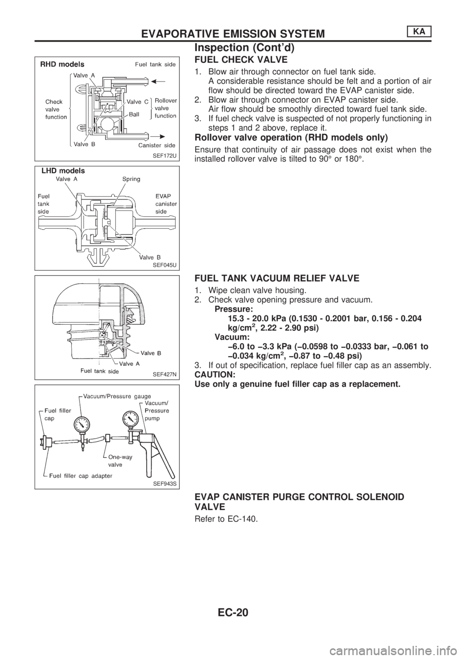
FUEL CHECK VALVE
1. Blow air through connector on fuel tank side.
A considerable resistance should be felt and a portion of air
flow should be directed toward the EVAP canister side.
2. Blow air through connector on EVAP canister side.
Air flow should be smoothly directed toward fuel tank side.
3. If fuel check valve is suspected of not properly functioning in
steps 1 and 2 above, replace it.
Rollover valve operation (RHD models only)
Ensure that continuity of air passage does not exist when the
installed rollover valve is tilted to 90É or 180É.
FUEL TANK VACUUM RELIEF VALVE
1. Wipe clean valve housing.
2. Check valve opening pressure and vacuum.
Pressure:
15.3 - 20.0 kPa (0.1530 - 0.2001 bar, 0.156 - 0.204
kg/cm
2, 2.22 - 2.90 psi)
Vacuum:
þ6.0 to þ3.3 kPa (þ0.0598 to þ0.0333 bar, þ0.061 to
þ0.034 kg/cm
2, þ0.87 to þ0.48 psi)
3. If out of specification, replace fuel filler cap as an assembly.
CAUTION:
Use only a genuine fuel filler cap as a replacement.
EVAP CANISTER PURGE CONTROL SOLENOID
VALVE
Refer to EC-140.
SEF172U
SEF045U
SEF427N
SEF943S
EVAPORATIVE EMISSION SYSTEMKA
Inspection (Cont'd)
EC-20
Page 200 of 1659
![NISSAN PICK-UP 1998 Repair Manual SELF-DIAGNOSTIC MODE
Regarding items detected in ``SELF-DIAG RESULTS mode, refer to ``DIAGNOSTIC TROUBLE CODE
INDEX, EC-1.
DATA MONITOR MODE
Monitored item
[Unit]ECM
input
signalsMain
signalsDescr NISSAN PICK-UP 1998 Repair Manual SELF-DIAGNOSTIC MODE
Regarding items detected in ``SELF-DIAG RESULTS mode, refer to ``DIAGNOSTIC TROUBLE CODE
INDEX, EC-1.
DATA MONITOR MODE
Monitored item
[Unit]ECM
input
signalsMain
signalsDescr](/manual-img/5/57374/w960_57374-199.png)
SELF-DIAGNOSTIC MODE
Regarding items detected in ``SELF-DIAG RESULTS'' mode, refer to ``DIAGNOSTIC TROUBLE CODE
INDEX'', EC-1.
DATA MONITOR MODE
Monitored item
[Unit]ECM
input
signalsMain
signalsDescription Remarks
CMPSRPM
(POS) [rpm]
jj
lIndicates the engine speed computed
from the POS signal (1É signal) of the
camshaft position sensor.
MAS AIR/FL SE [V]
jjlThe signal voltage of the mass air flow
sensor is displayed.lWhen the engine is stopped, a certain
value is indicated.
COOLAN TEMP/S
[ÉC] or [ÉF]
jj
lThe engine coolant temperature (deter-
mined by the signal voltage of the engine
coolant temperature sensor) is displayed.lWhen the engine coolant temperature
sensor is open or short-circuited, ECM
enters fail-safe mode. The engine coolant
temperature determined by the ECM is
displayed.
O2 SEN [V]
jjlThe signal voltage of the heated oxygen
sensor is displayed.lLHD models only
M/R F/C MNT
[RICH/LEAN]
jj
lDisplay of heated oxygen sensor signal
during air-fuel ratio feedback control:
RICH ... means the mixture became
``rich'', and control is being affected
toward a leaner mixture.
LEAN ... means the mixture became
``lean'', and control is being affected
toward a rich mixture.lAfter turning ON the ignition switch,
``RICH'' is displayed until air-fuel mixture
ratio feedback control begins.
lWhen the air-fuel ratio feedback is
clamped, the value just before the clamp-
ing is displayed continuously.
lLHD models only
VHCL SPEED SE
[km/h] or [mph]
jjlThe vehicle speed computed from the
vehicle speed sensor signal is displayed.
BATTERY VOLT [V]
jjlThe power supply voltage of ECM is dis-
played.
THRTL POS SEN [V]
jjlThe throttle position sensor signal volt-
age is displayed.
INT/A TEMP SE
[ÉC] or [ÉF]
j
lThe intake air temperature (determined
by the signal voltage of the intake air
temperature sensor) is indicated.
START SIGNAL
[ON/OFF]
jjlIndicates [ON/OFF] condition from the
starter signal.lAfter starting the engine, [OFF] is
displayed regardless of the starter signal.
CLSD THL/POSI
[ON/OFF]
jj
lIndicates [ON/OFF] condition from the
throttle position sensor signal.
AIR COND SIG
[ON/OFF]
jj
lIndicates [ON/OFF] condition of the air
conditioner switch as determined by the
air conditioner signal.
P/N POSI SW
[ON/OFF]
jj
lIndicates [ON/OFF] condition from the
park/neutral position switch signal.
PW/ST SIGNAL
[ON/OFF]
jj
l[ON/OFF] condition of the power steering
oil pressure switch determined by the
power steering oil pressure signal is indi-
cated.
NOTE:
Any monitored item that does not match the vehicle being diagnosed is deleted from the display automatically.
ON BOARD DIAGNOSTIC SYSTEM DESCRIPTIONKA
CONSULT (Cont'd)
EC-48
Page 207 of 1659

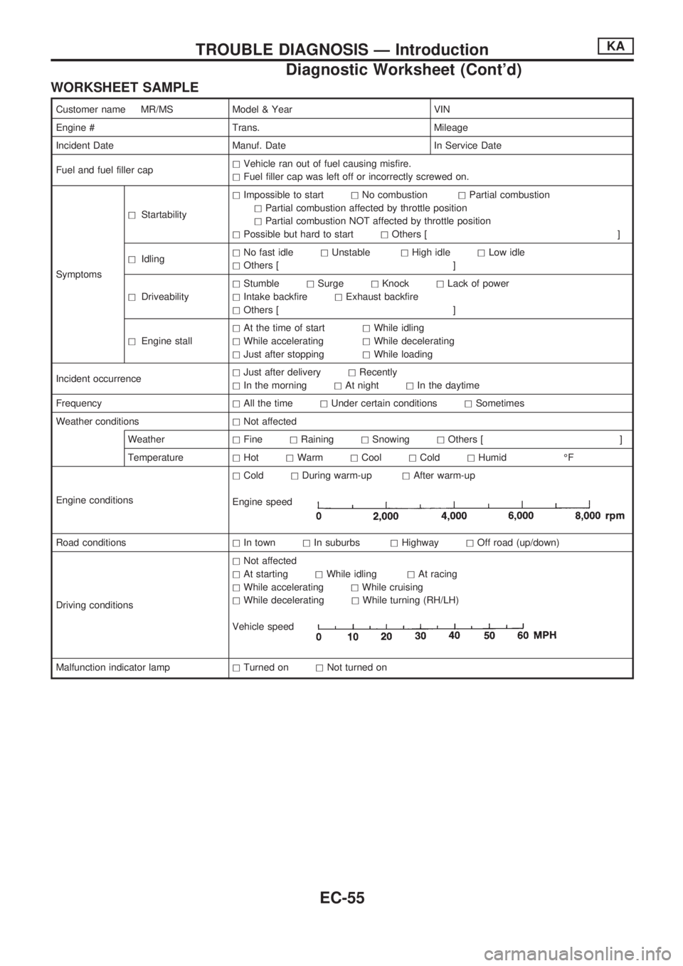
WORKSHEET SAMPLE
Customer name MR/MS Model & Year VIN
Engine # Trans. Mileage
Incident Date Manuf. Date In Service Date
Fuel and fuel filler caphVehicle ran out of fuel causing misfire.
hFuel filler cap was left off or incorrectly screwed on.
SymptomshStartabilityhImpossible to starthNo combustionhPartial combustion
hPartial combustion affected by throttle position
hPartial combustion NOT affected by throttle position
hPossible but hard to starthOthers [ ]
hIdlinghNo fast idlehUnstablehHigh idlehLow idle
hOthers [ ]
hDriveabilityhStumblehSurgehKnockhLack of power
hIntake backfirehExhaust backfire
hOthers [ ]
hEngine stallhAt the time of starthWhile idling
hWhile acceleratinghWhile decelerating
hJust after stoppinghWhile loading
Incident occurrencehJust after deliveryhRecently
hIn the morninghAt nighthIn the daytime
FrequencyhAll the timehUnder certain conditionshSometimes
Weather conditionshNot affected
WeatherhFinehRaininghSnowinghOthers [ ]
TemperaturehHothWarmhCoolhColdhHumid ÉF
Engine conditionshColdhDuring warm-uphAfter warm-up
Engine speed
Road conditionshIn townhIn suburbshHighwayhOff road (up/down)
Driving conditionshNot affected
hAt startinghWhile idlinghAt racing
hWhile acceleratinghWhile cruising
hWhile deceleratinghWhile turning (RH/LH)
Vehicle speed
Malfunction indicator lamphTurned onhNot turned on
TROUBLE DIAGNOSIS Ð IntroductionKA
Diagnostic Worksheet (Cont'd)
EC-55
Page 340 of 1659
4. Clean fuel sump of nozzle body using Tool.
5. Clean nozzle seat by using Tool.
This job should be performed with extra precautions, since
efficiency of nozzle depends greatly on a good nozzle seat.
6. Clean spray hole of nozzle body by using Tool.
To prevent spray hole from canting, always clean it by start-
ing with inner side and working towards outside.
7. Decarbon nozzle needle tip by using Tool.
8. Check needle for proper position.
(1) Pull needle about halfway out from body and then release it.
(2) Needle should sink into body very smoothly from just its own
weight.
(3) Repeat this test and rotate needle slightly each time.
If needle fails to sink smoothly from any position, replace
both needle and body as a unit.
SEF831-B
SEF832-B
SEF833
SEF834
SEF835
INJECTION NOZZLETD
Cleaning (Cont'd)
EC-188
Page 539 of 1659
Installation
1. Lower antenna rod by operating antenna motor.
2. Insert gear section of antenna rope into place with it facing
toward antenna motor.
3. As soon as antenna rope is wound on antenna motor, stop
antenna motor. Insert antenna rod lower end into antenna
motor pipe.
4. Retract antenna rod completely by operating antenna motor.
5. Install antenna nut and base.
ANTENNA ASSEMBLY REPLACEMENT
1. Remove antenna nut and antenna base.
2. Loosen bolts at antenna bracket and disconnect power
antenna connector.
3. Disconnect antenna feeder cable jack shown in ``LOCATION
OF ANTENNA''.
4. Remove fender protector.
5. Remove the grommet and pull the feeder cable out from
fender inner.
6. Remove antenna assembly and replace with a new one.
SEL342V
SEL240V
SEL340V
AUDIO ANTENNA
Power Antenna (Cont'd)
EL-149
Page 678 of 1659
Assembly
1. Install valve component parts.
lAlways use new valve oil seal. Refer to OIL SEAL
REPLACEMENT.
lBefore installing valve oil seal, install inner valve spring
seat.
lInstall outer valve spring (uneven pitch type) with its
narrow pitch side toward cylinder head side.
lAfter installing valve component parts, use plastic ham-
mer to lightly tap valve stem tip to assure a proper fit.
2. Install camshaft, placing knock pin towards front of engine
and in the top position.
lApply engine oil to camshaft when mounting onto cylin-
der head.
3. Install camshaft brackets.
lFront mark is punched on the camshaft bracket.
Location (from front side)Identification
Mark Punched
No. 1 51 Ð
No. 2 52 2
No. 3 53 Ð
No. 4 52 4
No. 5 55 Ð
4. Install rocker shaft with rocker arms.
lInstall retainer with cutout facing direction shown in figure at
left.
SEM638B
SEM236C
SEM606F
SEM399E
SEM274C
CYLINDER HEADKA
EM-33
Page 692 of 1659

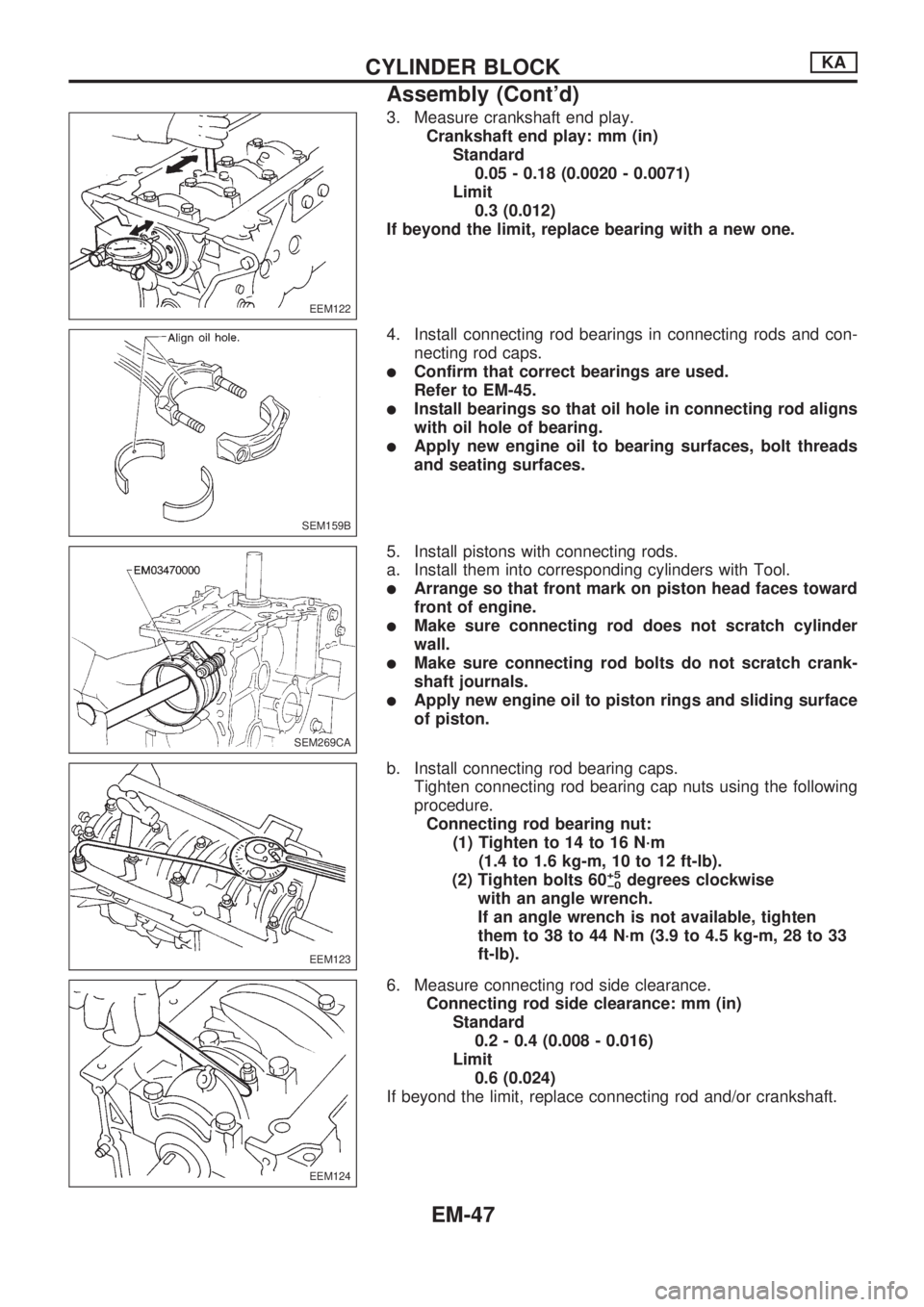
3. Measure crankshaft end play.
Crankshaft end play: mm (in)
Standard
0.05 - 0.18 (0.0020 - 0.0071)
Limit
0.3 (0.012)
If beyond the limit, replace bearing with a new one.
4. Install connecting rod bearings in connecting rods and con-
necting rod caps.
lConfirm that correct bearings are used.
Refer to EM-45.
lInstall bearings so that oil hole in connecting rod aligns
with oil hole of bearing.
lApply new engine oil to bearing surfaces, bolt threads
and seating surfaces.
5. Install pistons with connecting rods.
a. Install them into corresponding cylinders with Tool.
lArrange so that front mark on piston head faces toward
front of engine.
lMake sure connecting rod does not scratch cylinder
wall.
lMake sure connecting rod bolts do not scratch crank-
shaft journals.
lApply new engine oil to piston rings and sliding surface
of piston.
b. Install connecting rod bearing caps.
Tighten connecting rod bearing cap nuts using the following
procedure.
Connecting rod bearing nut:
(1) Tighten to 14 to 16 N´m
(1.4 to 1.6 kg-m, 10 to 12 ft-lb).
(2) Tighten bolts 60
+5
þ0degrees clockwise
with an angle wrench.
If an angle wrench is not available, tighten
them to 38 to 44 N´m (3.9 to 4.5 kg-m, 28 to 33
ft-lb).
6. Measure connecting rod side clearance.
Connecting rod side clearance: mm (in)
Standard
0.2 - 0.4 (0.008 - 0.016)
Limit
0.6 (0.024)
If beyond the limit, replace connecting rod and/or crankshaft.
EEM122
SEM159B
SEM269CA
EEM123
EEM124
CYLINDER BLOCKKA
Assembly (Cont'd)
EM-47
Page 707 of 1659
Assembly
1. Assemble rocker shaft component parts.
lFace punch mark toward the front of the engine.
Identification of rocker arms
Identification mark
(At area
Vaon rocker arm)For use with
Two ridges Intake
No ridge Exhaust
2. Install valve component parts.
Identification of valves
Identification mark
(on intake and exhaust valve)
Engine
Intake valve Exhaust valve
2 B TD25
lAlways use new valve oil seal. (Refer to EM-68.)
lInstall valve spring (uneven pitch type) with its narrow
pitch side toward cylinder head side.
DEM034
SEM066C
MEM180A
SEM615F
SEM638B
CYLINDER HEADTD
EM-62