1998 NISSAN PICK-UP wheel bolt torque
[x] Cancel search: wheel bolt torquePage 697 of 1659
Removal
Removal order and pointsApplied model
2WD 4WD
1 Remove undercover.jj
2 Drain engine oil.jj
3Remove front propeller shaft
from front differential carrier.Ðj
4Remove front drive shaft fix-
ing bolts (RH & LH).Ðj
5Remove front suspension
crossmember.jj
6Remove differential front
mounting bolts (RH & LH)
and rear mounting bolts.Ðj
7Remove front differential car-
rier.ÐjRemoval order and pointsApplied model
2WD 4WD
8Remove front differential car-
rier mounting bracket.Ðj
9Remove transmission to rear
engine mounting bracket
nuts (RH & LH).jj
10Remove engine mounting
bolts or nuts (RH & LH).jj
11Lift up engine.
If necessary, disconnect
exhaust tube.jj
12 Remove oil pan.jj
WARNING:
lPlace vehicle on a flat and solid surface.
lPlace chocks at front and rear of rear wheels.
lYou should not remove oil pan until exhaust system and
cooling system have completely cooled off.
Otherwise, you may burn yourself and/or fire may break
out in the fuel line.
lWhen removing front and/or rear engine mounting bolts
or nuts, lift up slightly engine for safety work.
CAUTION:
lIn lifting engine, be careful not to hit against adjacent
parts, especially against accelerator wire casing end,
brake tube and brake master cylinder.
lFor tightening torque, refer to EM-71, MT and PD sec-
tions.
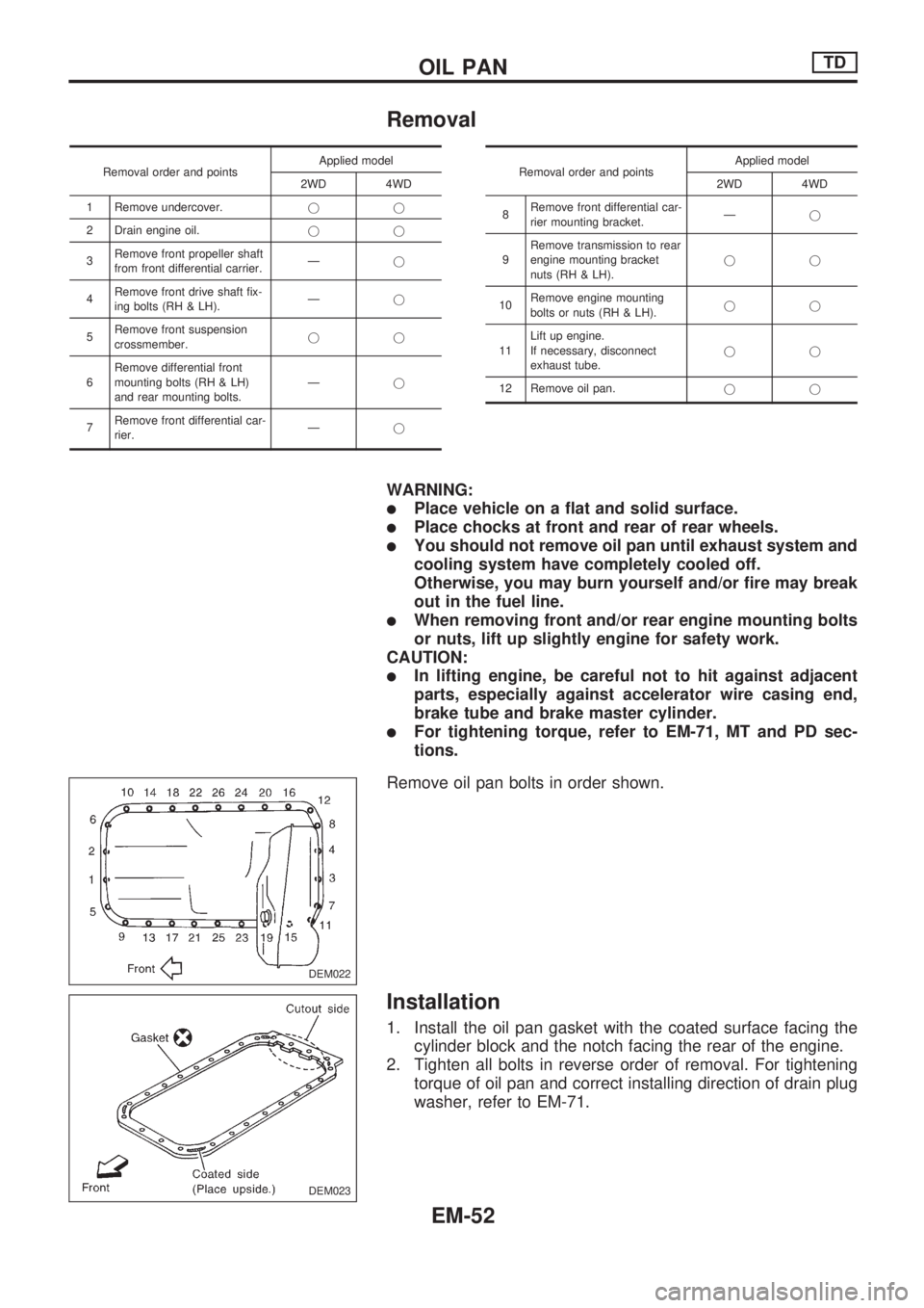
Remove oil pan bolts in order shown.
Installation
1. Install the oil pan gasket with the coated surface facing the
cylinder block and the notch facing the rear of the engine.
2. Tighten all bolts in reverse order of removal. For tightening
torque of oil pan and correct installing direction of drain plug
washer, refer to EM-71.
DEM022
DEM023
OIL PANTD
EM-52
Page 770 of 1659
Front Axle and Front Suspension Parts
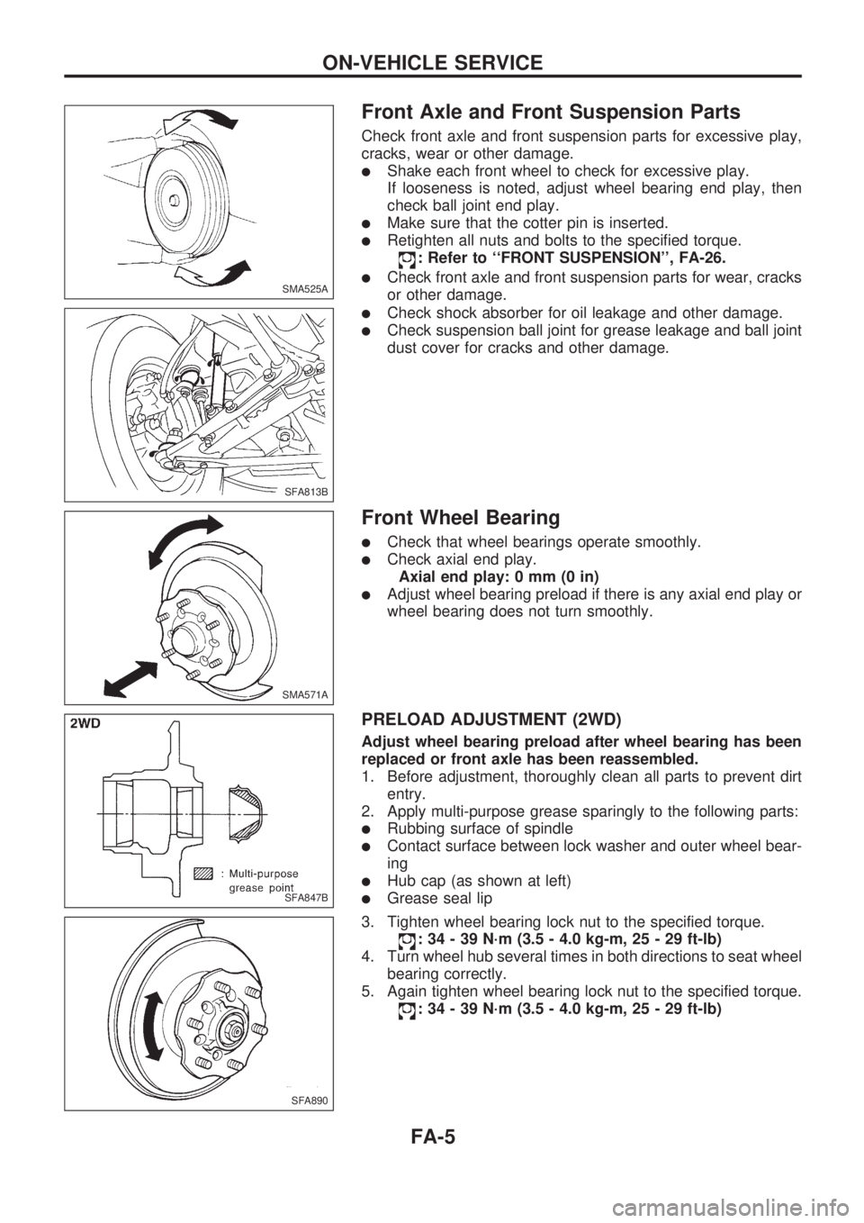
Check front axle and front suspension parts for excessive play,
cracks, wear or other damage.
lShake each front wheel to check for excessive play.
If looseness is noted, adjust wheel bearing end play, then
check ball joint end play.
lMake sure that the cotter pin is inserted.
lRetighten all nuts and bolts to the specified torque.
: Refer to ``FRONT SUSPENSION'', FA-26.
lCheck front axle and front suspension parts for wear, cracks
or other damage.
lCheck shock absorber for oil leakage and other damage.
lCheck suspension ball joint for grease leakage and ball joint
dust cover for cracks and other damage.
Front Wheel Bearing
lCheck that wheel bearings operate smoothly.
lCheck axial end play.
Axial end play: 0 mm (0 in)
lAdjust wheel bearing preload if there is any axial end play or
wheel bearing does not turn smoothly.
PRELOAD ADJUSTMENT (2WD)
Adjust wheel bearing preload after wheel bearing has been
replaced or front axle has been reassembled.
1. Before adjustment, thoroughly clean all parts to prevent dirt
entry.
2. Apply multi-purpose grease sparingly to the following parts:
lRubbing surface of spindle
lContact surface between lock washer and outer wheel bear-
ing
lHub cap (as shown at left)
lGrease seal lip
3. Tighten wheel bearing lock nut to the specified torque.
: 34 - 39 N´m (3.5 - 4.0 kg-m, 25 - 29 ft-lb)
4. Turn wheel hub several times in both directions to seat wheel
bearing correctly.
5. Again tighten wheel bearing lock nut to the specified torque.
: 34 - 39 N´m (3.5 - 4.0 kg-m, 25 - 29 ft-lb)
SMA525A
SFA813B
SMA571A
SFA847B
SFA890
ON-VEHICLE SERVICE
FA-5
Page 771 of 1659
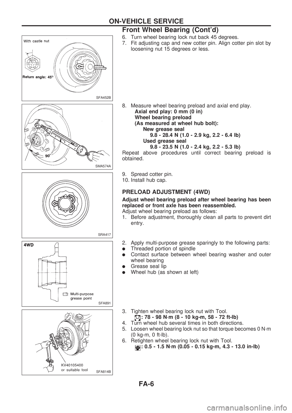
6. Turn wheel bearing lock nut back 45 degrees.
7. Fit adjusting cap and new cotter pin. Align cotter pin slot by
loosening nut 15 degrees or less.
8. Measure wheel bearing preload and axial end play.
Axial end play: 0 mm (0 in)
Wheel bearing preload
(As measured at wheel hub bolt):
New grease seal
9.8 - 28.4 N (1.0 - 2.9 kg, 2.2 - 6.4 lb)
Used grease seal
9.8 - 23.5 N (1.0 - 2.4 kg, 2.2 - 5.3 lb)
Repeat above procedures until correct bearing preload is
obtained.
9. Spread cotter pin.
10. Install hub cap.
PRELOAD ADJUSTMENT (4WD)
Adjust wheel bearing preload after wheel bearing has been
replaced or front axle has been reassembled.
Adjust wheel bearing preload as follows:
1. Before adjustment, thoroughly clean all parts to prevent dirt
entry.
2. Apply multi-purpose grease sparingly to the following parts:
lThreaded portion of spindle
lContact surface between wheel bearing washer and outer
wheel bearing
lGrease seal lip
lWheel hub (as shown at left)
3. Tighten wheel bearing lock nut with Tool.
: 78 - 98 N´m (8 - 10 kg-m, 58 - 72 ft-lb)
4. Turn wheel hub several times in both directions.
5. Loosen wheel bearing lock nut so that torque becomes 0 N´m
(0 kg-m, 0 ft-lb).
6. Retighten wheel bearing lock nut with Tool.
: 0.5 - 1.5 N´m (0.05 - 0.15 kg-m, 4.3 - 13.0 in-lb)
SFA452B
SMA574A
SRA417
SFA891
SFA814B
ON-VEHICLE SERVICE
Front Wheel Bearing (Cont'd)
FA-6
Page 775 of 1659
TOE-IN
Measure toe-in using the following procedure.
WARNING:
lAlways perform the following procedure on a flat sur-
face.
lMake sure that no one is in front of the vehicle before
pushing it.
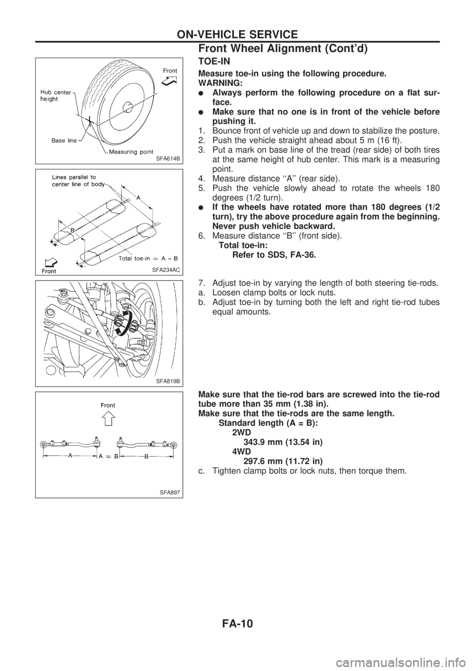
1. Bounce front of vehicle up and down to stabilize the posture.
2. Push the vehicle straight ahead about 5 m (16 ft).
3. Put a mark on base line of the tread (rear side) of both tires
at the same height of hub center. This mark is a measuring
point.
4. Measure distance ``A'' (rear side).
5. Push the vehicle slowly ahead to rotate the wheels 180
degrees (1/2 turn).
lIf the wheels have rotated more than 180 degrees (1/2
turn), try the above procedure again from the beginning.
Never push vehicle backward.
6. Measure distance ``B'' (front side).
Total toe-in:
Refer to SDS, FA-36.
7. Adjust toe-in by varying the length of both steering tie-rods.
a. Loosen clamp bolts or lock nuts.
b. Adjust toe-in by turning both the left and right tie-rod tubes
equal amounts.
Make sure that the tie-rod bars are screwed into the tie-rod
tube more than 35 mm (1.38 in).
Make sure that the tie-rods are the same length.
Standard length (A = B):
2WD
343.9 mm (13.54 in)
4WD
297.6 mm (11.72 in)
c. Tighten clamp bolts or lock nuts, then torque them.
SFA614B
SFA234AC
SFA819B
SFA897
ON-VEHICLE SERVICE
Front Wheel Alignment (Cont'd)
FA-10
Page 800 of 1659
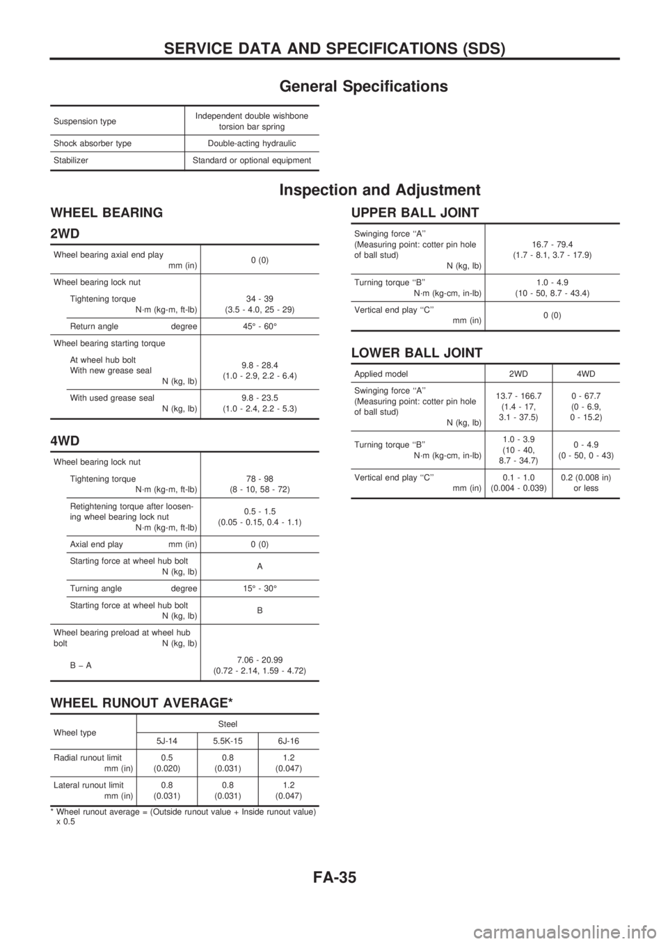
General Specifications
Suspension typeIndependent double wishbone
torsion bar spring
Shock absorber type Double-acting hydraulic
Stabilizer Standard or optional equipment
Inspection and Adjustment
WHEEL BEARING
2WD
Wheel bearing axial end play
mm (in)0 (0)
Wheel bearing lock nut
Tightening torque
N´m (kg-m, ft-lb)34-39
(3.5 - 4.0, 25 - 29)
Return angle degree 45É - 60É
Wheel bearing starting torque
At wheel hub bolt
With new grease seal
N (kg, lb)9.8 - 28.4
(1.0 - 2.9, 2.2 - 6.4)
With used grease seal
N (kg, lb)9.8 - 23.5
(1.0 - 2.4, 2.2 - 5.3)
4WD
Wheel bearing lock nut
Tightening torque
N´m (kg-m, ft-lb)78-98
(8 - 10, 58 - 72)
Retightening torque after loosen-
ing wheel bearing lock nut
N´m (kg-m, ft-lb)0.5 - 1.5
(0.05 - 0.15, 0.4 - 1.1)
Axial end play mm (in) 0 (0)
Starting force at wheel hub bolt
N (kg, lb)A
Turning angle degree 15É - 30É
Starting force at wheel hub bolt
N (kg, lb)B
Wheel bearing preload at wheel hub
bolt N (kg, lb)
BþA7.06 - 20.99
(0.72 - 2.14, 1.59 - 4.72)
WHEEL RUNOUT AVERAGE*
Wheel typeSteel
5J-14 5.5K-15 6J-16
Radial runout limit
mm (in)0.5
(0.020)0.8
(0.031)1.2
(0.047)
Lateral runout limit
mm (in)0.8
(0.031)0.8
(0.031)1.2
(0.047)
* Wheel runout average = (Outside runout value + Inside runout value)
x 0.5
UPPER BALL JOINT
Swinging force ``A''
(Measuring point: cotter pin hole
of ball stud)
N (kg, lb)16.7 - 79.4
(1.7 - 8.1, 3.7 - 17.9)
Turning torque ``B''
N´m (kg-cm, in-lb)1.0 - 4.9
(10 - 50, 8.7 - 43.4)
Vertical end play ``C''
mm (in)0 (0)
LOWER BALL JOINT
Applied model 2WD 4WD
Swinging force ``A''
(Measuring point: cotter pin hole
of ball stud)
N (kg, lb)13.7 - 166.7
(1.4 - 17,
3.1 - 37.5)0 - 67.7
(0 - 6.9,
0 - 15.2)
Turning torque ``B''
N´m (kg-cm, in-lb)1.0 - 3.9
(10 - 40,
8.7 - 34.7)0 - 4.9
(0 - 50, 0 - 43)
Vertical end play ``C''
mm (in)0.1 - 1.0
(0.004 - 0.039)0.2 (0.008 in)
or less
SERVICE DATA AND SPECIFICATIONS (SDS)
FA-35
Page 804 of 1659

GENERAL INFORMATION
SECTION
GI
CONTENTS
PRECAUTIONS......................................................... 1
Precautions for Supplemental Restraint
System (SRS) ``AIR BAG'' (4WD models)............. 1
Precautions for Supplemental Restraint
System (SRS) ``AIR BAG'' (2WD models)............. 1
Precautions for NATS ............................................ 2
General Precautions .............................................. 2
Precautions for Multiport Fuel Injection System
or ECCS Engine .................................................... 4
Precautions for Three Way Catalyst
(If so equipped) ...................................................... 4
Precautions for Engine Oils ................................... 4
Precautions for Fuel............................................... 5
Precautions for Air Conditioning ............................ 6
HOW TO USE THIS MANUAL.................................. 7
HOW TO READ WIRING DIAGRAMS...................... 9
Sample/Wiring Diagram - EXAMPL - .................... 9
Description ........................................................... 11
HOW TO CHECK TERMINAL................................. 18
How to Probe Connectors ................................... 18
How to Check Enlarged Contact Spring of
Terminal ............................................................... 19
Waterproof Connector Inspection ........................ 20
Terminal Lock Inspection ..................................... 20
HOW TO PERFORM EFFICIENT DIAGNOSIS
FOR AN ELECTRICAL INCIDENT......................... 21
Work Flow ............................................................ 21HOW TO PERFORM EFFICIENT DIAGNOSIS...... 22
Incident Simulation Tests..................................... 22
Circuit Inspection ................................................. 25
HOW TO FOLLOW FLOW CHART IN
TROUBLE DIAGNOSES......................................... 31
How to Follow This Flow Chart ........................... 32
CONSULT CHECKING SYSTEM............................ 34
Function and System Application ........................ 34
Lithium Battery Replacement............................... 34
Checking Equipment ............................................ 35
Loading Procedure............................................... 36
CONSULT Data Link Connector (DLC) Circuit ... 36
IDENTIFICATION INFORMATION.......................... 37
Model Variation .................................................... 37
Identification Number ........................................... 40
Dimensions .......................................................... 44
Wheels and Tires ................................................. 46
LIFTING POINTS AND TOW TRUCK TOWING..... 47
Pantograph Jack .................................................. 47
Screw Jack........................................................... 48
Garage Jack and Safety Stand ........................... 49
2-pole Lift ............................................................. 50
Tow Truck Towing ............................................... 51
Towing Point ........................................................ 53
TIGHTENING TORQUE OF STANDARD BOLTS.. 54
SAE J1930 TERMINOLOGY LIST.......................... 55
SAE J1930 Terminology List ............................... 55
GI
Page 870 of 1659
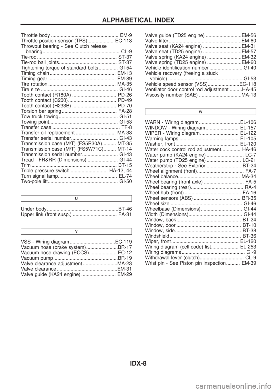
Throttle body ................................................. EM-9
Throttle position sensor (TPS)................... EC-113
Throwout bearing - See Clutch release
bearing........................................................ CL-9
Tie-rod .......................................................... ST-37
Tie-rod ball joints.......................................... ST-37
Tightening torque of standard bolts .............. GI-54
Timing chain ................................................ EM-13
Timing gear ................................................. EM-89
Tire rotation ................................................. MA-35
Tire size ........................................................ GI-46
Tooth contact (R180A) ................................ PD-26
Tooth contact (C200) ................................... PD-49
Tooth contact (H233B) ................................ PD-70
Torsion bar spring ........................................ FA-28
Tow truck towing ........................................... GI-51
Towing point.................................................. GI-53
Transfer case ................................................. TF-8
Transfer oil replacement ............................. MA-33
Transfer serial number.................................. GI-43
Transmission case (M/T) (FS5R30A).......... MT-35
Transmission case (M/T) (FS5W71C)......... MT-14
Transmission serial number.......................... GI-43
Tread - FR&RR (Dimensions) ...................... GI-44
Trim .............................................................. BT-15
Triple pressure switch ........................... HA-12, 44
Turn signal lamp........................................... EL-74
Two-pole lift................................................... GI-50
U
Under body ....................................................BT-46
Upper link (front susp.) ................................ FA-31
V
VSS - Wiring diagram .................................EC-119
Vacuum hose (brake system) .......................BR-17
Vacuum hose drawing (ECCS).....................EC-12
Vacuum pump ...............................................BR-19
Valve clearance adjustment .........................MA-23
Valve clearance ............................................EM-31
Valve guide (KA24 engine) ......................... EM-29Valve guide (TD25 engine) ..........................EM-56
Valve lifter .....................................................EM-60
Valve seat (KA24 engine) ............................EM-31
Valve seat (TD25 engine) ............................EM-57
Valve spring (KA24 engine) .........................EM-32
Valve spring (TD25 engine) .........................EM-60
Vehicle identification number .........................GI-40
Vehicle recovery (freeing a stuck
vehicle) .......................................................GI-53
Vehicle speed sensor (VSS).......................EC-118
Ventilator door control rod adjustment .........HA-45
Viscosity number (SAE) ...............................MA-13
W
WARN - Wiring diagram ..............................EL-106
WINDOW - Wiring diagram ........................ EL-157
WIPER - Wiring diagram ............................ EL-122
Warning lamps ........................................... EL-105
Washer, front .............................................. EL-120
Water cock control rod adjustment.............. HA-46
Water pump (KA24 engine) ........................... LC-7
Water pump (TD25 engine) ......................... LC-21
Weatherstrip - See Exterior ......................... BT-24
Wheel alignment (front).................................. FA-7
Wheel balance............................................. MA-34
Wheel bearing (front axle) ............................. FA-5
Wheel bearing (rear)...................................... RA-4
Wheel hub (front) ......................................... FA-16
Wheel sensors (ABS) .................................. BR-35
Wheel size .................................................... GI-46
Wheelbase (Dimensions) .............................. GI-44
Width (Dimensions)....................................... GI-44
Window, back ............................................... BT-24
Window, door ............................................... BT-10
Window, side ................................................ BT-38
Windshield .................................................... BT-36
Wiper, front ................................................. EL-120
Wiring diagram (cell code) list.................... EL-253
Wiring diagrams .............................................. GI-9
Withdrawal lever (clutch)................................ CL-9
Wrist pin - See Piston pin inspection .......... EM-39
ALPHABETICAL INDEX
IDX-8
Page 1120 of 1659
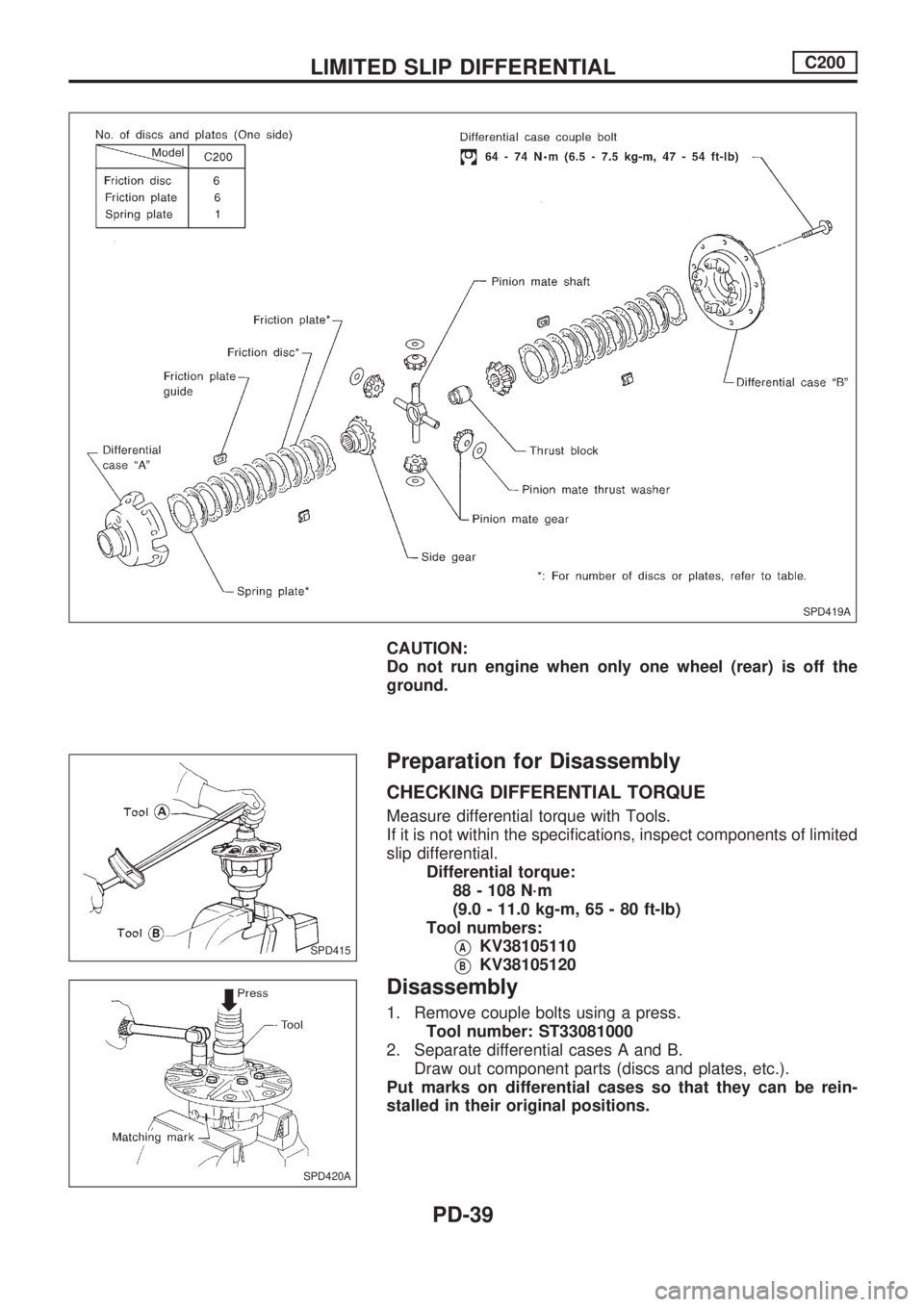
CAUTION:
Do not run engine when only one wheel (rear) is off the
ground.
Preparation for Disassembly
CHECKING DIFFERENTIAL TORQUE
Measure differential torque with Tools.
If it is not within the specifications, inspect components of limited
slip differential.
Differential torque:
88 - 108 N´m
(9.0 - 11.0 kg-m, 65 - 80 ft-lb)
Tool numbers:
VAKV38105110
VBKV38105120
Disassembly
1. Remove couple bolts using a press.
Tool number: ST33081000
2. Separate differential cases A and B.
Draw out component parts (discs and plates, etc.).
Put marks on differential cases so that they can be rein-
stalled in their original positions.
SPD419A
SPD415
SPD420A
LIMITED SLIP DIFFERENTIALC200
PD-39