1998 NISSAN PICK-UP fuse box
[x] Cancel search: fuse boxPage 197 of 1659
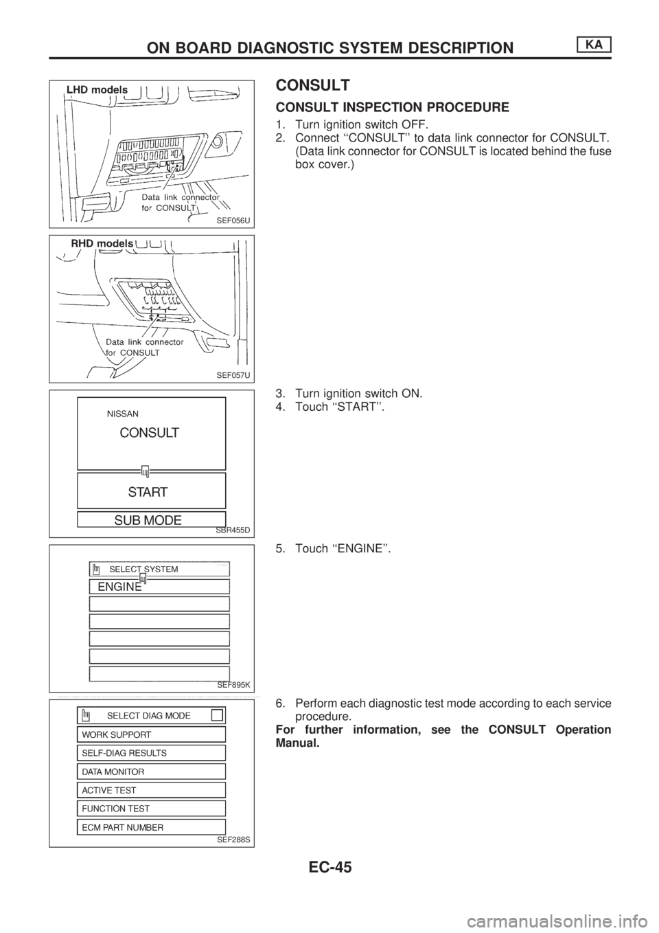
CONSULT
CONSULT INSPECTION PROCEDURE
1. Turn ignition switch OFF.
2. Connect ``CONSULT'' to data link connector for CONSULT.
(Data link connector for CONSULT is located behind the fuse
box cover.)
3. Turn ignition switch ON.
4. Touch ``START''.
5. Touch ``ENGINE''.
6. Perform each diagnostic test mode according to each service
procedure.
For further information, see the CONSULT Operation
Manual.
SEF056U
SEF057U
SBR455D
SEF895K
SEF288S
ON BOARD DIAGNOSTIC SYSTEM DESCRIPTIONKA
EC-45
Page 438 of 1659
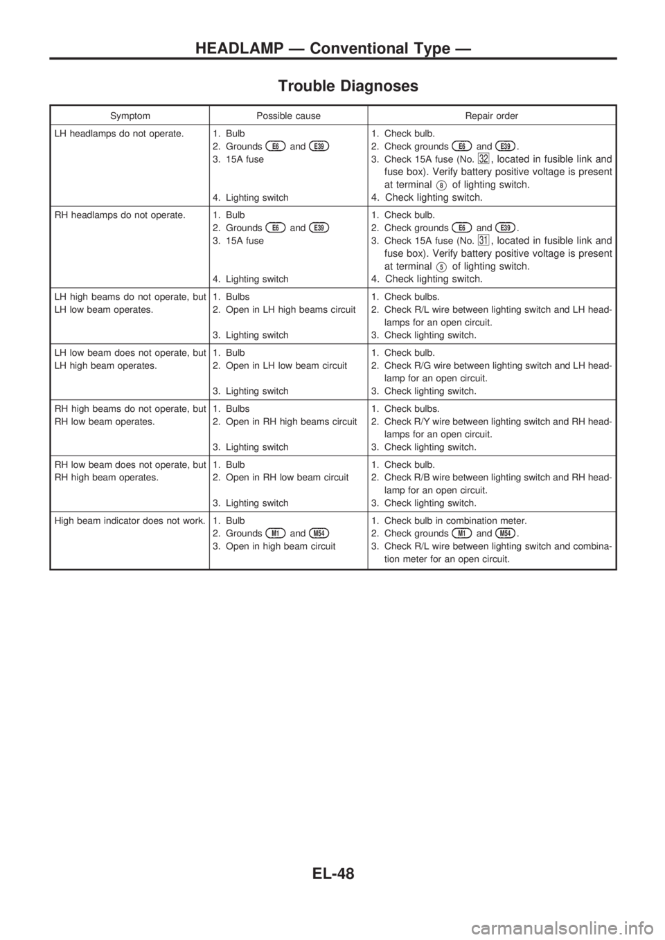
Trouble Diagnoses
Symptom Possible cause Repair order
LH headlamps do not operate. 1. Bulb
2. Grounds
E6andE39
3. 15A fuse
4. Lighting switch1. Check bulb.
2. Check grounds
E6andE39.
3. Check 15A fuse (No.
32, located in fusible link and
fuse box). Verify battery positive voltage is present
at terminal
V8of lighting switch.
4. Check lighting switch.
RH headlamps do not operate. 1. Bulb
2. Grounds
E6andE39
3. 15A fuse
4. Lighting switch1. Check bulb.
2. Check grounds
E6andE39.
3. Check 15A fuse (No.
31, located in fusible link and
fuse box). Verify battery positive voltage is present
at terminal
V5of lighting switch.
4. Check lighting switch.
LH high beams do not operate, but
LH low beam operates.1. Bulbs
2. Open in LH high beams circuit
3. Lighting switch1. Check bulbs.
2. Check R/L wire between lighting switch and LH head-
lamps for an open circuit.
3. Check lighting switch.
LH low beam does not operate, but
LH high beam operates.1. Bulb
2. Open in LH low beam circuit
3. Lighting switch1. Check bulb.
2. Check R/G wire between lighting switch and LH head-
lamp for an open circuit.
3. Check lighting switch.
RH high beams do not operate, but
RH low beam operates.1. Bulbs
2. Open in RH high beams circuit
3. Lighting switch1. Check bulbs.
2. Check R/Y wire between lighting switch and RH head-
lamps for an open circuit.
3. Check lighting switch.
RH low beam does not operate, but
RH high beam operates.1. Bulb
2. Open in RH low beam circuit
3. Lighting switch1. Check bulb.
2. Check R/B wire between lighting switch and RH head-
lamp for an open circuit.
3. Check lighting switch.
High beam indicator does not work. 1. Bulb
2. Grounds
M1andM54
3. Open in high beam circuit1. Check bulb in combination meter.
2. Check grounds
M1andM54.
3. Check R/L wire between lighting switch and combina-
tion meter for an open circuit.
HEADLAMP Ð Conventional Type Ð
EL-48
Page 544 of 1659
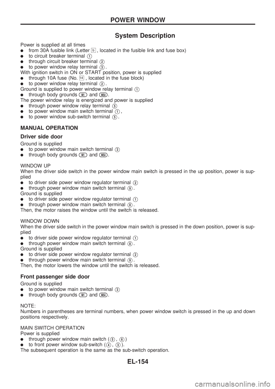
System Description
Power is supplied at all times
lfrom 30A fusible link (Letterb, located in the fusible link and fuse box)
lto circuit breaker terminalV1
lthrough circuit breaker terminalV2
lto power window relay terminalV3.
With ignition switch in ON or START position, power is supplied
lthrough 10A fuse (No.14, located in the fuse block)
lto power window relay terminalV2.
Ground is supplied to power window relay terminal
V1
lthrough body groundsM1andM54.
The power window relay is energized and power is supplied
lthrough power window relay terminalV5
lto power window main switch terminalV1,
lto power window sub-switch terminalV5.
MANUAL OPERATION
Driver side door
Ground is supplied
lto power window main switch terminalV3
lthrough body groundsM1andM54.
WINDOW UP
When the driver side switch in the power window main switch is pressed in the up position, power is sup-
plied
lto driver side power window regulator terminalV2
lthrough power window main switch terminalV9.
Ground is supplied
lto driver side power window regulator terminalV1
lthrough power window main switch terminalV8.
Then, the motor raises the window until the switch is released.
WINDOW DOWN
When the driver side switch in the power window main switch is pressed in the down position, power is sup-
plied
lto driver side power window regulator terminalV1
lthrough power window main switch terminalV8.
Ground is supplied
lto driver side power window regulator terminalV2
lthrough power window main switch terminalV9.
Then, the motor lowers the window until the switch is released.
Front passenger side door
Ground is supplied
lto power window main switch terminalV3
lthrough body groundsM1andM54.
NOTE:
Numbers in parentheses are terminal numbers, when power window switch is pressed in the up and down
positions respectively.
MAIN SWITCH OPERATION
Power is supplied
lthrough power window main switch (V5,V6)
lto front power window sub-switch (V4,V3).
The subsequent operation is the same as the sub-switch operation.
POWER WINDOW
EL-154
Page 555 of 1659
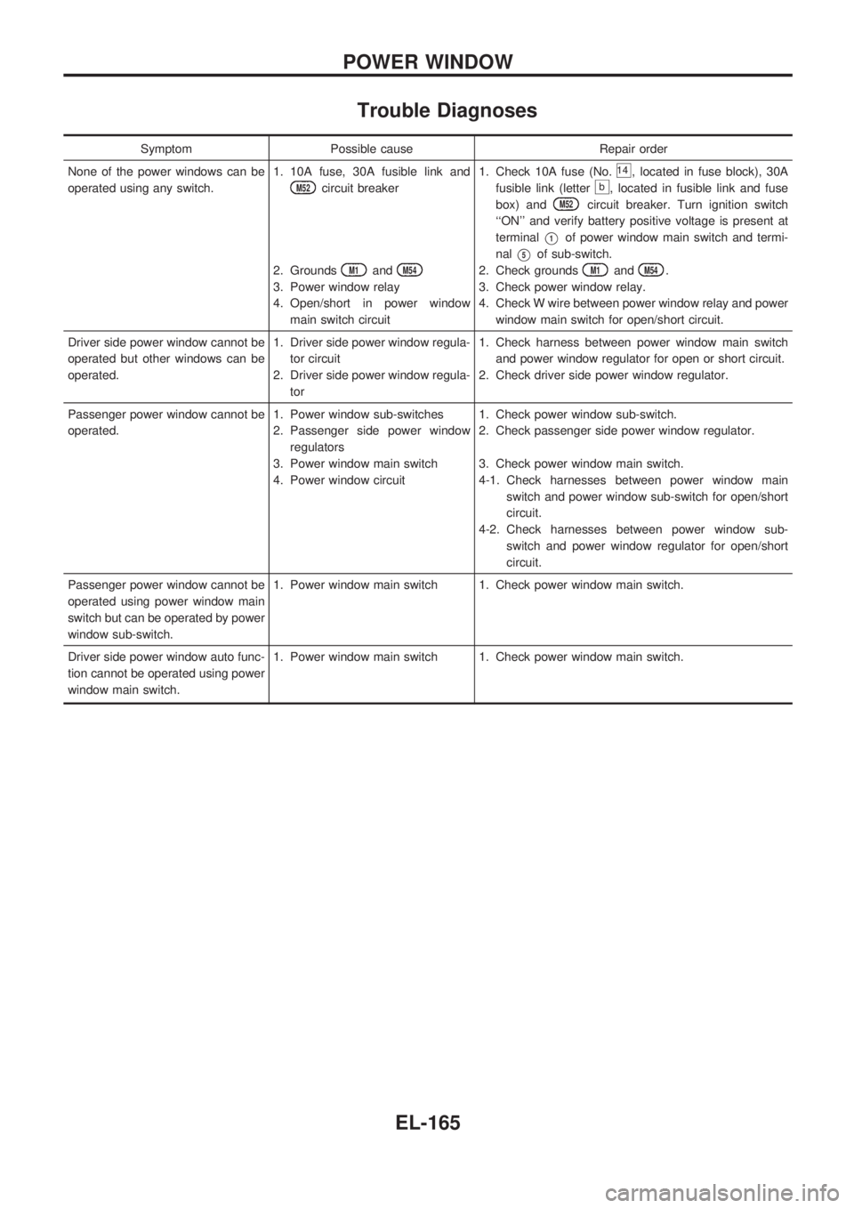
Trouble Diagnoses
Symptom Possible cause Repair order
None of the power windows can be
operated using any switch.1. 10A fuse, 30A fusible link and
M52circuit breaker
2. Grounds
M1andM54
3. Power window relay
4. Open/short in power window
main switch circuit1. Check 10A fuse (No.
14, located in fuse block), 30A
fusible link (letter
b, located in fusible link and fuse
box) and
M52circuit breaker. Turn ignition switch
``ON'' and verify battery positive voltage is present at
terminal
V1of power window main switch and termi-
nal
V5of sub-switch.
2. Check grounds
M1andM54.
3. Check power window relay.
4. Check W wire between power window relay and power
window main switch for open/short circuit.
Driver side power window cannot be
operated but other windows can be
operated.1. Driver side power window regula-
tor circuit
2. Driver side power window regula-
tor1. Check harness between power window main switch
and power window regulator for open or short circuit.
2. Check driver side power window regulator.
Passenger power window cannot be
operated.1. Power window sub-switches
2. Passenger side power window
regulators
3. Power window main switch
4. Power window circuit1. Check power window sub-switch.
2. Check passenger side power window regulator.
3. Check power window main switch.
4-1. Check harnesses between power window main
switch and power window sub-switch for open/short
circuit.
4-2. Check harnesses between power window sub-
switch and power window regulator for open/short
circuit.
Passenger power window cannot be
operated using power window main
switch but can be operated by power
window sub-switch.1. Power window main switch 1. Check power window main switch.
Driver side power window auto func-
tion cannot be operated using power
window main switch.1. Power window main switch 1. Check power window main switch.
POWER WINDOW
EL-165
Page 556 of 1659
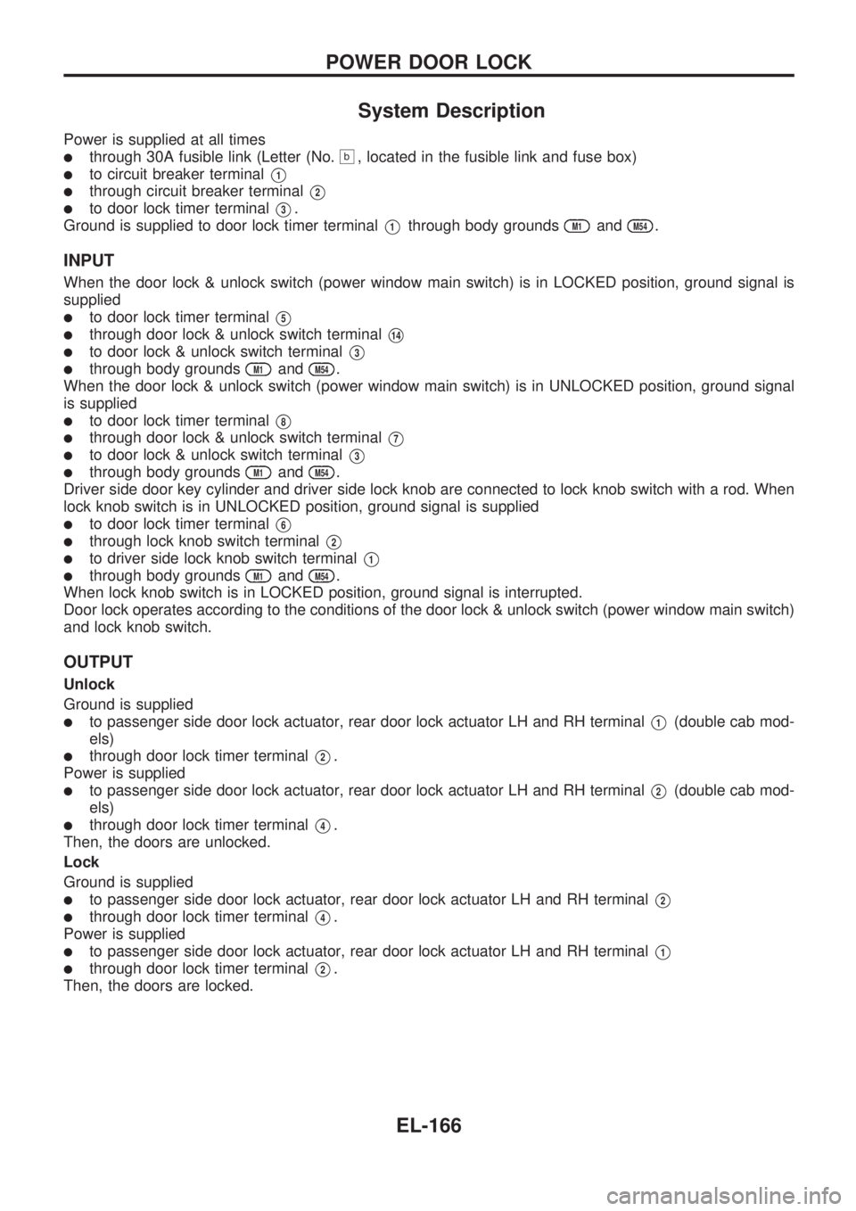
System Description
Power is supplied at all times
lthrough 30A fusible link (Letter (No.b, located in the fusible link and fuse box)
lto circuit breaker terminalV1
lthrough circuit breaker terminalV2
lto door lock timer terminalV3.
Ground is supplied to door lock timer terminal
V1through body groundsM1andM54.
INPUT
When the door lock & unlock switch (power window main switch) is in LOCKED position, ground signal is
supplied
lto door lock timer terminalV5
lthrough door lock & unlock switch terminalV14
lto door lock & unlock switch terminalV3
lthrough body groundsM1andM54.
When the door lock & unlock switch (power window main switch) is in UNLOCKED position, ground signal
is supplied
lto door lock timer terminalV8
lthrough door lock & unlock switch terminalV7
lto door lock & unlock switch terminalV3
lthrough body groundsM1andM54.
Driver side door key cylinder and driver side lock knob are connected to lock knob switch with a rod. When
lock knob switch is in UNLOCKED position, ground signal is supplied
lto door lock timer terminalV6
lthrough lock knob switch terminalV2
lto driver side lock knob switch terminalV1
lthrough body groundsM1andM54.
When lock knob switch is in LOCKED position, ground signal is interrupted.
Door lock operates according to the conditions of the door lock & unlock switch (power window main switch)
and lock knob switch.
OUTPUT
Unlock
Ground is supplied
lto passenger side door lock actuator, rear door lock actuator LH and RH terminalV1(double cab mod-
els)
lthrough door lock timer terminalV2.
Power is supplied
lto passenger side door lock actuator, rear door lock actuator LH and RH terminalV2(double cab mod-
els)
lthrough door lock timer terminalV4.
Then, the doors are unlocked.
Lock
Ground is supplied
lto passenger side door lock actuator, rear door lock actuator LH and RH terminalV2
lthrough door lock timer terminalV4.
Power is supplied
lto passenger side door lock actuator, rear door lock actuator LH and RH terminalV1
lthrough door lock timer terminalV2.
Then, the doors are locked.
POWER DOOR LOCK
EL-166
Page 571 of 1659
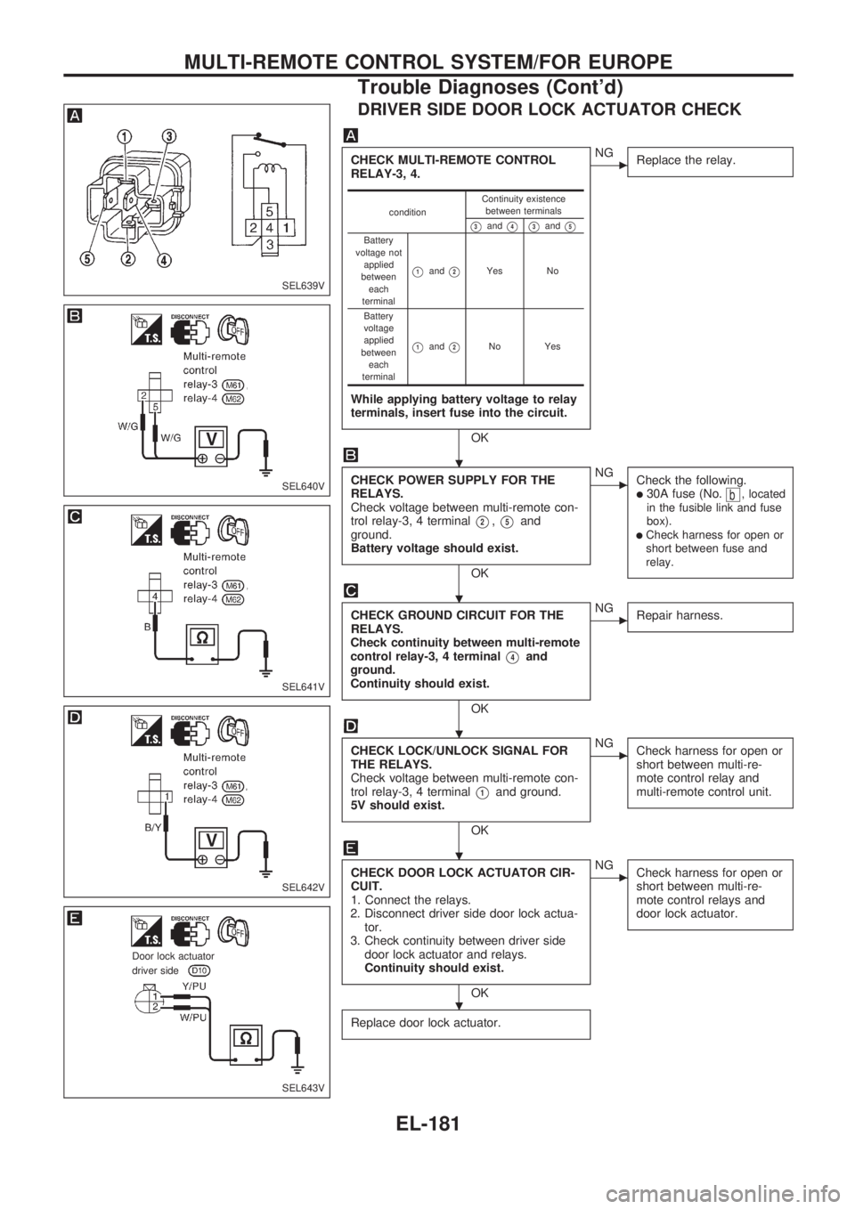
DRIVER SIDE DOOR LOCK ACTUATOR CHECK
CHECK MULTI-REMOTE CONTROL
RELAY-3, 4.
While applying battery voltage to relay
terminals, insert fuse into the circuit.
OK
cNG
Replace the relay.
CHECK POWER SUPPLY FOR THE
RELAYS.
Check voltage between multi-remote con-
trol relay-3, 4 terminal
V2,V5and
ground.
Battery voltage should exist.
OK
cNG
Check the following.
l30A fuse (No.b, located
in the fusible link and fuse
box).
lCheck harness for open or
short between fuse and
relay.
CHECK GROUND CIRCUIT FOR THE
RELAYS.
Check continuity between multi-remote
control relay-3, 4 terminal
V4and
ground.
Continuity should exist.
OK
cNG
Repair harness.
CHECK LOCK/UNLOCK SIGNAL FOR
THE RELAYS.
Check voltage between multi-remote con-
trol relay-3, 4 terminal
V1and ground.
5V should exist.
OK
cNG
Check harness for open or
short between multi-re-
mote control relay and
multi-remote control unit.
CHECK DOOR LOCK ACTUATOR CIR-
CUIT.
1. Connect the relays.
2. Disconnect driver side door lock actua-
tor.
3. Check continuity between driver side
door lock actuator and relays.
Continuity should exist.
OK
cNG
Check harness for open or
short between multi-re-
mote control relays and
door lock actuator.
Replace door lock actuator.
conditionContinuity existence
between terminals
V3andV4V3andV5
Battery
voltage not
applied
between
each
terminal
V1andV2Yes No
Battery
voltage
applied
between
each
terminal
V1andV2No Yes
SEL639V
SEL640V
SEL641V
SEL642V
SEL643V
.Door lock actuator.driver side
.
.
.
.
.
MULTI-REMOTE CONTROL SYSTEM/FOR EUROPE
Trouble Diagnoses (Cont'd)
EL-181
Page 581 of 1659
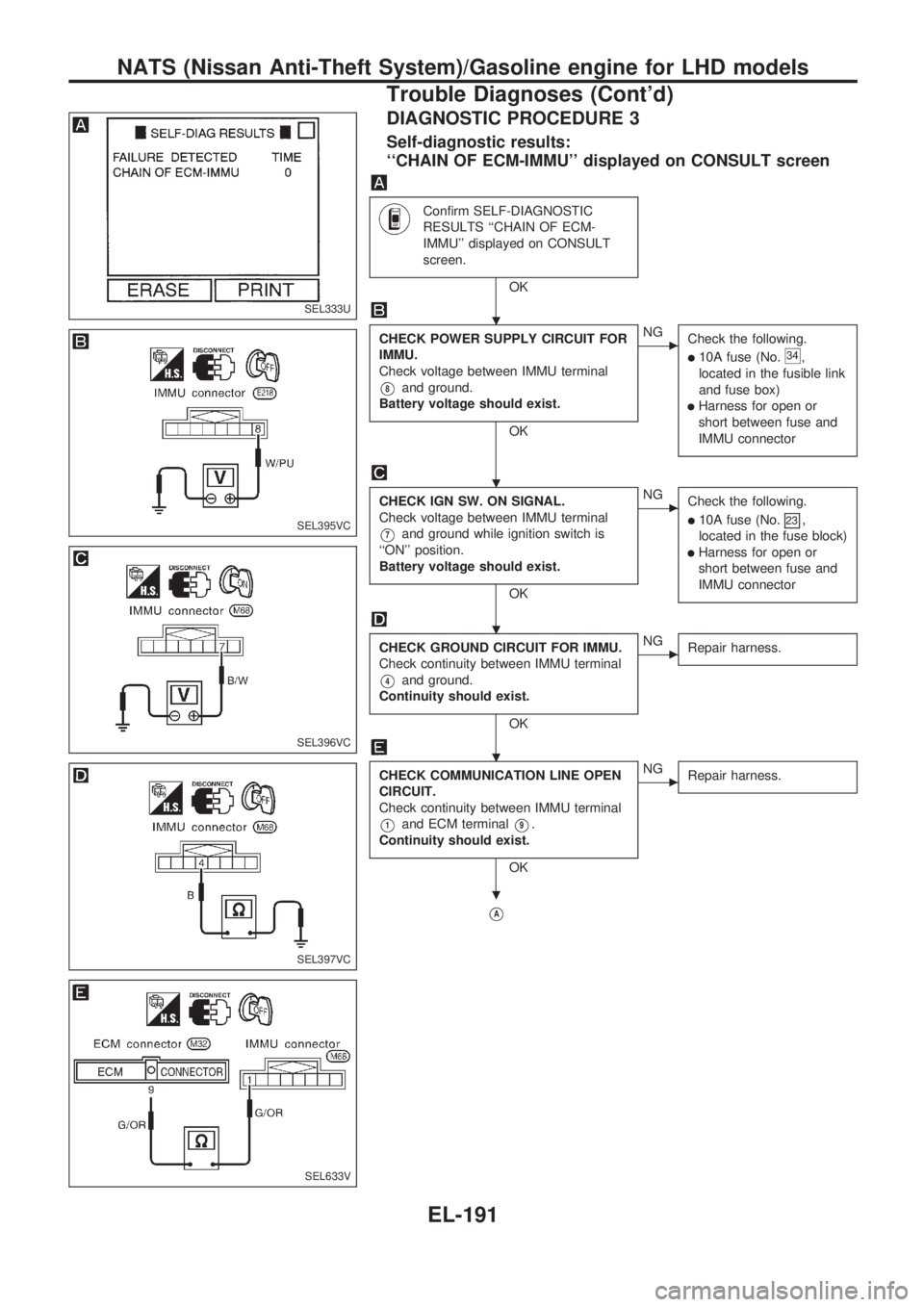
DIAGNOSTIC PROCEDURE 3
Self-diagnostic results:
``CHAIN OF ECM-IMMU'' displayed on CONSULT screen
Confirm SELF-DIAGNOSTIC
RESULTS ``CHAIN OF ECM-
IMMU'' displayed on CONSULT
screen.
OK
CHECK POWER SUPPLY CIRCUIT FOR
IMMU.
Check voltage between IMMU terminal
V8and ground.
Battery voltage should exist.
OK
cNG
Check the following.
l10A fuse (No.34,
located in the fusible link
and fuse box)
lHarness for open or
short between fuse and
IMMU connector
CHECK IGN SW. ON SIGNAL.
Check voltage between IMMU terminal
V7and ground while ignition switch is
``ON'' position.
Battery voltage should exist.
OK
cNG
Check the following.
l10A fuse (No.23,
located in the fuse block)
lHarness for open or
short between fuse and
IMMU connector
CHECK GROUND CIRCUIT FOR IMMU.
Check continuity between IMMU terminal
V4and ground.
Continuity should exist.
OK
cNG
Repair harness.
CHECK COMMUNICATION LINE OPEN
CIRCUIT.
Check continuity between IMMU terminal
V1and ECM terminalV9.
Continuity should exist.
OK
cNG
Repair harness.
VA
SEL333U
SEL395VC
SEL396VC
SEL397VC
SEL633V
.
.
.
.
.
NATS (Nissan Anti-Theft System)/Gasoline engine for LHD models
Trouble Diagnoses (Cont'd)
EL-191
Page 605 of 1659
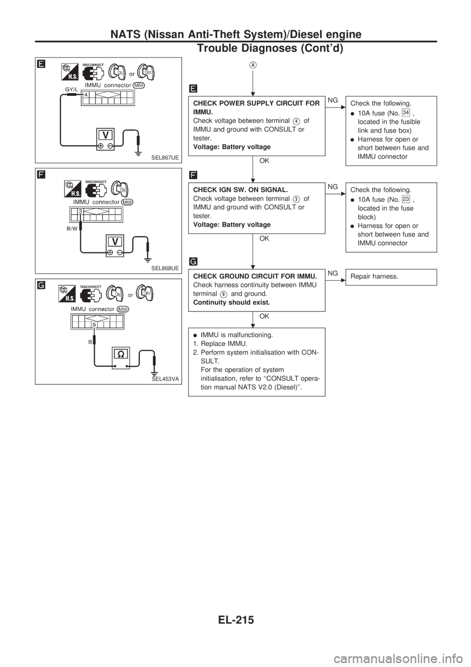
VA
CHECK POWER SUPPLY CIRCUIT FOR
IMMU.
Check voltage between terminal
V4of
IMMU and ground with CONSULT or
tester.
Voltage: Battery voltage
OK
cNG
Check the following.
l10A fuse (No.34,
located in the fusible
link and fuse box)
lHarness for open or
short between fuse and
IMMU connector
CHECK IGN SW. ON SIGNAL.
Check voltage between terminal
V3of
IMMU and ground with CONSULT or
tester.
Voltage: Battery voltage
OK
cNG
Check the following.
l10A fuse (No.23,
located in the fuse
block)
lHarness for open or
short between fuse and
IMMU connector
CHECK GROUND CIRCUIT FOR IMMU.
Check harness continuity between IMMU
terminal
V9and ground.
Continuity should exist.
OK
cNG
Repair harness.
lIMMU is malfunctioning.
1. Replace IMMU.
2. Perform system initialisation with CON-
SULT.
For the operation of system
initialisation, refer to ``CONSULT opera-
tion manual NATS V2.0 (Diesel)''.
SEL867UE
SEL868UE
SEL453VA
.
.
.
.
NATS (Nissan Anti-Theft System)/Diesel engine
Trouble Diagnoses (Cont'd)
EL-215