1998 NISSAN PICK-UP lights
[x] Cancel search: lightsPage 188 of 1659
Introduction
The ECM (ECCS control module) has an on board diagnostic system, which detects malfunctions related to
engine sensors or actuators. Self-diagnosis items are listed in ``DIAGNOSTIC TROUBLE CODE INDEX'',
EC-1.
The malfunction indicator lamp (MIL) on the instrument panel lights up when a malfunction is detected, or
when the ECM enters fail-safe mode (Refer to EC-61).
Diagnostic Trouble Code (DTC)
HOW TO CONFIRM MALFUNCTION ITEMS
Malfunction items can be confirmed by the following methods.
1. The number of blinks of the malfunction indicator lamp in the Diagnostic Test Mode II (Self- Diag-
nostic Results) indicates the DTC. Examples: 11, 21 etc.
2. CONSULT displays the malfunctioning component or system in ``SELF DIAGNOSTIC RESULTS''
mode.
lOutput of a DTC indicates a malfunction. However, Mode II does not indicate whether the mal-
function is still occurring or has occurred in the past and has returned to normal.
CONSULT can identify malfunction status as shown below. Therefore, using CONSULT (if avail-
able) is recommended.
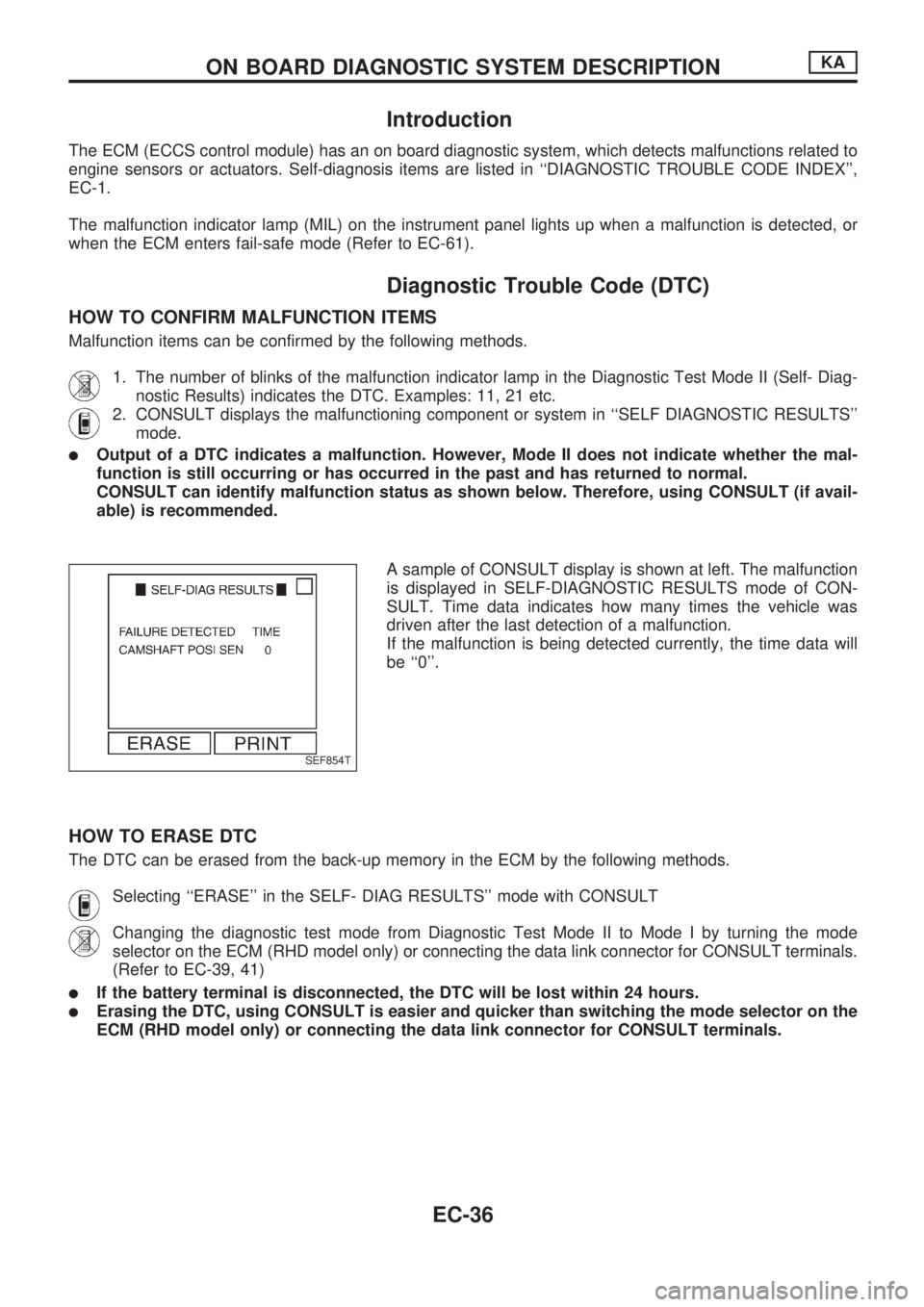
A sample of CONSULT display is shown at left. The malfunction
is displayed in SELF-DIAGNOSTIC RESULTS mode of CON-
SULT. Time data indicates how many times the vehicle was
driven after the last detection of a malfunction.
If the malfunction is being detected currently, the time data will
be ``0''.
HOW TO ERASE DTC
The DTC can be erased from the back-up memory in the ECM by the following methods.
Selecting ``ERASE'' in the SELF- DIAG RESULTS'' mode with CONSULT
Changing the diagnostic test mode from Diagnostic Test Mode II to Mode I by turning the mode
selector on the ECM (RHD model only) or connecting the data link connector for CONSULT terminals.
(Refer to EC-39, 41)
lIf the battery terminal is disconnected, the DTC will be lost within 24 hours.
lErasing the DTC, using CONSULT is easier and quicker than switching the mode selector on the
ECM (RHD model only) or connecting the data link connector for CONSULT terminals.
SEF854T
ON BOARD DIAGNOSTIC SYSTEM DESCRIPTIONKA
EC-36
Page 208 of 1659
Work Flow
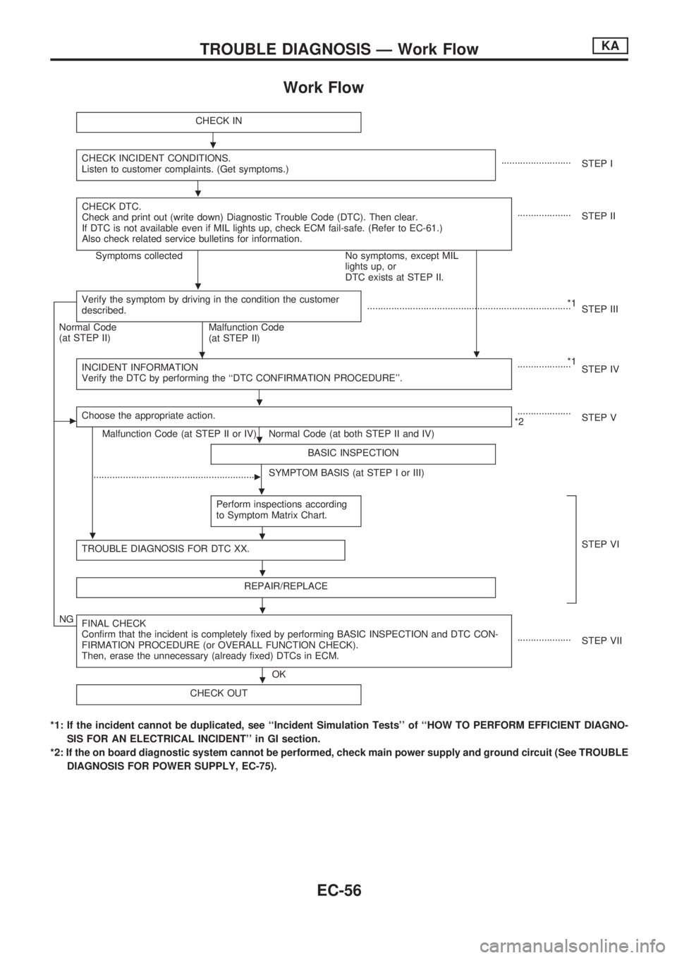
CHECK IN
CHECK INCIDENT CONDITIONS.
Listen to customer complaints. (Get symptoms.)..........................
STEP I
CHECK DTC.
Check and print out (write down) Diagnostic Trouble Code (DTC). Then clear.
If DTC is not available even if MIL lights up, check ECM fail-safe. (Refer to EC-61.)
Also check related service bulletins for information.
....................
STEP II
Symptoms collected No symptoms, except MIL
lights up, or
DTC exists at STEP II.
Verify the symptom by driving in the condition the customer
described.
.
*1
............................................................................
STEP III
Normal Code
(at STEP II)
Malfunction Code
(at STEP II)
INCIDENT INFORMATION
Verify the DTC by performing the ``DTC CONFIRMATION PROCEDURE''.
*1
....................
STEP IV
cChoose the appropriate action.
Malfunction Code (at STEP II or IV) Normal Code (at both STEP II and IV)....................
*2STEP V
BASIC INSPECTION
SYMPTOM BASIS (at STEP I or III)
............................................................c
Perform inspections according
to Symptom Matrix Chart.
.
TROUBLE DIAGNOSIS FOR DTC XX.STEP VI
REPAIR/REPLACE
NGFINAL CHECK
Confirm that the incident is completely fixed by performing BASIC INSPECTION and DTC CON-
FIRMATION PROCEDURE (or OVERALL FUNCTION CHECK).
Then, erase the unnecessary (already fixed) DTCs in ECM.
OK....................
STEP VII
CHECK OUT
*1: If the incident cannot be duplicated, see ``Incident Simulation Tests'' of ``HOW TO PERFORM EFFICIENT DIAGNO-
SIS FOR AN ELECTRICAL INCIDENT'' in GI section.
*2: If the on board diagnostic system cannot be performed, check main power supply and ground circuit (See TROUBLE
DIAGNOSIS FOR POWER SUPPLY, EC-75).
.
.
.
.
.
.
.
.
.
.
.
TROUBLE DIAGNOSIS Ð Work FlowKA
EC-56
Page 213 of 1659
Fail-Safe Chart
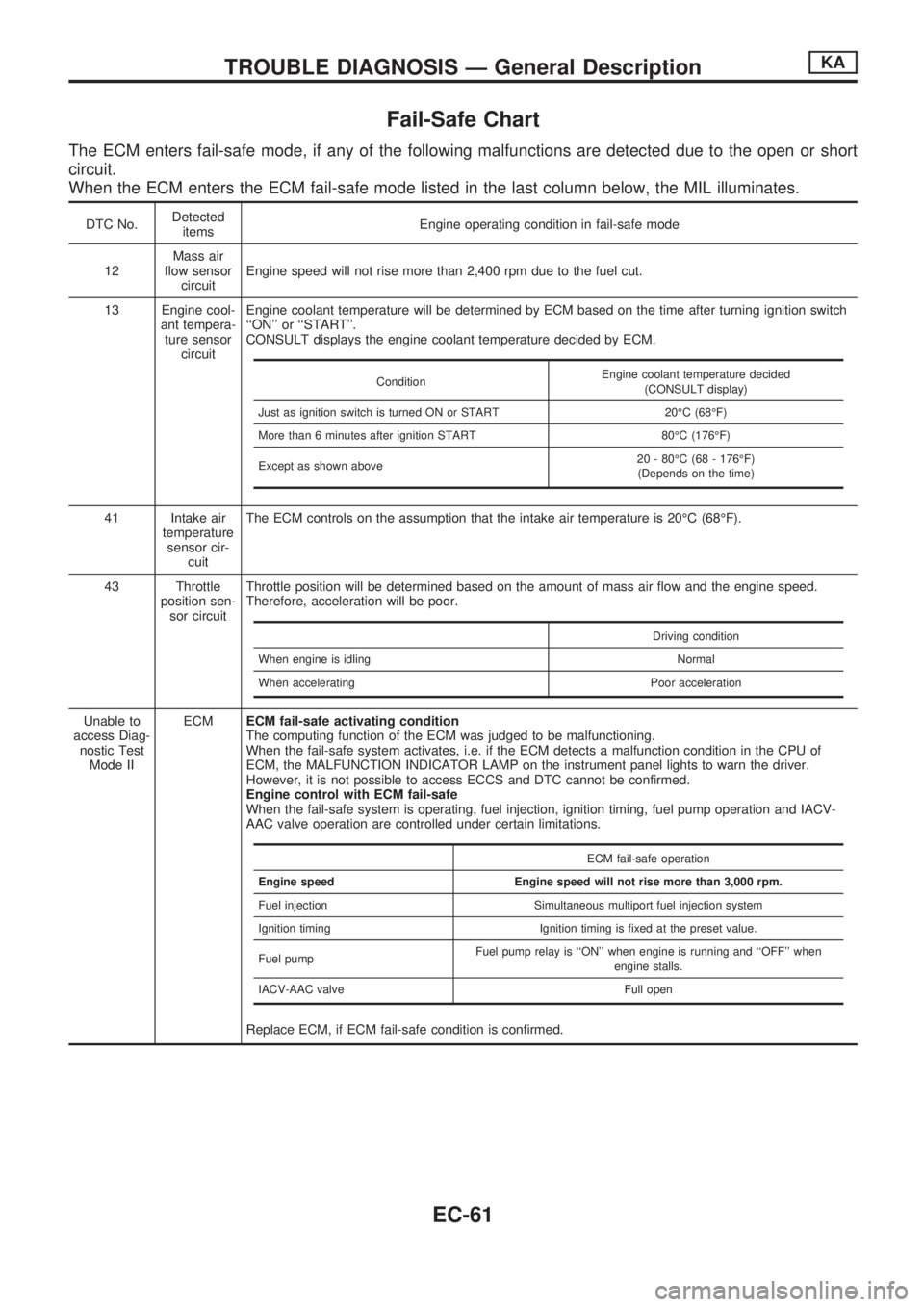
The ECM enters fail-safe mode, if any of the following malfunctions are detected due to the open or short
circuit.
When the ECM enters the ECM fail-safe mode listed in the last column below, the MIL illuminates.
DTC No.Detected
itemsEngine operating condition in fail-safe mode
12Mass air
flow sensor
circuitEngine speed will not rise more than 2,400 rpm due to the fuel cut.
13 Engine cool-
ant tempera-
ture sensor
circuitEngine coolant temperature will be determined by ECM based on the time after turning ignition switch
``ON'' or ``START''.
CONSULT displays the engine coolant temperature decided by ECM.
41 Intake air
temperature
sensor cir-
cuitThe ECM controls on the assumption that the intake air temperature is 20ÉC (68ÉF).
43 Throttle
position sen-
sor circuitThrottle position will be determined based on the amount of mass air flow and the engine speed.
Therefore, acceleration will be poor.
Unable to
access Diag-
nostic Test
Mode IIECMECM fail-safe activating condition
The computing function of the ECM was judged to be malfunctioning.
When the fail-safe system activates, i.e. if the ECM detects a malfunction condition in the CPU of
ECM, the MALFUNCTION INDICATOR LAMP on the instrument panel lights to warn the driver.
However, it is not possible to access ECCS and DTC cannot be confirmed.
Engine control with ECM fail-safe
When the fail-safe system is operating, fuel injection, ignition timing, fuel pump operation and IACV-
AAC valve operation are controlled under certain limitations.
Replace ECM, if ECM fail-safe condition is confirmed.
ConditionEngine coolant temperature decided
(CONSULT display)
Just as ignition switch is turned ON or START 20ÉC (68ÉF)
More than 6 minutes after ignition START 80ÉC (176ÉF)
Except as shown above20 - 80ÉC (68 - 176ÉF)
(Depends on the time)
Driving condition
When engine is idling Normal
When accelerating Poor acceleration
ECM fail-safe operation
Engine speed Engine speed will not rise more than 3,000 rpm.
Fuel injection Simultaneous multiport fuel injection system
Ignition timing Ignition timing is fixed at the preset value.
Fuel pumpFuel pump relay is ``ON'' when engine is running and ``OFF'' when
engine stalls.
IACV-AAC valve Full open
TROUBLE DIAGNOSIS Ð General DescriptionKA
EC-61
Page 384 of 1659
General Specifications
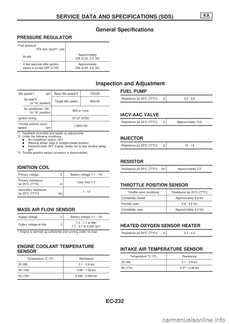
PRESSURE REGULATOR
Fuel pressure
kPa (bar, kg/cm2, psi)
At idleApproximately
235 (2.35, 2.4, 34)
A few seconds after ignition
switch is turned OFF to ONApproximately
294 (2.94, 3.0, 43)
Inspection and Adjustment
Idle speed*1 rpm Base idle speed*3 750 25
No-load*2
(in ``N'' position)Target idle speed 800 50
Air conditioner: ON
(in ``N'' position)900 or more
Ignition timing 10É 2É BTDC
Throttle position touch
speed rpm1,000 150
*1: Feedback controlled and needs no adjustments
*2: Under the following conditions:
lAir conditioner switch: OFFlSteering wheel: Kept in straight-ahead positionlElectrical load: OFF (Lights, heater fan & rear window defog-
ger)
*3: Throttle position sensor connector is disconnected.
IGNITION COIL
Primary voltage V Battery voltage (11 - 14)
Primary resistance
[at 25ÉC (77ÉF)]WLess than 1.0
Secondary resistance
[at 25ÉC (77ÉF)] kW7-13
MASS AIR FLOW SENSOR
Supply voltage V Battery voltage (11 - 14)
Output voltage at idle V1.3 - 1.7 at idle*
1.7 - 2.1 at 2,500 rpm*
*: Engine is warmed up sufficiently and running under no-load.
ENGINE COOLANT TEMPERATURE
SENSOR
Temperature ÉC (ÉF) Resistance
20 (68) 2.1 - 2.9 kW
50 (122) 0.68 - 1.00 kW
90 (194) 0.236 - 0.260 kW
FUEL PUMP
Resistance [at 25ÉC (77ÉF)]W0.2 - 5.0
IACV-AAC VALVE
Resistance [at 25ÉC (77ÉF)]WApproximately 10.0
INJECTOR
Resistance [at 25ÉC (77ÉF)]W10-14
RESISTOR
Resistance [at 25ÉC (77ÉF)] kWApproximately 2.2
THROTTLE POSITION SENSOR
Throttle valve conditions Resistance [at 25ÉC (77ÉF)]
Completely closed Approximately 0.6 kW
Partially open 0.6 - 4.0 kW
Completely open Approximately 4.0 kW
HEATED OXYGEN SENSOR HEATER
Resistance [at 25ÉC (77ÉF)]W2.3 - 4.3
INTAKE AIR TEMPERATURE SENSOR
Temperature ÉC (ÉF) Resistance
20 (68) 2.1 - 2.9 kW
80 (176) 0.27 - 0.38 kW
SERVICE DATA AND SPECIFICATIONS (SDS)KA
EC-232
Page 834 of 1659
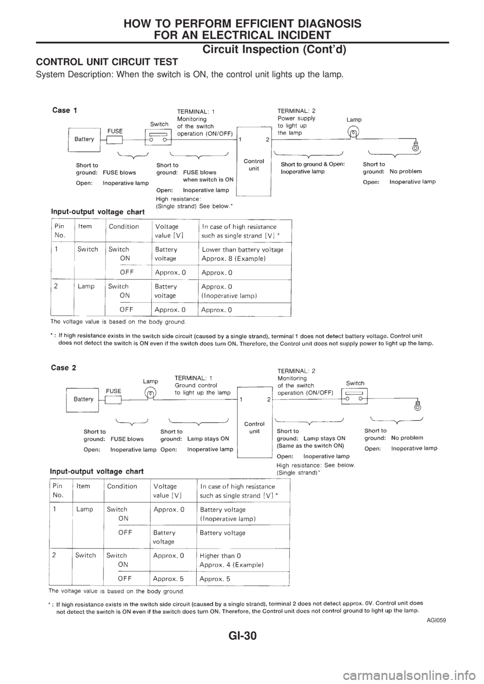
CONTROL UNIT CIRCUIT TEST
System Description: When the switch is ON, the control unit lights up the lamp.
AGI059
HOW TO PERFORM EFFICIENT DIAGNOSIS
FOR AN ELECTRICAL INCIDENT
Circuit Inspection (Cont'd)
GI-30
Page 976 of 1659
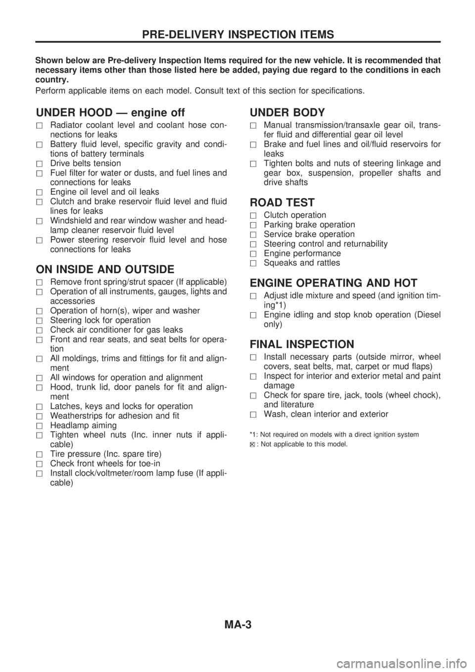
Shown below are Pre-delivery Inspection Items required for the new vehicle. It is recommended that
necessary items other than those listed here be added, paying due regard to the conditions in each
country.
Perform applicable items on each model. Consult text of this section for specifications.
UNDER HOOD Ð engine off
hRadiator coolant level and coolant hose con-
nections for leaks
hBattery fluid level, specific gravity and condi-
tions of battery terminals
hDrive belts tension
hFuel filter for water or dusts, and fuel lines and
connections for leaks
hEngine oil level and oil leaks
hClutch and brake reservoir fluid level and fluid
lines for leaks
hWindshield and rear window washer and head-
lamp cleaner reservoir fluid level
hPower steering reservoir fluid level and hose
connections for leaks
ON INSIDE AND OUTSIDE
hRemove front spring/strut spacer (If applicable)
hOperation of all instruments, gauges, lights and
accessories
hOperation of horn(s), wiper and washer
hSteering lock for operation
hCheck air conditioner for gas leaks
hFront and rear seats, and seat belts for opera-
tion
hAll moldings, trims and fittings for fit and align-
ment
hAll windows for operation and alignment
hHood, trunk lid, door panels for fit and align-
ment
hLatches, keys and locks for operation
hWeatherstrips for adhesion and fit
hHeadlamp aiming
hTighten wheel nuts (Inc. inner nuts if appli-
cable)
hTire pressure (Inc. spare tire)
hCheck front wheels for toe-in
hInstall clock/voltmeter/room lamp fuse (If appli-
cable)
UNDER BODY
hManual transmission/transaxle gear oil, trans-
fer fluid and differential gear oil level
hBrake and fuel lines and oil/fluid reservoirs for
leaks
hTighten bolts and nuts of steering linkage and
gear box, suspension, propeller shafts and
drive shafts
ROAD TEST
hClutch operation
hParking brake operation
hService brake operation
hSteering control and returnability
hEngine performance
hSqueaks and rattles
ENGINE OPERATING AND HOT
hAdjust idle mixture and speed (and ignition tim-
ing*1)
hEngine idling and stop knob operation (Diesel
only)
FINAL INSPECTION
hInstall necessary parts (outside mirror, wheel
covers, seat belts, mat, carpet or mud flaps)
hInspect for interior and exterior metal and paint
damage
hCheck for spare tire, jack, tools (wheel chock),
and literature
hWash, clean interior and exterior
*1: Not required on models with a direct ignition system
h
X: Not applicable to this model.
PRE-DELIVERY INSPECTION ITEMS
MA-3
Page 977 of 1659
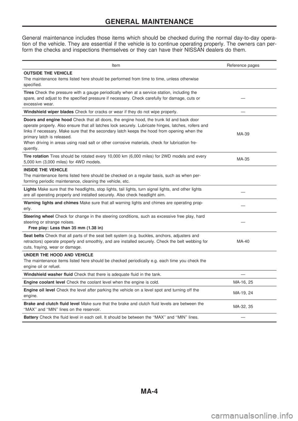
General maintenance includes those items which should be checked during the normal day-to-day opera-
tion of the vehicle. They are essential if the vehicle is to continue operating properly. The owners can per-
form the checks and inspections themselves or they can have their NISSAN dealers do them.
Item Reference pages
OUTSIDE THE VEHICLE
The maintenance items listed here should be performed from time to time, unless otherwise
specified.
TiresCheck the pressure with a gauge periodically when at a service station, including the
spare, and adjust to the specified pressure if necessary. Check carefully for damage, cuts or
excessive wear.Ð
Windshield wiper bladesCheck for cracks or wear if they do not wipe properly. Ð
Doors and engine hoodCheck that all doors, the engine hood, the trunk lid and back door
operate properly. Also ensure that all latches lock securely. Lubricate hinges, latches, rollers and
links if necessary. Make sure that the secondary latch keeps the hood from opening when the
primary latch is released.
When driving in areas using road salt or other corrosive materials, check for lubrication fre-
quently.MA-39
Tire rotationTires should be rotated every 10,000 km (6,000 miles) for 2WD models and every
5,000 km (3,000 miles) for 4WD models.MA-35
INSIDE THE VEHICLE
The maintenance items listed here should be checked on a regular basis, such as when per-
forming periodic maintenance, cleaning the vehicle, etc.
LightsMake sure that the headlights, stop lights, tail lights, turn signal lights, and other lights
are all operating properly and installed securely. Also check headlight aim.Ð
Warning lights and chimesMake sure that all warning lights and chimes are operating prop-
erly.Ð
Steering wheelCheck for change in the steering conditions, such as excessive free play, hard
steering or strange noises.
Free play: Less than 35 mm (1.38 in)Ð
Seat beltsCheck that all parts of the seat belt system (e.g. buckles, anchors, adjusters and
retractors) operate properly and smoothly, and are installed securely. Check the belt webbing for
cuts, fraying, wear or damage.MA-40
UNDER THE HOOD AND VEHICLE
The maintenance items listed here should be checked periodically e.g. each time you check the
engine oil or refuel.
Windshield washer fluidCheck that there is adequate fluid in the tank. Ð
Engine coolant levelCheck the coolant level when the engine is cold. MA-16, 25
Engine oil levelCheck the level after parking the vehicle on a level spot and turning off the
engine.MA-19, 24
Brake and clutch fluid levelMake sure that the brake and clutch fluid levels are between the
``MAX'' and ``MIN'' lines on the reservoir.MA-32, 35
BatteryCheck the fluid level in each cell. It should be between the ``MAX'' and ``MIN'' lines. Ð
GENERAL MAINTENANCE
MA-4
Page 1003 of 1659
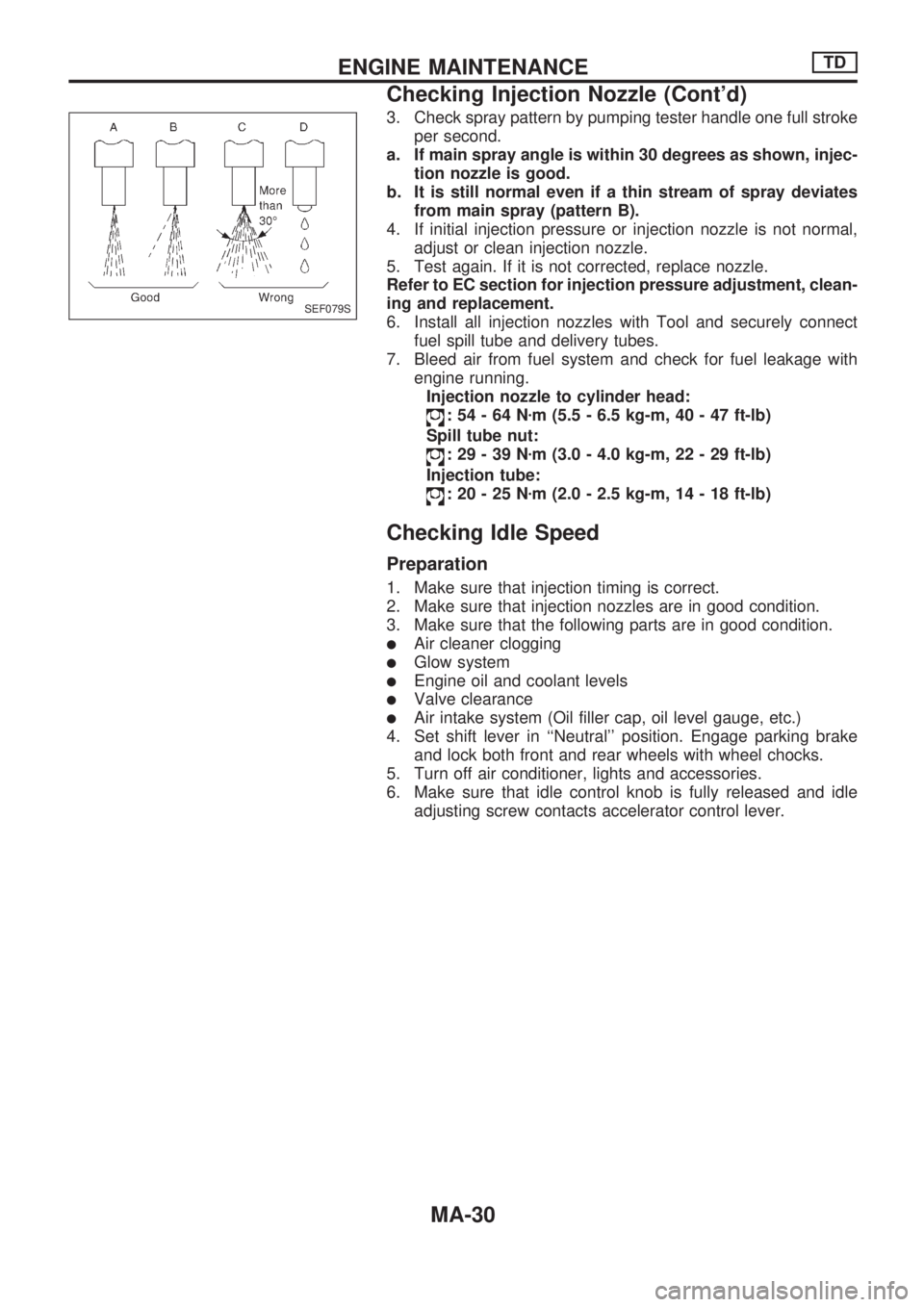
3. Check spray pattern by pumping tester handle one full stroke
per second.
a. If main spray angle is within 30 degrees as shown, injec-
tion nozzle is good.
b. It is still normal even if a thin stream of spray deviates
from main spray (pattern B).
4. If initial injection pressure or injection nozzle is not normal,
adjust or clean injection nozzle.
5. Test again. If it is not corrected, replace nozzle.
Refer to EC section for injection pressure adjustment, clean-
ing and replacement.
6. Install all injection nozzles with Tool and securely connect
fuel spill tube and delivery tubes.
7. Bleed air from fuel system and check for fuel leakage with
engine running.
Injection nozzle to cylinder head:
:54-64Nzm (5.5 - 6.5 kg-m, 40 - 47 ft-lb)
Spill tube nut:
:29-39Nzm (3.0 - 4.0 kg-m, 22 - 29 ft-lb)
Injection tube:
:20-25Nzm (2.0 - 2.5 kg-m, 14 - 18 ft-lb)
Checking Idle Speed
Preparation
1. Make sure that injection timing is correct.
2. Make sure that injection nozzles are in good condition.
3. Make sure that the following parts are in good condition.
lAir cleaner clogging
lGlow system
lEngine oil and coolant levels
lValve clearance
lAir intake system (Oil filler cap, oil level gauge, etc.)
4. Set shift lever in ``Neutral'' position. Engage parking brake
and lock both front and rear wheels with wheel chocks.
5. Turn off air conditioner, lights and accessories.
6. Make sure that idle control knob is fully released and idle
adjusting screw contacts accelerator control lever.
SEF079S
ENGINE MAINTENANCETD
Checking Injection Nozzle (Cont'd)
MA-30