Page 143 of 1659

lAll dimensions indicated in figures are actual ones.
lWhen using a tracking gauge, adjust both pointers to equal length. Make sure there is no free play.
lWhen a measuring tape is used, check to be sure there is no elongation, twisting or bending.
lMeasurements should be taken at the center of the mounting holes.
lAll measurements and mounting hole diameters are expressed in millimeters (mm).
lAn asterisk (*) following the value at the measuring point indicates that the measuring point on the other
side is symmetrically the same value.
lThe coordinates of the measurement points are the distances measured from the respective dimension
lines in the directions of ``x'', ``y'' and ``z''.
Dimension lines: ``x'' line Ð Center line of vehicle
``y'' line Ð Center line of front axle (Any measurement point in front of the dimension
line refers to a minus ``Ð'' value.)
``z'' line Ð Datum line (Any measurement point under the dimension line refers to a
minus ``Ð'' value.)
2W.SB: Short wheelbase (2WD)
2W.LB
: Long wheelbase (2WD)
4W.LB
: Long wheelbase (4WD)
BODY ALIGNMENT
BT-43
Page 146 of 1659
Underbody
MEASUREMENT
2WD (Short wheelbase) models
SBT461
BODY ALIGNMENT
BT-46
Page 147 of 1659
MEASUREMENT POINTS
2WD (Short wheelbase) models
SBT462
BODY ALIGNMENT
Underbody (Cont'd)
BT-47
Page 148 of 1659
MEASUREMENT
2WDz4WD (Long wheelbase) models
SBT463
BODY ALIGNMENT
Underbody (Cont'd)
BT-48
Page 149 of 1659
MEASUREMENT POINTS
2WD4WD (Long wheelbase) models
SBT464
BODY ALIGNMENT
Underbody (Cont'd)
BT-49
Page 765 of 1659

FRONT AXLE &
FRONT SUSPENSION
SECTION
FA
CONTENTS
PRECAUTIONS AND PREPARATION..................... 1
Precautions ............................................................ 1
Special Service Tools ............................................ 1
Commercial Service Tools ..................................... 2
FRONT AXLE AND FRONT SUSPENSION............. 3
ON-VEHICLE SERVICE............................................ 5
Front Axle and Front Suspension Parts ................ 5
Front Wheel Bearing .............................................. 5
Front Wheel Alignment .......................................... 7
Drive Shaft ........................................................... 11
FRONT AXLE.......................................................... 12
Manual-lock Free-running Hub - 4WD - .............. 14
Auto-lock Free-running Hub - 4WD -................... 15
Removal ............................................................... 15
Installation ............................................................ 15Wheel Hub and Rotor Disc .................................. 16
Knuckle Spindle ................................................... 18
Drive Shaft - 4WD - ............................................. 21
FRONT SUSPENSION............................................ 26
Shock Absorber ................................................... 28
Torsion Bar Spring ............................................... 28
Stabilizer Bar........................................................ 31
Upper Link............................................................ 31
Tension Rod......................................................... 33
Lower Link............................................................ 33
Upper Ball Joint and Lower Ball Joint ................. 34
SERVICE DATA AND SPECIFICATIONS (SDS)... 35
General Specifications ......................................... 35
Inspection and Adjustment .................................. 35
FA
Page 766 of 1659

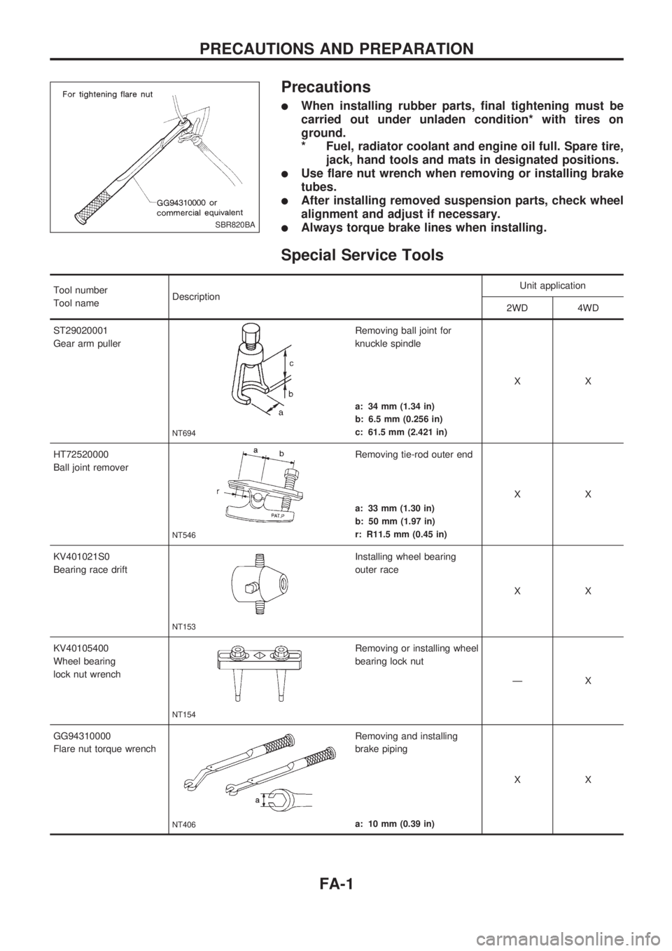
Precautions
lWhen installing rubber parts, final tightening must be
carried out under unladen condition* with tires on
ground.
* Fuel, radiator coolant and engine oil full. Spare tire,
jack, hand tools and mats in designated positions.
lUse flare nut wrench when removing or installing brake
tubes.
lAfter installing removed suspension parts, check wheel
alignment and adjust if necessary.
lAlways torque brake lines when installing.
Special Service Tools
Tool number
Tool nameDescriptionUnit application
2WD 4WD
ST29020001
Gear arm puller
NT694
Removing ball joint for
knuckle spindle
XX
a: 34 mm (1.34 in)
b: 6.5 mm (0.256 in)
c: 61.5 mm (2.421 in)
HT72520000
Ball joint remover
NT546
Removing tie-rod outer end
XX
a: 33 mm (1.30 in)
b: 50 mm (1.97 in)
r: R11.5 mm (0.45 in)
KV401021S0
Bearing race drift
NT153
Installing wheel bearing
outer race
XX
KV40105400
Wheel bearing
lock nut wrench
NT154
Removing or installing wheel
bearing lock nut
ÐX
GG94310000
Flare nut torque wrench
NT406
Removing and installing
brake piping
XX
a: 10 mm (0.39 in)
SBR820BA
PRECAUTIONS AND PREPARATION
FA-1
Page 772 of 1659

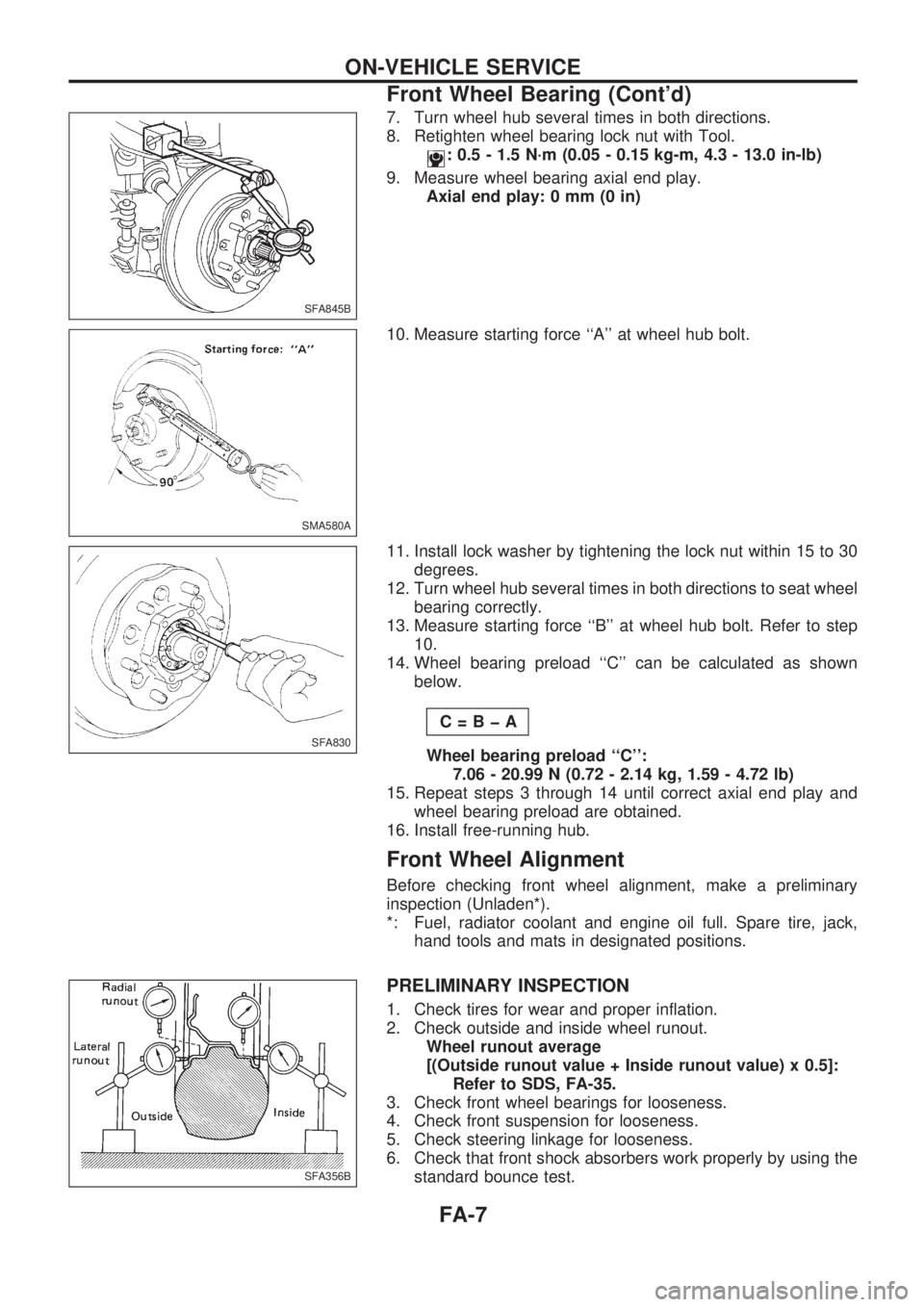
7. Turn wheel hub several times in both directions.
8. Retighten wheel bearing lock nut with Tool.
: 0.5 - 1.5 N´m (0.05 - 0.15 kg-m, 4.3 - 13.0 in-lb)
9. Measure wheel bearing axial end play.
Axial end play: 0 mm (0 in)
10. Measure starting force ``A'' at wheel hub bolt.
11. Install lock washer by tightening the lock nut within 15 to 30
degrees.
12. Turn wheel hub several times in both directions to seat wheel
bearing correctly.
13. Measure starting force ``B'' at wheel hub bolt. Refer to step
10.
14. Wheel bearing preload ``C'' can be calculated as shown
below.
C=BþA
Wheel bearing preload ``C'':
7.06 - 20.99 N (0.72 - 2.14 kg, 1.59 - 4.72 lb)
15. Repeat steps 3 through 14 until correct axial end play and
wheel bearing preload are obtained.
16. Install free-running hub.
Front Wheel Alignment
Before checking front wheel alignment, make a preliminary
inspection (Unladen*).
*: Fuel, radiator coolant and engine oil full. Spare tire, jack,
hand tools and mats in designated positions.
PRELIMINARY INSPECTION
1. Check tires for wear and proper inflation.
2. Check outside and inside wheel runout.
Wheel runout average
[(Outside runout value + Inside runout value) x 0.5]:
Refer to SDS, FA-35.
3. Check front wheel bearings for looseness.
4. Check front suspension for looseness.
5. Check steering linkage for looseness.
6. Check that front shock absorbers work properly by using the
standard bounce test.
SFA845B
SMA580A
SFA830
SFA356B
ON-VEHICLE SERVICE
Front Wheel Bearing (Cont'd)
FA-7