1998 NISSAN PICK-UP parking brake
[x] Cancel search: parking brakePage 3 of 1659
BRAKE SYSTEM
SECTIONBR
CONTENTS
PRECAUTIONS AND PREPARATION..................... 1
Supplemental Restraint System (SRS) ``AIR
BAG'' (4WD models).............................................. 1
Supplemental Restraint System (SRS) ``AIR
BAG'' (2WD models).............................................. 1
Precautions for Brake System ............................... 1
Special Service Tools ............................................ 2
Commercial Service Tools ..................................... 2
CHECK AND ADJUSTMENT.................................... 3
Checking Brake Fluid Level ................................... 3
Checking Brake Line.............................................. 3
Changing Brake Fluid ............................................ 3
Bleeding Brake System ......................................... 4
BRAKE HYDRAULIC LINE....................................... 5
CONTROL VALVE..................................................... 7
Load Sensing Valve ............................................... 7
BRAKE PEDAL AND BRACKET............................ 10
Removal and Installation ..................................... 10
Inspection ............................................................. 11
Adjustment ........................................................... 11
MASTER CYLINDER............................................... 12
Removal ............................................................... 12
Disassembly ......................................................... 13
Inspection ............................................................. 13
Assembly.............................................................. 13
Installation ............................................................ 14
BRAKE BOOSTER.................................................. 15
On-vehicle Service ............................................... 15
Removal ............................................................... 15
Inspection ............................................................. 15
Installation ............................................................ 16
VACUUM HOSE...................................................... 17
Removal and Installation ..................................... 17Inspection ............................................................. 17
VACUUM PUMP...................................................... 19
Removal and Installation ..................................... 19
Inspection ............................................................. 19
FRONT DISC BRAKE............................................. 21
Pad Replacement ................................................ 21
Removal ............................................................... 22
Disassembly ......................................................... 23
Inspection - Caliper .............................................. 23
Inspection - Rotor ................................................ 23
Assembly.............................................................. 24
Installation ............................................................ 24
Brake Burnishing Procedure ................................ 24
REAR DRUM BRAKE............................................. 26
Removal ............................................................... 27
Inspection - Wheel Cylinder................................. 28
Wheel Cylinder Overhaul ..................................... 28
Inspection - Drum ................................................ 28
Inspection - Lining................................................ 28
Installation ............................................................ 28
PARKING BRAKE CONTROL................................ 30
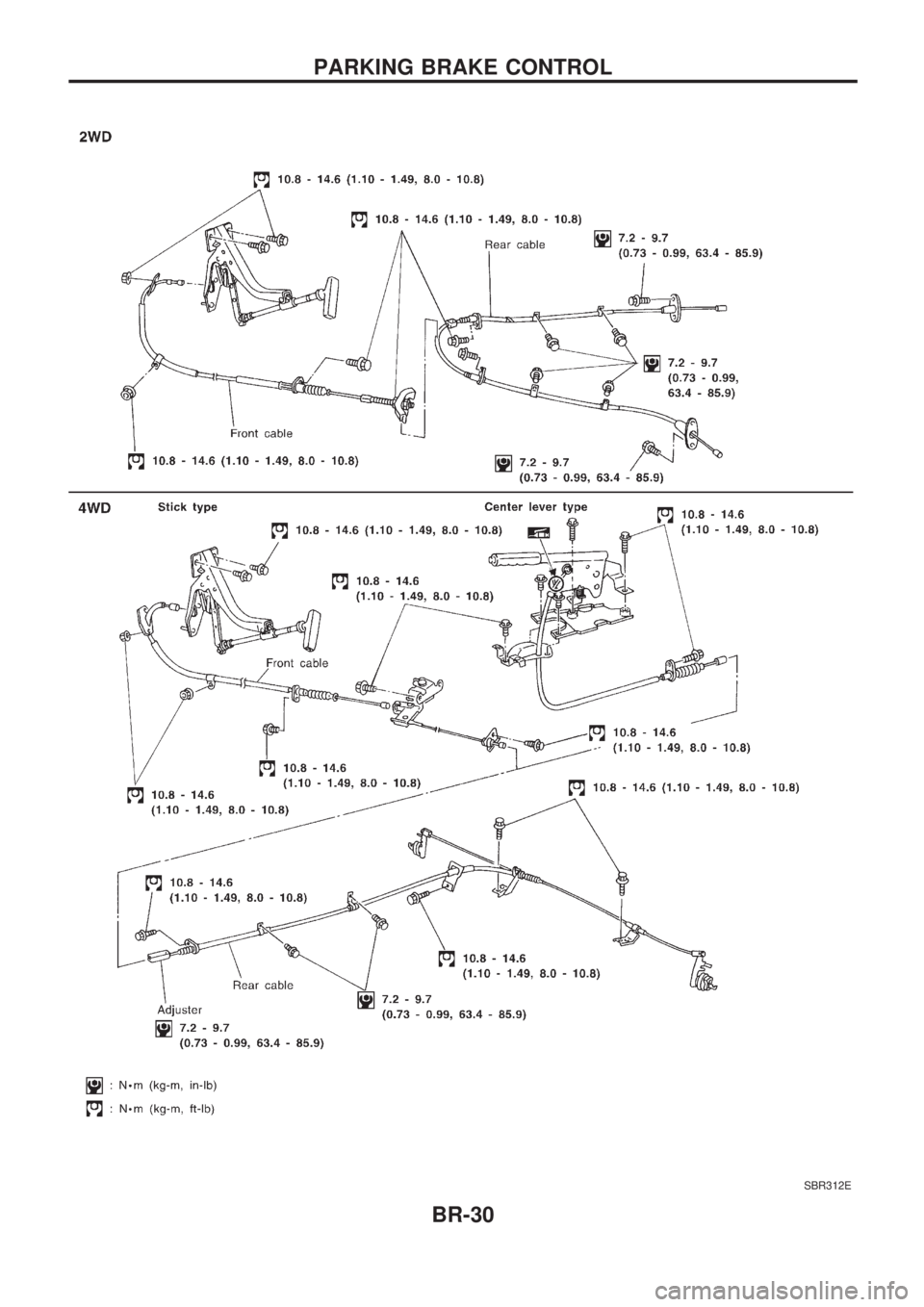
Removal and Installation ..................................... 31
Inspection ............................................................. 31
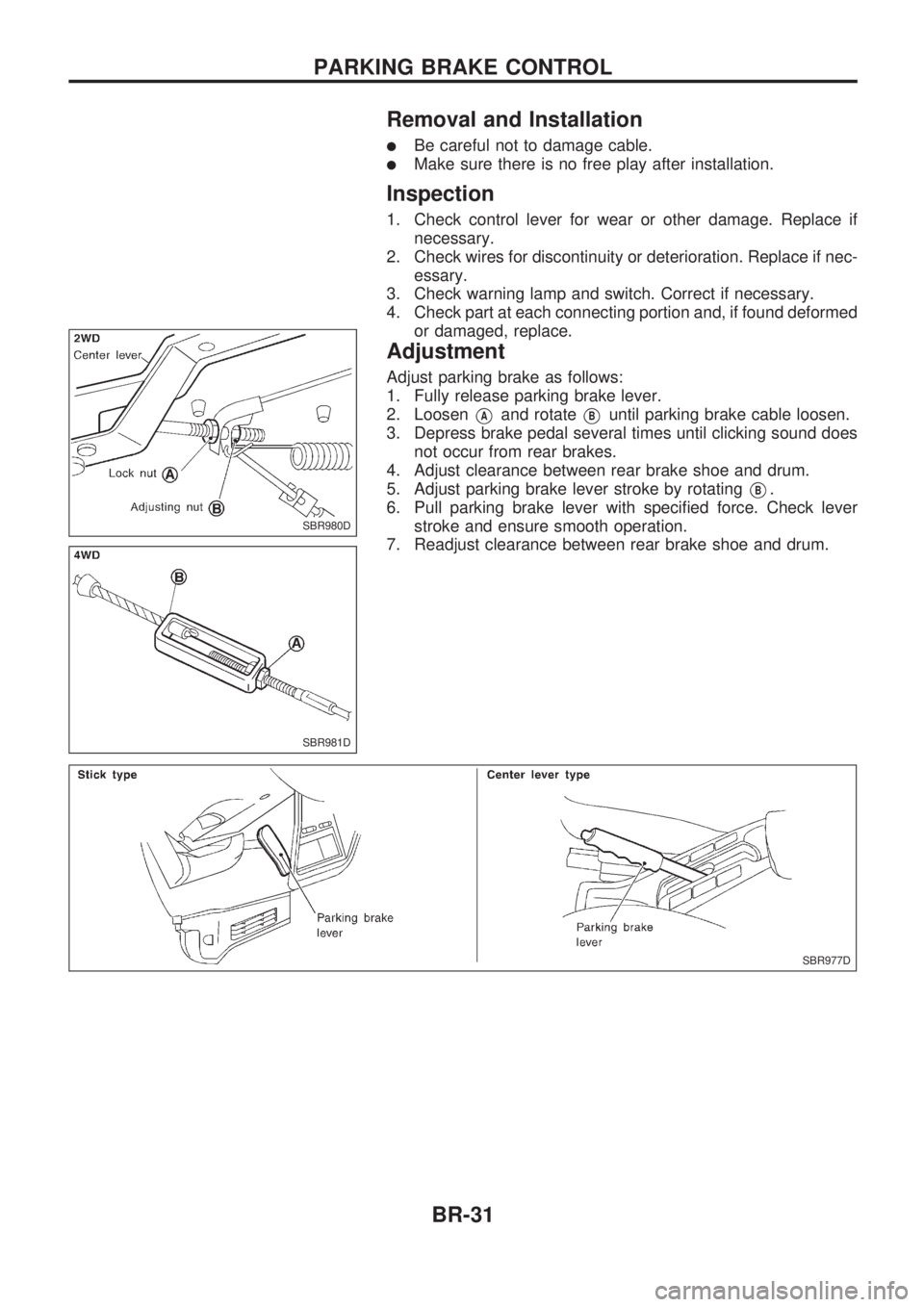
Adjustment ........................................................... 31
ANTI-LOCK BRAKE SYSTEM................................ 32
Purpose ................................................................ 32
Operation ............................................................. 32
ABS Hydraulic Circuit .......................................... 32
System Components............................................ 33
System Description .............................................. 33
Removal and Installation ..................................... 35
TROUBLE DIAGNOSES......................................... 38
BR
Page 7 of 1659
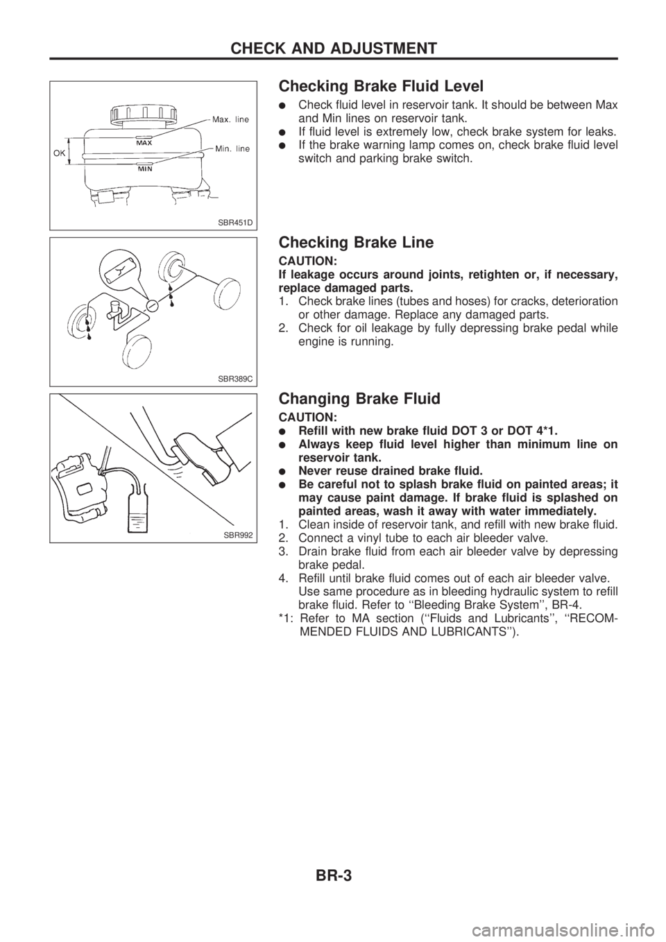
Checking Brake Fluid Level
lCheck fluid level in reservoir tank. It should be between Max
and Min lines on reservoir tank.
lIf fluid level is extremely low, check brake system for leaks.
lIf the brake warning lamp comes on, check brake fluid level
switch and parking brake switch.
Checking Brake Line
CAUTION:
If leakage occurs around joints, retighten or, if necessary,
replace damaged parts.
1. Check brake lines (tubes and hoses) for cracks, deterioration
or other damage. Replace any damaged parts.
2. Check for oil leakage by fully depressing brake pedal while
engine is running.
Changing Brake Fluid
CAUTION:
lRefill with new brake fluid DOT 3 or DOT 4*1.
lAlways keep fluid level higher than minimum line on
reservoir tank.
lNever reuse drained brake fluid.
lBe careful not to splash brake fluid on painted areas; it
may cause paint damage. If brake fluid is splashed on
painted areas, wash it away with water immediately.
1. Clean inside of reservoir tank, and refill with new brake fluid.
2. Connect a vinyl tube to each air bleeder valve.
3. Drain brake fluid from each air bleeder valve by depressing
brake pedal.
4. Refill until brake fluid comes out of each air bleeder valve.
Use same procedure as in bleeding hydraulic system to refill
brake fluid. Refer to ``Bleeding Brake System'', BR-4.
*1: Refer to MA section (``Fluids and Lubricants'', ``RECOM-
MENDED FLUIDS AND LUBRICANTS'').
SBR451D
SBR389C
SBR992
CHECK AND ADJUSTMENT
BR-3
Page 31 of 1659
Removal
WARNING:
Clean brake lining with a vacuum dust collector to minimize
the hazard of airborne materials.
CAUTION:
Make sure parking brake lever is completely released.
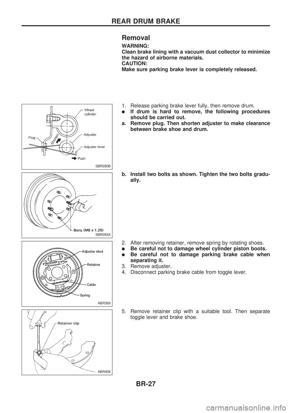
1. Release parking brake lever fully, then remove drum.
lIf drum is hard to remove, the following procedures
should be carried out.
a. Remove plug. Then shorten adjuster to make clearance
between brake shoe and drum.
b. Install two bolts as shown. Tighten the two bolts gradu-
ally.
2. After removing retainer, remove spring by rotating shoes.
lBe careful not to damage wheel cylinder piston boots.
lBe careful not to damage parking brake cable when
separating it.
3. Remove adjuster.
4. Disconnect parking brake cable from toggle lever.
5. Remove retainer clip with a suitable tool. Then separate
toggle lever and brake shoe.
SBR280B
SBR093A
ABR369
ABR408
REAR DRUM BRAKE
BR-27
Page 33 of 1659
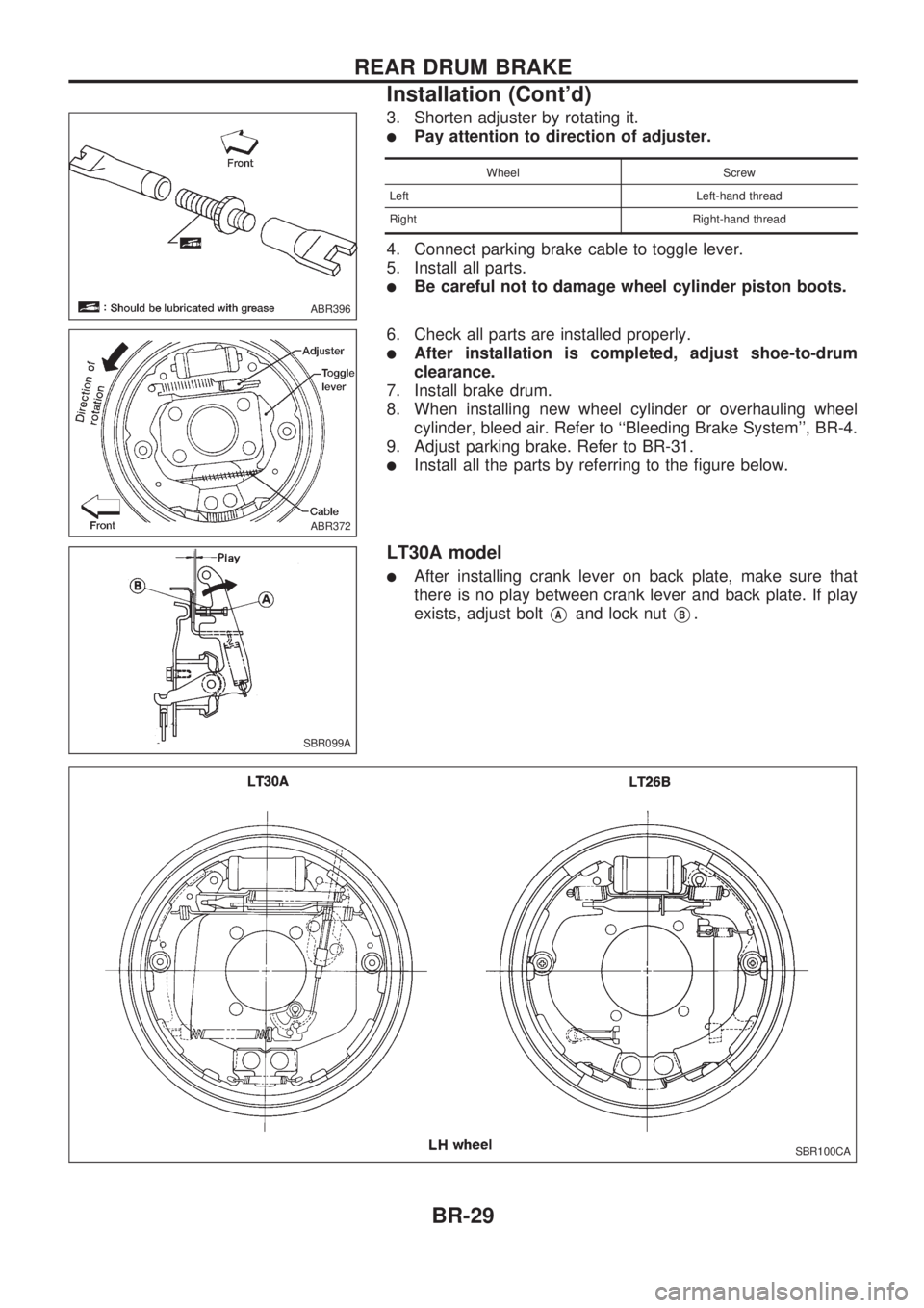
3. Shorten adjuster by rotating it.
lPay attention to direction of adjuster.
Wheel Screw
Left Left-hand thread
Right Right-hand thread
4. Connect parking brake cable to toggle lever.
5. Install all parts.
lBe careful not to damage wheel cylinder piston boots.
6. Check all parts are installed properly.
lAfter installation is completed, adjust shoe-to-drum
clearance.
7. Install brake drum.
8. When installing new wheel cylinder or overhauling wheel
cylinder, bleed air. Refer to ``Bleeding Brake System'', BR-4.
9. Adjust parking brake. Refer to BR-31.
lInstall all the parts by referring to the figure below.
LT30A model
lAfter installing crank lever on back plate, make sure that
there is no play between crank lever and back plate. If play
exists, adjust bolt
VAand lock nutVB.
ABR396
ABR372
SBR099A
SBR100CA
REAR DRUM BRAKE
Installation (Cont'd)
BR-29
Page 34 of 1659
SBR312E
PARKING BRAKE CONTROL
BR-30
Page 35 of 1659
Removal and Installation
lBe careful not to damage cable.
lMake sure there is no free play after installation.
Inspection
1. Check control lever for wear or other damage. Replace if
necessary.
2. Check wires for discontinuity or deterioration. Replace if nec-
essary.
3. Check warning lamp and switch. Correct if necessary.
4. Check part at each connecting portion and, if found deformed
or damaged, replace.
Adjustment
Adjust parking brake as follows:
1. Fully release parking brake lever.
2. Loosen
VAand rotateVBuntil parking brake cable loosen.
3. Depress brake pedal several times until clicking sound does
not occur from rear brakes.
4. Adjust clearance between rear brake shoe and drum.
5. Adjust parking brake lever stroke by rotating
VB.
6. Pull parking brake lever with specified force. Check lever
stroke and ensure smooth operation.
7. Readjust clearance between rear brake shoe and drum.
SBR980D
SBR981D
SBR977D
PARKING BRAKE CONTROL
BR-31
Page 84 of 1659

Inspection and Adjustment
DISC BRAKEUnit: mm (in)
Brake model CL28VD
Pad wear limit
Minimum thickness 2.0 (0.079)
Rotor repair limit
Minimum thickness 24.0 (0.945)
DRUM BRAKEUnit: mm (in)
Brake model LT26B LT30A
Lining wear limit
Minimum thickness 1.5 (0.059)
Drum repair limit
Maximum inner
diameter261.5 (10.30) 296.5 (11.67)
Out-of-round limit 0.15 (0.0059)
BRAKE PEDALUnit: mm (in)
Free height ``H''*
LHD 209 - 219 (8.23 - 8.62)
RHD 203 - 213 (7.99 - 8.39)
Depressed height ``D''
[under force of 490 N (50
kg, 110 lb) with engine run-
ning]120.0 (4.72)
Clearance ``C'' between
pedal stopper and threaded
end of stop lamp switch0.3 - 1.0 (0.012 - 0.039)
Pedal free play
At clevis 1.0 - 3.0 (0.039 - 0.118)
At pedal pad 4 - 12 (0.16 - 0.47)
*: Measured from surface of melt sheet to pedal pad.
PARKING BRAKE CONTROL
Control type Stick lever Center lever
Lever stroke
[under force of 196 N
(20 kg, 44 lb)]2WD 8 - 10 Ð
4WD 10-12 8-10
Lever stroke when warning
switch comes on1
SERVICE DATA AND SPECIFICATIONS (SDS)
BR-80
Page 140 of 1659
Removal
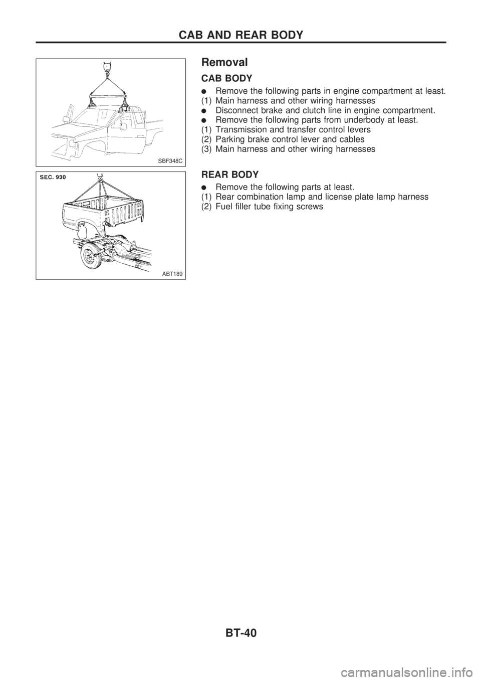
CAB BODY
lRemove the following parts in engine compartment at least.
(1) Main harness and other wiring harnesses
lDisconnect brake and clutch line in engine compartment.
lRemove the following parts from underbody at least.
(1) Transmission and transfer control levers
(2) Parking brake control lever and cables
(3) Main harness and other wiring harnesses
REAR BODY
lRemove the following parts at least.
(1) Rear combination lamp and license plate lamp harness
(2) Fuel filler tube fixing screws
SBF348C
ABT189
CAB AND REAR BODY
BT-40