1998 NISSAN PICK-UP instrument panel
[x] Cancel search: instrument panelPage 57 of 1659
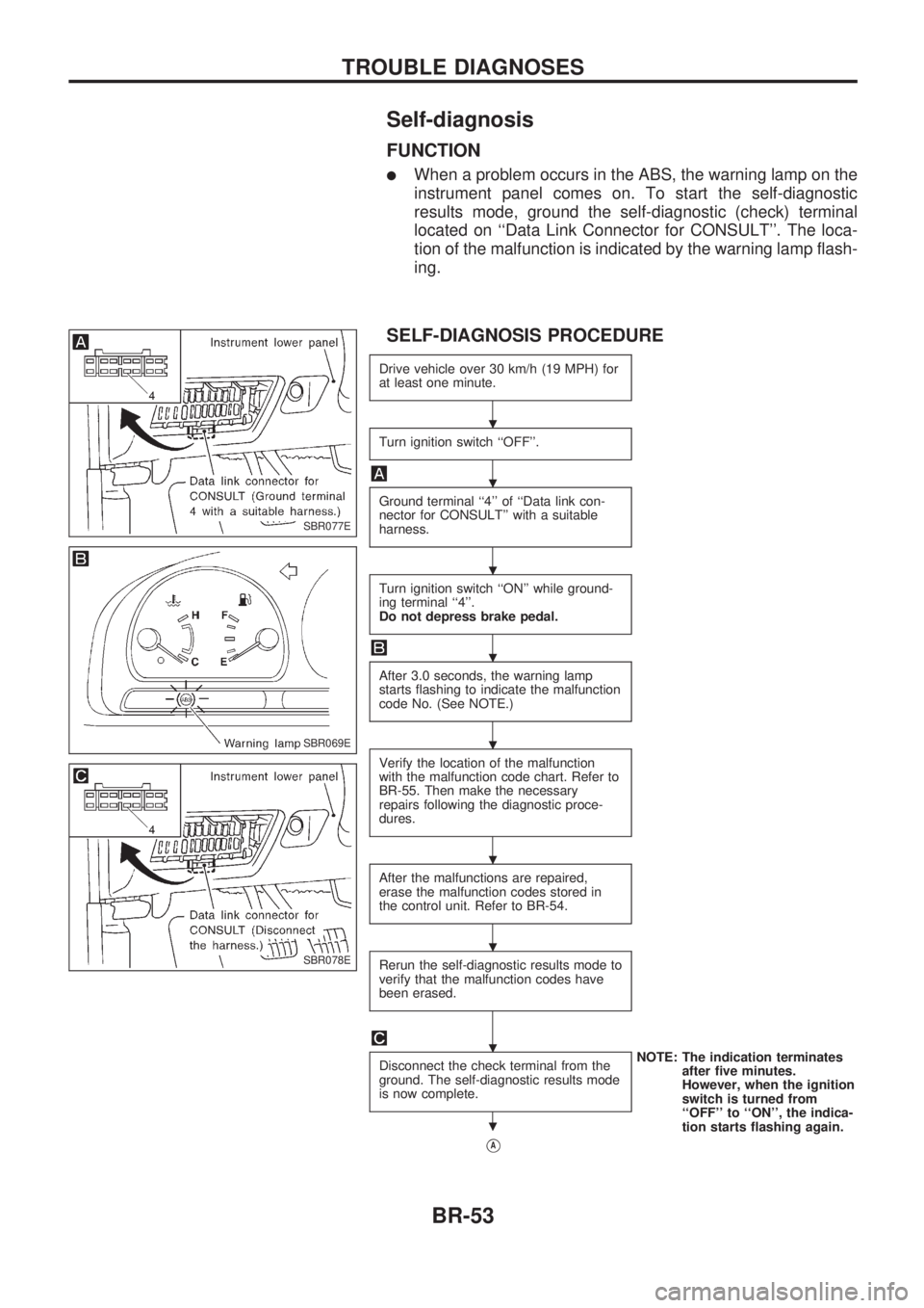
Self-diagnosis
FUNCTION
lWhen a problem occurs in the ABS, the warning lamp on the
instrument panel comes on. To start the self-diagnostic
results mode, ground the self-diagnostic (check) terminal
located on ``Data Link Connector for CONSULT''. The loca-
tion of the malfunction is indicated by the warning lamp flash-
ing.
SELF-DIAGNOSIS PROCEDURE
Drive vehicle over 30 km/h (19 MPH) for
at least one minute.
Turn ignition switch ``OFF''.
Ground terminal ``4'' of ``Data link con-
nector for CONSULT'' with a suitable
harness.
Turn ignition switch ``ON'' while ground-
ing terminal ``4''.
Do not depress brake pedal.
After 3.0 seconds, the warning lamp
starts flashing to indicate the malfunction
code No. (See NOTE.)
Verify the location of the malfunction
with the malfunction code chart. Refer to
BR-55. Then make the necessary
repairs following the diagnostic proce-
dures.
After the malfunctions are repaired,
erase the malfunction codes stored in
the control unit. Refer to BR-54.
Rerun the self-diagnostic results mode to
verify that the malfunction codes have
been erased.
Disconnect the check terminal from the
ground. The self-diagnostic results mode
is now complete.NOTE: The indication terminates
after five minutes.
However, when the ignition
switch is turned from
``OFF'' to ``ON'', the indica-
tion starts flashing again.
VA
SBR077E
SBR069E
SBR078E
.
.
.
.
.
.
.
.
.
TROUBLE DIAGNOSES
BR-53
Page 100 of 1659
BODY & TRIM
SECTIONBT
CONTENTS
PRECAUTIONS......................................................... 1
Service Notice ........................................................ 1
Supplemental Restraint System (SRS) ``AIR
BAG'' (4WD models).............................................. 1
Supplemental Restraint System (SRS) ``AIR
BAG'' (2WD models).............................................. 1
GENERAL SERVICING............................................. 2
Clip and Fastener .................................................. 2
BODY END................................................................ 5
Body Front End ...................................................... 5
Body Rear End ...................................................... 8
DOOR....................................................................... 10
Front Door ............................................................ 10
Rear Door ............................................................ 11
INSTRUMENT PANEL............................................. 12
INTERIOR TRIM...................................................... 15
Side and Floor Trim ............................................. 15
Door Trim ............................................................. 18
Roof Trim ............................................................. 21EXTERIOR............................................................... 24
SEAT........................................................................ 30
Front Seat ............................................................ 30
Heated Seat ......................................................... 32
Rear Seat ............................................................. 33
Jump Seat ............................................................ 34
SUNROOF................................................................ 35
WINDSHIELD AND WINDOWS.............................. 36
Windshield............................................................ 37
Side Window ........................................................ 38
MIRROR................................................................... 39
Door Mirror ........................................................... 39
CAB AND REAR BODY.......................................... 40
Removal ............................................................... 40
Body Mounting ..................................................... 41
BODY ALIGNMENT................................................. 43
Engine Compartment ........................................... 44
Underbody............................................................ 46
.For seat belt, refer to MA and RS section.
.For wiring diagrams of body electrical systems, refer to EL section.BT
Page 101 of 1659
Service Notice
lWhen removing or installing various parts, place a cloth or padding onto the vehicle body to prevent
scratches.
lHandle trim, molding, instruments, grille, etc. carefully during removing or installing. Be careful not to soil
or damage them.
lApply sealing compound where necessary when installing parts.
lWhen applying sealing compound, be careful that the sealing compound does not protrude from parts.
lWhen replacing any metal parts (for example body outer panel, members, etc.), be sure to take rust
prevention measures.
Supplemental Restraint System (SRS) ``AIR
BAG'' (4WD models)
The Supplemental Restraint System ``AIR BAG'', used along with a seat belt, helps to reduce the risk or
severity of injury to the driver in a frontal collision. The Supplemental Restraint System consists of air bag
module (located in the center of the steering wheel), a diagnosis sensor unit, warning lamp, wiring harness
and spiral cable. Information necessary to service the system safely is included in theRS sectionof this
Service Manual.
WARNING:
lTo avoid rendering the SRS inoperative, which could increase the risk of personal injury or death
in the event of a collision which would result in air bag inflation, all maintenance must be per-
formed by an authorized NISSAN dealer.
lImproper maintenance, including incorrect removal and installation of the SRS, can lead to per-
sonal injury caused by unintentional activation of the system.
lDo not use electrical test equipment on any circuit related to the SRS unless instructed to in this
Service Manual. SRS wiring harnesses are covered with yellow insulation either just before the
harness connectors or for the complete harness, for easy identification.
Supplemental Restraint System (SRS) ``AIR
BAG'' (2WD models)
The Supplemental Restraint System ``AIR BAG'', used along with a seat belt, helps to reduce the risk or
severity of injury to the driver in a frontal collision. The Supplemental Restraint System consists of air bag
module (located in the center of the steering wheel), diagnosis sensor unit, warning lamp, wiring harness
and spiral cable. Information necessary to service the system safely is included in theRS sectionof this
Service Manual.
WARNING:
lTo avoid rendering the SRS inoperative, which could increase the risk of personal injury or death
in the event of a collision which would result in air bag inflation, all maintenance must be per-
formed by an authorized NISSAN dealer.
lImproper maintenance, including incorrect removal and installation of the SRS, can lead to per-
sonal injury caused by unintentional activation of the system.
lDo not use electrical test equipment on any circuit related to the SRS unless instructed to in this
Service Manual.
PRECAUTIONS
BT-1
Page 112 of 1659
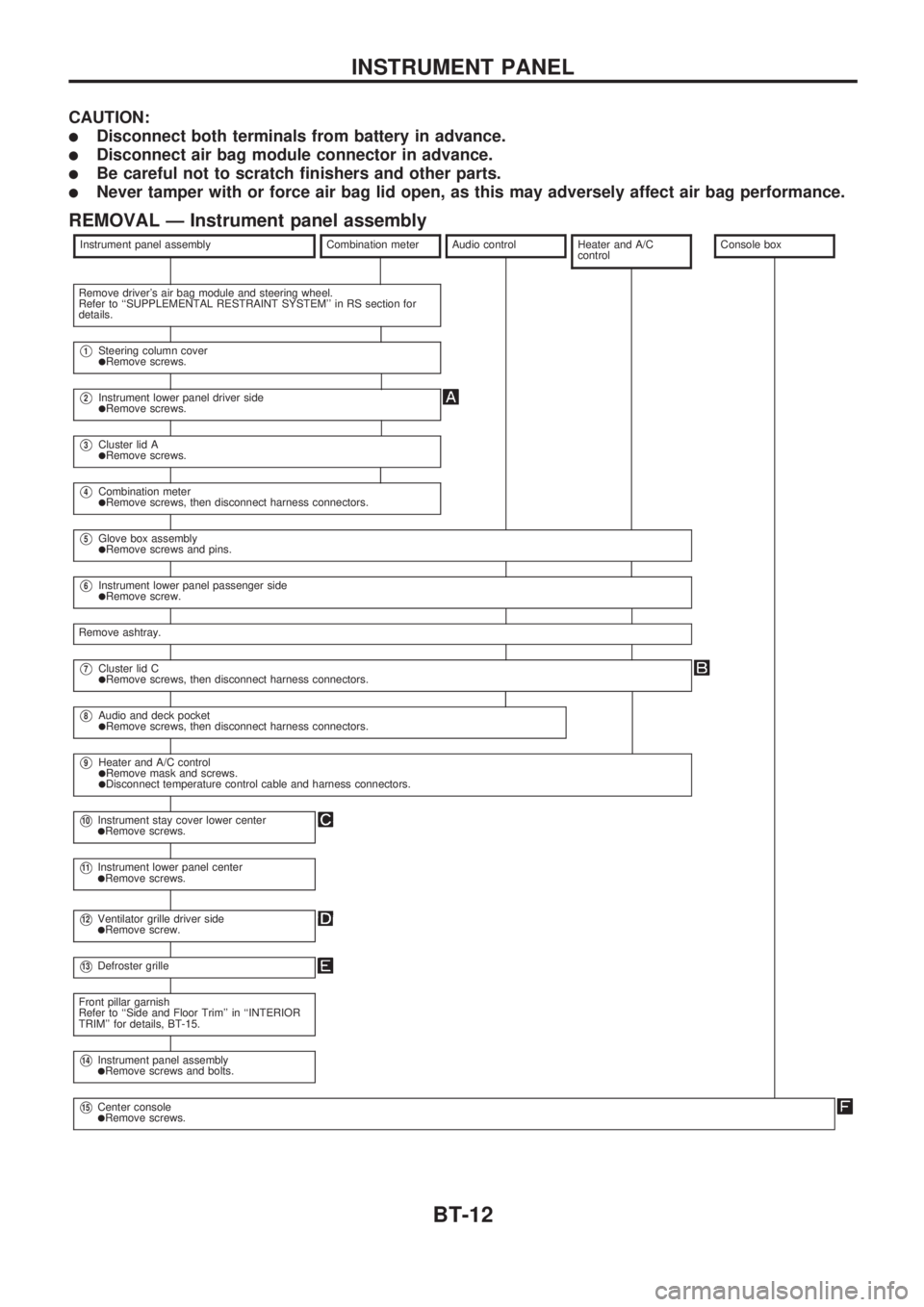
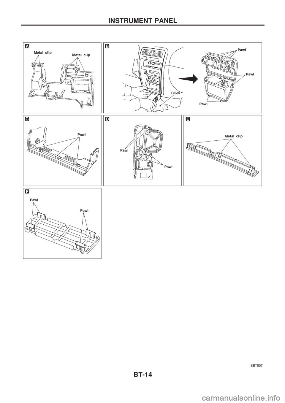
CAUTION:
lDisconnect both terminals from battery in advance.
lDisconnect air bag module connector in advance.
lBe careful not to scratch finishers and other parts.
lNever tamper with or force air bag lid open, as this may adversely affect air bag performance.
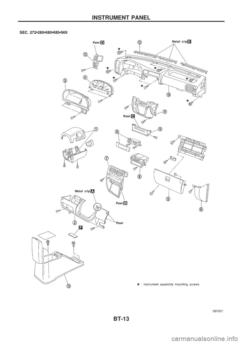
REMOVAL Ð Instrument panel assembly
Instrument panel assemblyCombination meterAudio controlHeater and A/C
controlConsole box
Remove driver's air bag module and steering wheel.
Refer to ``SUPPLEMENTAL RESTRAINT SYSTEM'' in RS section for
details.
V1Steering column coverlRemove screws.
V2Instrument lower panel driver sidelRemove screws.
V3Cluster lid AlRemove screws.
V4Combination meterlRemove screws, then disconnect harness connectors.
V5Glove box assemblylRemove screws and pins.
V6Instrument lower panel passenger sidelRemove screw.
Remove ashtray.
V7Cluster lid ClRemove screws, then disconnect harness connectors.
V8Audio and deck pocketlRemove screws, then disconnect harness connectors.
V9Heater and A/C controllRemove mask and screws.lDisconnect temperature control cable and harness connectors.
V10Instrument stay cover lower centerlRemove screws.
V11Instrument lower panel centerlRemove screws.
V12Ventilator grille driver sidelRemove screw.
V13Defroster grille
Front pillar garnish
Refer to ``Side and Floor Trim'' in ``INTERIOR
TRIM'' for details, BT-15.
V14Instrument panel assemblylRemove screws and bolts.
V15Center consolelRemove screws.
INSTRUMENT PANEL
BT-12
Page 113 of 1659
SBT627
INSTRUMENT PANEL
BT-13
Page 114 of 1659
SBT507
INSTRUMENT PANEL
BT-14
Page 115 of 1659
Side and Floor Trim
CAUTION:
Wrap the tip of flat-bladed screwdriver with a cloth when removing metal clips from garnishes.
REMOVAL Ð Body side trim
Double cab model
V1Remove front and rear seats. Refer to ``SEAT'' for details, BT-30, 33.
V2Remove front and rear kicking plates.
V3Remove dash side lower finishers.
V4Remove front and rear body side welts.
V5Remove front pillar garnishes.
V6Remove center pillar garnishes.
V7Remove lock pillar garnishes.
Single cab model
V1Remove front seats. Refer to ``SEAT'' for details, BT-30.
V2Remove kicking plates.
V3Remove dash side lower finishers.
V4Remove body side welts.
V5Remove front pillar garnishes.
King cab model
V1Remove body side rear finishers.
V2Remove front seats and jump seats. Refer to ``SEAT'' for details, BT-30, 34.
V3Remove kicking plates.
V4Remove dash side lower finishers.
V5Remove front pillar garnishes.
V6Remove body side finishers.
V7Remove back panel garnish.
V8Remove rear pillar finishers.
V9Remove back panel finisher.
V10Remove body side welts.
V11Remove instrument stay cover lower center and center console. Refer to ``INSTRUMENT PANEL'' for
details, BT-12.
V12Remove accel stopper.
V13Remove rear floor trim.
V14Remove clips and accel stopper, then remove front floor trim.
INTERIOR TRIM
BT-15
Page 165 of 1659

System Chart
Camshaft position sensorc
ECM
(ECCS
control
module)
Mass air flow sensorc
Engine coolant temperature sensorc
Heated oxygen sensor*c
Ignition switchc
Throttle position sensorc
Neutral position switchc
Vehicle speed sensorc
Air conditioner switchc
Battery voltagec
Power steering oil pressure switchc
Intake air temperature sensorc
*: LHD models
Fuel injection &
mixture ratio controlcInjectors
Distributor ignition systemcPower transistor
Idle air control systemcIACV-AAC valve
IACV-FICD solenoid valve
Swirl control valve controlcSwirl control valve control
solenoid valve
EVAP canister controlcEVAP canister purge control
solenoid valve
Fuel pump controlcFuel pump relay
Heated oxygen sensor moni-
tor & on board diagnostic
systemcMalfunction indicator lamp
(On the instrument panel)
Acceleration cut controlcAir conditioner relay
Heated oxygen sensor
heater control*cHeated oxygen sensor
heater
ENGINE AND EMISSION CONTROL OVERALL SYSTEMKA
EC-13