1998 NISSAN PICK-UP instrument panel
[x] Cancel search: instrument panelPage 614 of 1659
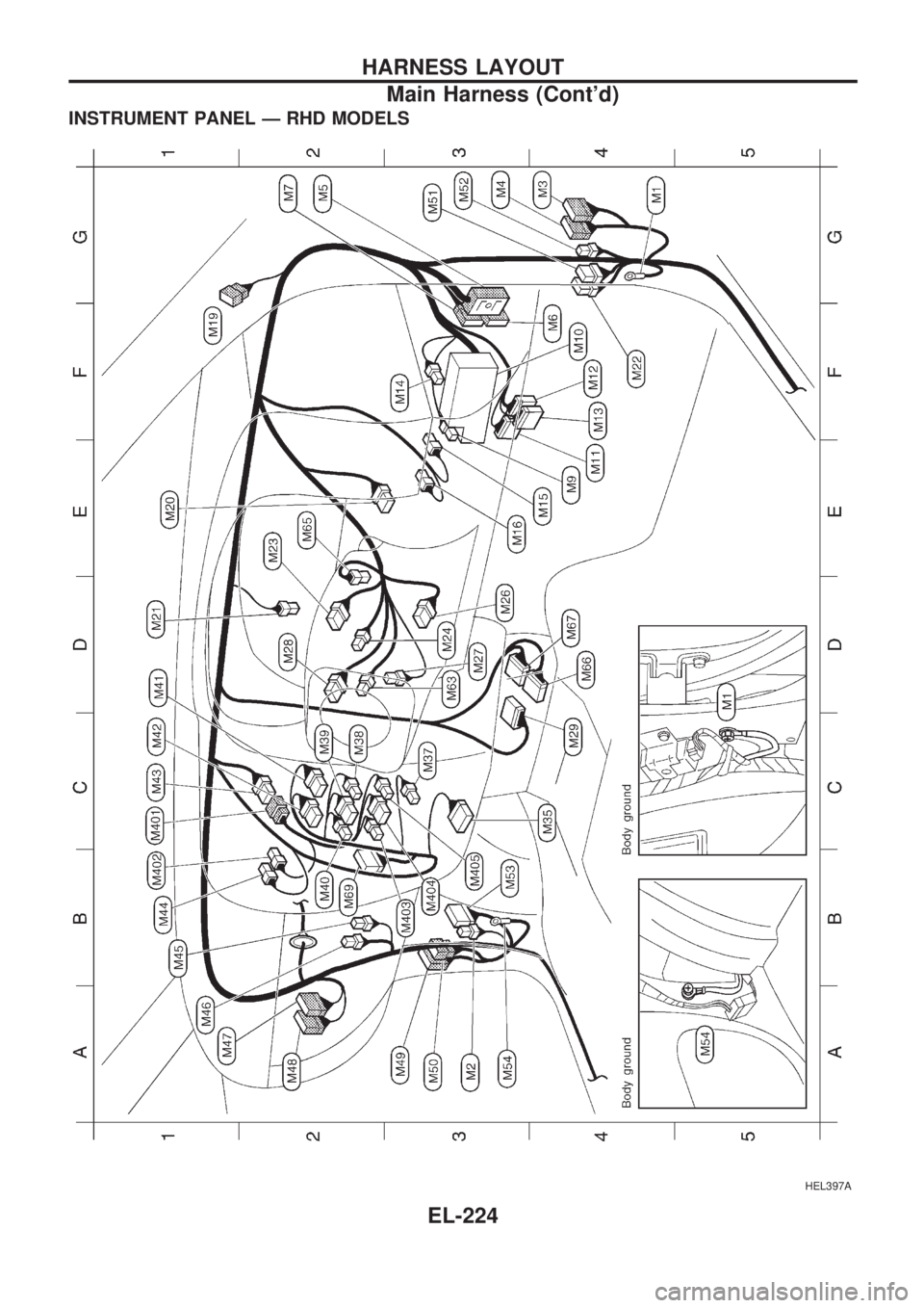
INSTRUMENT PANEL Ð RHD MODELS
HEL397A
HARNESS LAYOUT
Main Harness (Cont'd)
EL-224
Page 806 of 1659
Precautions for NATS
NATS (Nissan Anti-Theft System)
NATS will immobilize the engine if someone tries to start it with-
out the registered key of NATS.
All of the originally supplied ignition key IDs have been NATS
registered.
The NATS security indicator is located on the instrument panel.
The indicator blinks when the ignition switch is in ``OFF'' or
``ACC'' position. Therefore, NATS warns outsiders that the
vehicle is equipped with the anti-theft system.
lGasoline engine:
When NATS detects trouble, the malfunction indicator lamp
(MIL) blinks.
This blinking indicates that the anti-theft is not functioning, so
prompt service is required.
lDiesel engine:
When NATS detects trouble while engine is running or igni-
tion switch in ``ON'' position, the NATS security indicator
comes on.
This indicates that the anti-theft is not functioning, so prompt
service is required.
lWhen servicing NATS (trouble diagnoses, system initialisa-
tion and additional registration of other NATS ignition key
IDs), CONSULT hardware and CONSULT NATS software is
necessary.
Regarding the procedures of NATS initialisation and NATS
ignition key ID registration, refer to CONSULT operation
manual, NATS.
Therefore, CONSULT NATS software (program card and
operation manual) must be kept strictly confidential to main-
tain the integrity of the anti-theft function.
lWhen servicing NATS (trouble diagnoses, system initialisa-
tion and additional registration of other NATS ignition key
IDs), it may be necessary to re-register original key identifi-
cation. Therefore, be sure to receive all keys from vehicle
owner.
A maximum of four key IDs can be registered into NATS.
General Precautions
lDo not operate the engine for an extended period of time
without proper exhaust ventilation.
Keep the work area well ventilated and free of any inflam-
mable materials. Special care should be taken when han-
dling any inflammable or poisonous materials, such as
gasoline, refrigerant gas, etc. When working in a pit or other
enclosed area, be sure to properly ventilate the area before
working with hazardous materials.
Do not smoke while working on the vehicle.
SGI916
SGI285
PRECAUTIONS
GI-2
Page 827 of 1659
Engine compartment
There are several reasons a vehicle or engine vibration could
cause an electrical complaint. Some of the things to check for
are:
lConnectors not fully seated.
lWiring harness not long enough and is being stressed due
to engine vibrations or rocking.
lWires laying across brackets or moving components.
lLoose, dirty or corroded ground wires.
lWires routed too close to hot components.
To inspect components under the hood, start by verifying the
integrity of ground connections. (Refer to GROUND INSPEC-
TION described later.) First check that the system is properly
grounded. Then check for loose connection bygently shaking
the wiring or components as previously explained. Using the
wiring diagrams inspect the wiring for continuity.
Behind the instrument panel
An improperly routed or improperly clamped harness can
become pinched during accessory installation. Vehicle vibration
can aggravate a harness which is routed along a bracket or near
a screw.
Under seating areas
An unclamped or loose harness can cause wiring to be pinched
by seat components (such as slide guides) during vehicle vibra-
tion. If the wiring runs under seating areas, inspect wire routing
for possible damage or pinching.
HEAT SENSITIVE
The owner's problem may occur during hot weather or after car
has sat for a short time. In such cases you will want to check for
a heat sensitive condition.
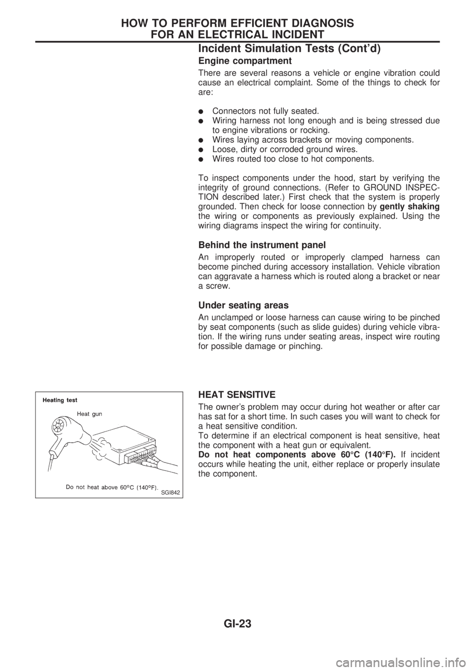
To determine if an electrical component is heat sensitive, heat
the component with a heat gun or equivalent.
Do not heat components above 60ÉC (140ÉF).If incident
occurs while heating the unit, either replace or properly insulate
the component.
SGI842
HOW TO PERFORM EFFICIENT DIAGNOSIS
FOR AN ELECTRICAL INCIDENT
Incident Simulation Tests (Cont'd)
GI-23
Page 864 of 1659
A
A/C HFC134a (R134a) system precaution .....HA-2
A/C HFC134a (R134a) system service
procedure ................................................. HA-48
A/C HFC134a (R134a) system service
tools............................................................ HA-8
A/C HFC134a system service
equipment precaution .............................. HA-10
A/C air flow .................................................. HA-14
A/C component layout ................................. HA-13
A/C compressor clutch removal and
installation ................................................ HA-60
A/C compressor precaution ........................... HA-6
A/C compressor special service tool ............. HA-6
A/C control linkage adjustment
(manual A/C) ............................................ HA-45
A/C control operation (manual A/C) ............ HA-16
A/C diagnostic work flow
(manual A/C) ............................................ HA-17
A/C lubricant (R134a) .................................. HA-50
A/C operational check ................................. HA-18
A/C performance chart ................................ HA-26
A/C performance test diagnoses ................. HA-24
A/C relay ...................................................... HA-44
A/C switch.............................................. HA-16, 43
A/C symptom chart (manual A/C) ............... HA-20
A/C trouble diagnoses (manual A/C)........... HA-17
AAC/V - Wiring diagram ............................ EC-133
ABS (anti-lock brake system) ...................... BR-32
ABS - Wiring diagram .................................. BR-42
Accelerator control system............................. FE-1
Accelerator wire adjustment........................... FE-2
Air bag disposal ........................................... RS-14
Air bag precautions ......................................... GI-1
Air bag ........................................................... RS-6
Air bleeding (hydraulic clutch)........................ CL-5
Air bleeding for brake system........................ BR-4
Air cleaner filter replacement
(KA24 engine).......................................... MA-19
Air cleaner filter replacement
(TD25 engine).......................................... MA-29
Air conditioner cut control ............................ EC-18
Air flow meter - See Mass air flow
sensor ...................................................... EC-89
Alternator ...................................................... EL-41
Angular tightening application ....................... EM-1
Antenna ...................................................... EL-146
Anti-lock brake system - Wiring
diagram .................................................... BR-42
Audio and A/C control removal and
installation - See Instrument panel .......... BT-12
Auto-lock free-running hub........................... FA-15
Auxiliary air control (AAC) valve................ EC-131
Axle housing (rear) ........................................ RA-5
B
Back window .................................................BT-24Back-up lamp switch (M/T)............................ MT-9
Ball joint front axle ....................................... FA-34
Battery .......................................................... EL-18
Baulk ring (M/T) (FS5R30A)........................ MT-36
Baulk ring (M/T) (FS5W71C)....................... MT-15
Blower motor................................................ HA-43
Blower resistor ............................................. HA-43
Body alignment ............................................ BT-43
Body mounting ............................................. BT-41
Boring/horning cylinder block ...................... EM-41
Brake booster .............................................. BR-15
Brake fluid change ......................................... BR-3
Brake fluid level and line check..................... BR-3
Brake fluid level ........................................... MA-35
Brake hydraulic line ....................................... BR-5
Brake inspection .......................................... MA-36
Brake lines and cables inspection .............. MA-35
Brake lining wear temporary checking ........ MA-37
Brake master cylinder .................................. BR-12
Brake pedal.................................................. BR-10
Bulb specifications...................................... EL-252
Bumper, front ................................................. BT-5
Bumper, rear .................................................. BT-8
C
CHARGE - Wiring diagram ...........................EL-34
CIGAR - Wiring diagram ............................ EL-133
CLOCK - Wiring diagram ........................... EL-134
CMPS - Wiring diagram............................... EC-85
CONSULT for ECCS ................................... EC-45
CONSULT general information ..................... GI-34
Cab body ...................................................... BT-40
Camshaft inspection (KA24 engine) ........... EM-28
Camshaft inspection (TD25 engine) ........... EM-85
Camshaft position sensor (CMPS) .............. EC-82
Canister - See EVAP canister ..................... EC-19
Center bearing assembly
(propeller shaft) ........................................ PD-10
Center bearing disassembly
(propeller shaft) .......................................... PD-9
Center case (Transfer) ................................... TF-8
Charging system .......................................... EL-34
Chassis and body maintenance .................. MA-32
Cigarette lighter .......................................... EL-133
Circuit breaker .............................................. EL-13
Clock........................................................... EL-134
Clutch cover ................................................. CL-13
Clutch disc.................................................... CL-12
Clutch fluid level .......................................... MA-32
Clutch master cylinder ................................... CL-6
Clutch operating cylinder ............................... CL-8
Clutch pedal ................................................... CL-4
Clutch release bearing ................................... CL-9
Clutch release mechanism............................. CL-9
Clutch withdrawal lever .................................. CL-9
Collision diagnosis (2WD models)............... RS-21
Collision diagnosis (4WD models)............... RS-42
ALPHABETICAL INDEX
IDX-2
Page 865 of 1659
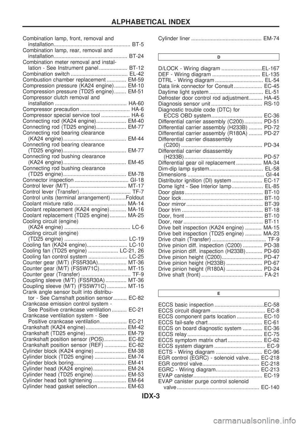
Combination lamp, front, removal and
installation................................................... BT-5
Combination lamp, rear, removal and
installation................................................. BT-24
Combination meter removal and instal-
lation - See Instrument panel ................... BT-12
Combination switch ...................................... EL-42
Combustion chamber replacement ............. EM-59
Compression pressure (KA24 engine) ........ EM-10
Compression pressure (TD25 engine) ........ EM-51
Compressor clutch removal and
installation ................................................ HA-60
Compressor precaution ................................. HA-6
Compressor special service tool ................... HA-6
Connecting rod (KA24 engine).................... EM-40
Connecting rod (TD25 engine).................... EM-77
Connecting rod bearing clearance
(KA24 engine).......................................... EM-44
Connecting rod bearing clearance
(TD25 engine).......................................... EM-77
Connecting rod bushing clearance
(KA24 engine).......................................... EM-45
Connecting rod bushing clearance
(TD25 engine).......................................... EM-78
Connector inspection .................................... GI-18
Control lever (M/T) ...................................... MT-17
Control lever (Transfer) .................................. TF-7
Control units (terminal arrangement) ..........Foldout
Coolant mixture ratio ................................... MA-14
Coolant replacement (KA24 engine) ........... MA-16
Coolant replacement (TD25 engine) ........... MA-25
Cooling circuit (engine)
(KA24 engine) ............................................ LC-6
Cooling circuit (engine)
(TD25 engine) .......................................... LC-19
Cooling fan (KA24 engine)........................... LC-10
Cooling fan (TD25 engine) .................... LC-21, 26
Cooling fan control system .......................... LC-25
Counter gear (M/T) (FS5R30A)................... MT-36
Counter gear (M/T) (FS5W71C).................. MT-15
Counter gear (Transfer) ................................. TF-9
Coupling sleeve (M/T) (FS5R30A) .............. MT-36
Coupling sleeve (M/T) (FS5W71C) ............. MT-15
Crank angle sensor built into distribu-
tor - See Camshaft position sensor ......... EC-82
Crankcase emission control system -
See Positive crankcase ventilation .......... EC-21
Crankcase ventilation system - See
Positive crankcase ventilation.................. EC-21
Crankshaft (KA24 engine) ........................... EM-42
Crankshaft (TD25 engine) ........................... EM-79
Crankshaft position sensor (POS) ............... EC-82
Crankshaft position sensor (REF) ............... EC-82
Cylinder block (KA24 engine) ..................... EM-38
Cylinder block (TD25 engine) ..................... EM-74
Cylinder block boring................................... EM-41
Cylinder head (KA24 engine) ...................... EM-24
Cylinder head (TD25 engine) ...................... EM-53
Cylinder head bolt tightening ...................... EM-64
Cylinder head gasket selection ................... EM-63Cylinder liner ............................................... EM-74
D
D/LOCK - Wiring diagram ...........................EL-167
DEF - Wiring diagram ................................ EL-135
DTRL - Wiring diagram ................................ EL-54
Data link connector for Consult ................... EC-45
Daytime light system .................................... EL-51
Defroster door control rod adjustment......... HA-45
Diagnosis sensor unit .................................. RS-10
Diagnostic trouble code (DTC) for
ECCS OBD system.................................. EC-36
Differential carrier assembly (C200) ............ PD-51
Differential carrier assembly (H233B) ......... PD-72
Differential carrier assembly (R180A) ......... PD-27
Differential carrier disassembly
(C200) ...................................................... PD-34
Differential carrier disassembly
(H233B) .................................................... PD-57
Differential gear oil replacement ................. MA-34
Dim-dip lamp system.................................... EL-58
Dimensions ................................................... GI-44
Distributor ignition (DI) system .................... EC-17
Dome light - See Interior lamp ..................... EL-85
Door glass .................................................... BT-10
Door lock ...................................................... BT-10
Door mirror ................................................... BT-39
Door trim ...................................................... BT-18
Door, front .................................................... BT-10
Door, rear ..................................................... BT-11
Drive belt inspection (KA24 engine) ........... MA-15
Drive belt inspection (TD25 engine) ........... MA-23
Drive chain (Transfer) .................................... TF-9
Drive pinion diff. inspection (C200) ............. PD-38
Drive pinion diff. inspection (H233B) ........... PD-60
Drive pinion height (C200)........................... PD-47
Drive pinion height (H233B) ........................ PD-67
Drive pinion height (R180A) ........................ PD-24
Drive shaft (front) ......................................... FA-21
E
ECCS basic inspection .................................EC-58
ECCS circuit diagram .................................... EC-8
ECCS component parts location ................. EC-10
ECCS fail-safe chart .................................... EC-61
ECCS on board diagnostic system ............. EC-36
ECCS relay .................................................. EC-75
ECCS symptom matrix chart ....................... EC-62
ECCS system diagram .................................. EC-9
ECTS - Wiring diagram ............................... EC-96
EGR control (EGRC) - solenoid valve....... EC-218
EGR control valve...................................... EC-218
EGRC - Wiring diagram............................. EC-213
EVAP canister.............................................. EC-19
EVAP canister purge control solenoid
valve ....................................................... EC-140
ALPHABETICAL INDEX
IDX-3
Page 867 of 1659

HLC - Wiring diagram ................................ EL-130
HORN - Wiring diagram ............................. EL-132
H/SEAT - Wiring diagram........................... EL-152
Harness connector ......................................... EL-2
Harness connector inspection ...................... GI-18
Harness layout ........................................... EL-220
Hazard warning lamp ................................... EL-74
Headlamp ..................................................... EL-44
Headlamp aiming control ............................. EL-63
Headlamp leveler - See Headlamp
aiming control ........................................... EL-63
Headlamp washer ...................................... EL-130
Heated oxygen sensor (HO2S) ................. EC-123
Heated oxygen sensor heater ................... EC-127
Heated oxygen sensor inspection ............... MA-22
Heated seat .................................................. BT-32
Heated seat ................................................ EL-152
Height (Dimensions) ..................................... GI-44
Hood ............................................................... BT-5
Horn ............................................................ EL-132
How to erase DTC for ECCS OBD
system ...................................................... EC-36
I
IACV-AAC valve .................................EC-131, 135
IACV-FICD solenoid valve
(KA24 engine) ........................................ EC-168
IACV-FICD solenoid valve
(TD25 engine) ........................................ EC-231
IATS - Wiring diagram ............................... EC-110
IGN/SG - Wiring diagram .......................... EC-101
ILL - Wiring diagram..................................... EL-81
INJECT - Wiring diagram .......................... EC-144
INT/L - Wiring diagram ................................. EL-85
Identification plate ......................................... GI-42
Idle mixture ratio .......................................... EC-25
Idle speed .................................................... EC-25
Idle speed inspection .................................. MA-30
Ignition coil ................................................. EC-105
Ignition timing............................................... EC-25
Ignition wire inspection ................................ MA-21
Illumination ................................................... EL-81
Injection nozzle inspection .......................... MA-29
Injection nozzle .......................................... EC-186
Injector ............................................... EC-144, 148
Injector removal and installation .................. EC-23
Instrument panel .......................................... BT-12
Intake air temperature sensor ................... EC-109
Intake door control linkage
adjustment................................................ HA-47
Intake manifold .............................................. EM-9
Interior lamp ................................................. EL-85
Interior .......................................................... BT-15
J
Jacking points ................................................GI-47Journal bearing assembly
(propeller shaft) ........................................ PD-11
Journal bearing disassembly
(propeller shaft) ........................................ PD-10
Jump seat..................................................... BT-34
K
Keyless entry system - See Multi-remote
control system .............................................EL-173
Knuckle spindle ............................................ FA-18
L
LSV (Load sensing valve)...............................BR-7
Leaf spring (rear) ......................................... RA-13
Length (Dimensions) ..................................... GI-44
License lamp ................................................ EL-66
Lifting points .................................................. GI-47
Limited slip diff. adjustment (C200) ............. PD-41
Limited slip diff. adjustment (H233B) .......... PD-63
Limited slip diff. assembly (C200) ............... PD-43
Limited slip diff. assembly (H233B) ............. PD-64
Limited slip diff. disassembly (C200)........... PD-39
Limited slip diff. disassembly (H233B) ........ PD-61
Limited slip diff. inspection (C200) .............. PD-40
Limited slip diff. inspection (H233B) ............ PD-62
Liquid gasket application ............................... EM-1
Location of electrical units.......................... EL-217
Lock, door .................................................... BT-10
Lubricant (R134a) A/C ................................. HA-50
Lubricants .................................................... MA-12
Lubrication circuit (engine)
(KA24 engine) ............................................ LC-3
Lubrication circuit (engine)
(TD25 engine) .......................................... LC-12
Lubrication-locks, hinges and hood
latches ..................................................... MA-39
M
M/T major overhaul (FS5R30A) ...................MT-35
M/T major overhaul (FS5W71C) ................. MT-14
M/T removal and installation ....................... MT-11
MAFS - Wiring diagram ............................... EC-91
MAIN - Wiring diagram ................................ EC-76
METER - Wiring diagram ............................. EL-90
MIL & Data link connectors ....................... EC-173
MIRROR - Wiring diagram ......................... EL-150
MULTI - Wiring diagram ............................. EL-175
Main drive gear (M/T) (FS5R30A)............... MT-36
Main drive gear (M/T) (FS5W71C).............. MT-15
Main gear (Transfer) ...................................... TF-9
Mainshaft (M/T) (FS5R30A) ........................ MT-36
Mainshaft (M/T) (FS5W71C) ....................... MT-15
Mainshaft (Transfer) ....................................... TF-9
Maintenance (engine) (KA24 engine) ......... MA-15
ALPHABETICAL INDEX
IDX-5
Page 892 of 1659
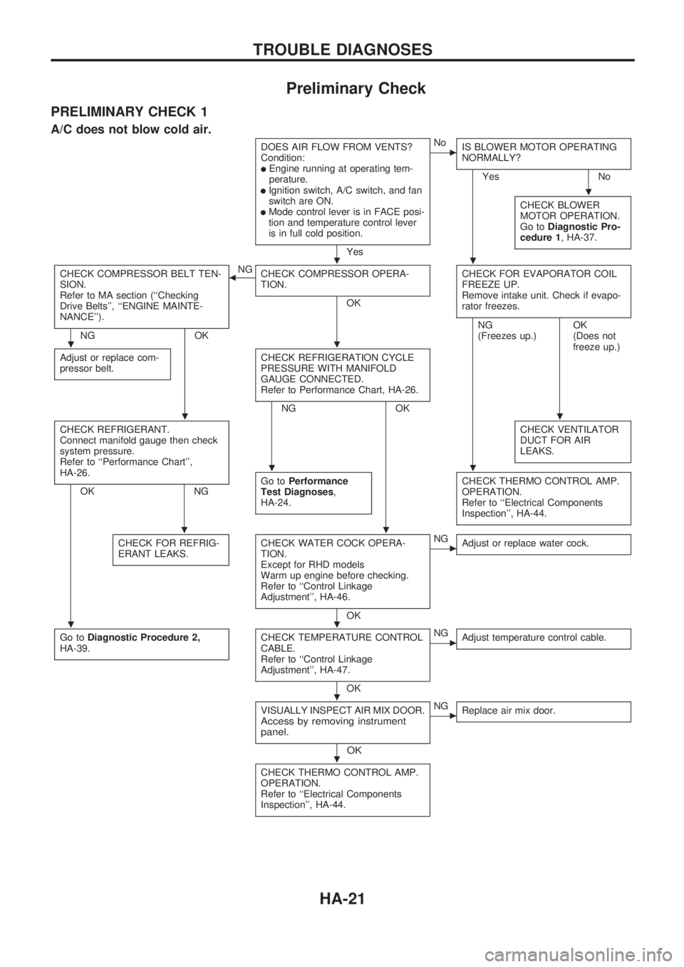
Preliminary Check
PRELIMINARY CHECK 1
A/C does not blow cold air.
DOES AIR FLOW FROM VENTS?
Condition:
lEngine running at operating tem-
perature.
lIgnition switch, A/C switch, and fan
switch are ON.
lMode control lever is in FACE posi-
tion and temperature control lever
is in full cold position.
Yes
cNo
IS BLOWER MOTOR OPERATING
NORMALLY?
Yes No
CHECK BLOWER
MOTOR OPERATION.
Go toDiagnostic Pro-
cedure 1, HA-37.
CHECK COMPRESSOR BELT TEN-
SION.
Refer to MA section (``Checking
Drive Belts'', ``ENGINE MAINTE-
NANCE'').
NG OKNG
bCHECK COMPRESSOR OPERA-
TION.
OKCHECK FOR EVAPORATOR COIL
FREEZE UP.
Remove intake unit. Check if evapo-
rator freezes.
Adjust or replace com-
pressor belt.CHECK REFRIGERATION CYCLE
PRESSURE WITH MANIFOLD
GAUGE CONNECTED.
Refer to Performance Chart, HA-26.
NG OKNG
(Freezes up.)OK
(Does not
freeze up.)
CHECK REFRIGERANT.
Connect manifold gauge then check
system pressure.
Refer to ``Performance Chart'',
HA-26.
OK NGCHECK VENTILATOR
DUCT FOR AIR
LEAKS.Go toPerformance
Test Diagnoses,
HA-24.CHECK THERMO CONTROL AMP.
OPERATION.
Refer to ``Electrical Components
Inspection'', HA-44.
CHECK FOR REFRIG-
ERANT LEAKS.CHECK WATER COCK OPERA-
TION.
Except for RHD models
Warm up engine before checking.
Refer to ``Control Linkage
Adjustment'', HA-46.
OK
cNG
Adjust or replace water cock.
Go toDiagnostic Procedure 2,
HA-39.CHECK TEMPERATURE CONTROL
CABLE.
Refer to ``Control Linkage
Adjustment'', HA-47.
OK
cNG
Adjust temperature control cable.
VISUALLY INSPECT AIR MIX DOOR.Access by removing instrument
panel.
OK
cNG
Replace air mix door.
CHECK THERMO CONTROL AMP.
OPERATION.
Refer to ``Electrical Components
Inspection'', HA-44.
.
..
..
..
..
..
..
.
.
TROUBLE DIAGNOSES
HA-21
Page 894 of 1659
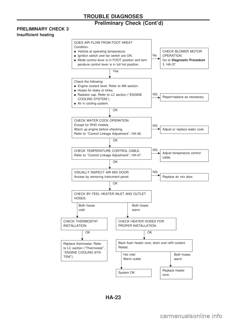
PRELIMINARY CHECK 3
Insufficient heating
DOES AIR FLOW FROM FOOT AREA?
Condition:
lVehicle at operating temperature.
lIgnition switch and fan switch are ON.
lMode control lever is in FOOT position and tem-
perature control lever is in full hot position.
Yes
cNoCHECK BLOWER MOTOR
OPERATION.
Go toDiagnostic Procedure
1, HA-37.
Check the following:
lEngine coolant level. Refer to MA section.
lHoses for leaks or kinks.
lRadiator cap. Refer to LC section (``ENGINE
COOLING SYSTEM'').
lAir in cooling system.
OK
cNG
Repair/replace as necessary.
CHECK WATER COCK OPERATION.
Except for RHD models
Warm up engine before checking.
Refer to ``Control Linkage Adjustment'', HA-46.
OK
cNG
Adjust or replace water cock.
CHECK TEMPERATURE CONTROL CABLE.
Refer to ``Control Linkage Adjustment'', HA-47.
OK
cNG
Adjust temperature control
cable.
VISUALLY INSPECT AIR MIX DOOR.
Access by removing instrument panel.
OK
cNG
Replace air mix door.
CHECK BY FEEL HEATER INLET AND OUTLET
HOSES.
Both hoses
coldBoth hoses
warm
CHECK THERMOSTAT
INSTALLATION.
OKCHECK HEATER HOSES FOR
PROPER INSTALLATION.OK
Replace thermostat. Refer
to LC section (``Thermostat'',
``ENGINE COOLING SYS-
TEM'').
Back flush heater core, drain and refill coolant.
Retest.
Hot inlet
Warm outletBoth hoses
warm
System OK
Replace heater
core.
.
.
.
.
.
..
..
..
TROUBLE DIAGNOSES
Preliminary Check (Cont'd)
HA-23