Page 976 of 1659

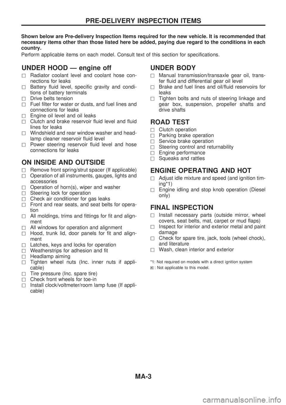
Shown below are Pre-delivery Inspection Items required for the new vehicle. It is recommended that
necessary items other than those listed here be added, paying due regard to the conditions in each
country.
Perform applicable items on each model. Consult text of this section for specifications.
UNDER HOOD Ð engine off
hRadiator coolant level and coolant hose con-
nections for leaks
hBattery fluid level, specific gravity and condi-
tions of battery terminals
hDrive belts tension
hFuel filter for water or dusts, and fuel lines and
connections for leaks
hEngine oil level and oil leaks
hClutch and brake reservoir fluid level and fluid
lines for leaks
hWindshield and rear window washer and head-
lamp cleaner reservoir fluid level
hPower steering reservoir fluid level and hose
connections for leaks
ON INSIDE AND OUTSIDE
hRemove front spring/strut spacer (If applicable)
hOperation of all instruments, gauges, lights and
accessories
hOperation of horn(s), wiper and washer
hSteering lock for operation
hCheck air conditioner for gas leaks
hFront and rear seats, and seat belts for opera-
tion
hAll moldings, trims and fittings for fit and align-
ment
hAll windows for operation and alignment
hHood, trunk lid, door panels for fit and align-
ment
hLatches, keys and locks for operation
hWeatherstrips for adhesion and fit
hHeadlamp aiming
hTighten wheel nuts (Inc. inner nuts if appli-
cable)
hTire pressure (Inc. spare tire)
hCheck front wheels for toe-in
hInstall clock/voltmeter/room lamp fuse (If appli-
cable)
UNDER BODY
hManual transmission/transaxle gear oil, trans-
fer fluid and differential gear oil level
hBrake and fuel lines and oil/fluid reservoirs for
leaks
hTighten bolts and nuts of steering linkage and
gear box, suspension, propeller shafts and
drive shafts
ROAD TEST
hClutch operation
hParking brake operation
hService brake operation
hSteering control and returnability
hEngine performance
hSqueaks and rattles
ENGINE OPERATING AND HOT
hAdjust idle mixture and speed (and ignition tim-
ing*1)
hEngine idling and stop knob operation (Diesel
only)
FINAL INSPECTION
hInstall necessary parts (outside mirror, wheel
covers, seat belts, mat, carpet or mud flaps)
hInspect for interior and exterior metal and paint
damage
hCheck for spare tire, jack, tools (wheel chock),
and literature
hWash, clean interior and exterior
*1: Not required on models with a direct ignition system
h
X: Not applicable to this model.
PRE-DELIVERY INSPECTION ITEMS
MA-3
Page 1173 of 1659

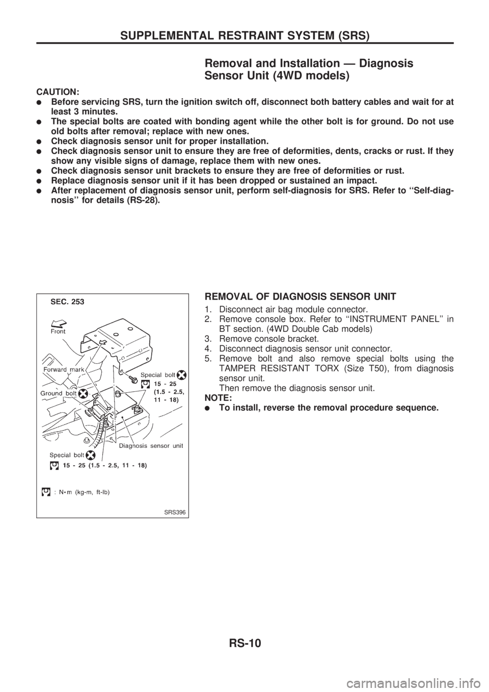
Removal and Installation Ð Diagnosis
Sensor Unit (4WD models)
CAUTION:
lBefore servicing SRS, turn the ignition switch off, disconnect both battery cables and wait for at
least 3 minutes.
lThe special bolts are coated with bonding agent while the other bolt is for ground. Do not use
old bolts after removal; replace with new ones.
lCheck diagnosis sensor unit for proper installation.
lCheck diagnosis sensor unit to ensure they are free of deformities, dents, cracks or rust. If they
show any visible signs of damage, replace them with new ones.
lCheck diagnosis sensor unit brackets to ensure they are free of deformities or rust.
lReplace diagnosis sensor unit if it has been dropped or sustained an impact.
lAfter replacement of diagnosis sensor unit, perform self-diagnosis for SRS. Refer to ``Self-diag-
nosis'' for details (RS-28).
REMOVAL OF DIAGNOSIS SENSOR UNIT
1. Disconnect air bag module connector.
2. Remove console box. Refer to ``INSTRUMENT PANEL'' in
BT section. (4WD Double Cab models)
3. Remove console bracket.
4. Disconnect diagnosis sensor unit connector.
5. Remove bolt and also remove special bolts using the
TAMPER RESISTANT TORX (Size T50), from diagnosis
sensor unit.
Then remove the diagnosis sensor unit.
NOTE:
lTo install, reverse the removal procedure sequence.
SRS396
SUPPLEMENTAL RESTRAINT SYSTEM (SRS)
RS-10
Page 1232 of 1659
![NISSAN PICK-UP 1998 Repair Manual 3. Remove steering wheel using Tool.
lFor installation, refer to RS section [``Air Bag Module and
Spiral Cable, ``SUPPLEMENTAL RESTRAINT SYSTEM
(SRS)].
Steering Column
REMOVAL
CAUTION:
lThe rotati NISSAN PICK-UP 1998 Repair Manual 3. Remove steering wheel using Tool.
lFor installation, refer to RS section [``Air Bag Module and
Spiral Cable, ``SUPPLEMENTAL RESTRAINT SYSTEM
(SRS)].
Steering Column
REMOVAL
CAUTION:
lThe rotati](/manual-img/5/57374/w960_57374-1231.png)
3. Remove steering wheel using Tool.
lFor installation, refer to RS section [``Air Bag Module and
Spiral Cable'', ``SUPPLEMENTAL RESTRAINT SYSTEM
(SRS)''].
Steering Column
REMOVAL
CAUTION:
lThe rotation of the spiral cable (SRS ``Air bag'' compo-
nent part) is limited. If the steering gear must be
removed, set the front wheels in the straight-ahead
direction.
Do not rotate the steering column while the steering gear
is removed.
lRemove the steering wheel before removing the steering
lower joint to avoid damaging the SRS spiral cable. Refer
to ST-9.
1. Remove steering wheel, refer to ST-9.
2. Remove steering column cover.
3. Remove instrument lower panel.
4. Disconnect combination switch electrical connectors and air
bag harness connector.
5. Remove dash insulator.
6. Remove bolt from lower joint.
7. Remove two steering column bolts and remove steering col-
umn.
INSTALLATION
lWhen installing steering column, finger-tighten all lower
bracket and clamp retaining bolts; then tighten them
securely. Make sure that undue stress is not applied to steer-
ing column.
lWhen fitting steering lower joint, be sure tightening bolt faces
cutout portion.
lAlign spiral cable correctly when installing steering wheel.
Refer to RS section [``Air Bag Module and Spiral Cable'',
``SUPPLEMENTAL RESTRAINT SYSTEM (SRS)''].
CAUTION:
After installation, turn steering wheel to make sure it moves
smoothly. Ensure the number of turns from the straight for-
ward position to left and right locks are the same. Be sure
that the steering wheel is in a neutral position when driving
straight ahead.
SST515B
SST666A
STEERING WHEEL AND STEERING COLUMN
Steering Wheel (Cont'd)
ST-10
Page 1519 of 1659
How to Read Harness Layout
Example:
G2E1B/6: ASCD ACTUATOR
Connector color / Cavity
Connector number
Grid reference
The following Harness Layouts use a map style grid to help locate connectors on the drawings:
lMain Harness (Instrument Panel, Engine Compartment)
lEngine Room Harness
lEngine Control Harness
To use the grid reference
1) Find the desired connector number on the connector list.
2) Find the grid reference.
3) On the drawing, find the crossing of the grid reference letter column and number row.
4) Find the connector number in the crossing zone.
5) Follow the line (if used) to the connector.
CONNECTOR SYMBOL
Main symbols of connector (in Harness Layout) are indicated in the below.
Connector typeWater proof type Standard type
Male Female Male Female
lCavity: Less than 4
lRelay connector
lCavity: From 5 to 8
lCavity: More than 9
lGround terminal etc.
Ð
HARNESS LAYOUT
EL-221
Page 1520 of 1659
Main Harness
INSTRUMENT PANEL Ð LHD MODELS FOR EUROPE
HEL395A
HARNESS LAYOUT
EL-222
Page 1522 of 1659
INSTRUMENT PANEL Ð RHD MODELS
HEL397A
HARNESS LAYOUT
Main Harness (Cont'd)
EL-224