1998 NISSAN PICK-UP instrument panel
[x] Cancel search: instrument panelPage 188 of 1659
Introduction
The ECM (ECCS control module) has an on board diagnostic system, which detects malfunctions related to
engine sensors or actuators. Self-diagnosis items are listed in ``DIAGNOSTIC TROUBLE CODE INDEX'',
EC-1.
The malfunction indicator lamp (MIL) on the instrument panel lights up when a malfunction is detected, or
when the ECM enters fail-safe mode (Refer to EC-61).
Diagnostic Trouble Code (DTC)
HOW TO CONFIRM MALFUNCTION ITEMS
Malfunction items can be confirmed by the following methods.
1. The number of blinks of the malfunction indicator lamp in the Diagnostic Test Mode II (Self- Diag-
nostic Results) indicates the DTC. Examples: 11, 21 etc.
2. CONSULT displays the malfunctioning component or system in ``SELF DIAGNOSTIC RESULTS''
mode.
lOutput of a DTC indicates a malfunction. However, Mode II does not indicate whether the mal-
function is still occurring or has occurred in the past and has returned to normal.
CONSULT can identify malfunction status as shown below. Therefore, using CONSULT (if avail-
able) is recommended.
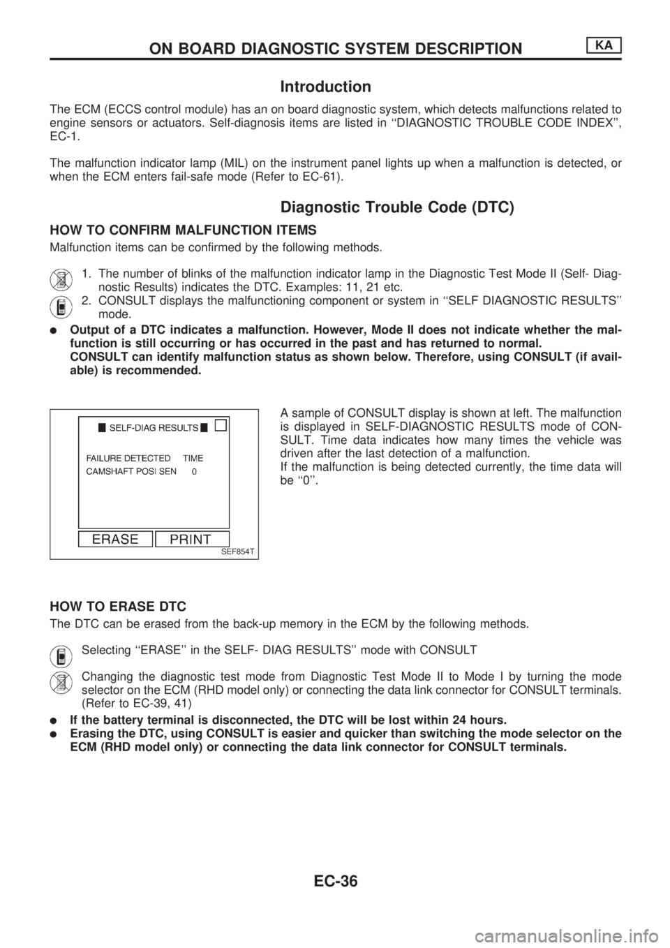
A sample of CONSULT display is shown at left. The malfunction
is displayed in SELF-DIAGNOSTIC RESULTS mode of CON-
SULT. Time data indicates how many times the vehicle was
driven after the last detection of a malfunction.
If the malfunction is being detected currently, the time data will
be ``0''.
HOW TO ERASE DTC
The DTC can be erased from the back-up memory in the ECM by the following methods.
Selecting ``ERASE'' in the SELF- DIAG RESULTS'' mode with CONSULT
Changing the diagnostic test mode from Diagnostic Test Mode II to Mode I by turning the mode
selector on the ECM (RHD model only) or connecting the data link connector for CONSULT terminals.
(Refer to EC-39, 41)
lIf the battery terminal is disconnected, the DTC will be lost within 24 hours.
lErasing the DTC, using CONSULT is easier and quicker than switching the mode selector on the
ECM (RHD model only) or connecting the data link connector for CONSULT terminals.
SEF854T
ON BOARD DIAGNOSTIC SYSTEM DESCRIPTIONKA
EC-36
Page 190 of 1659
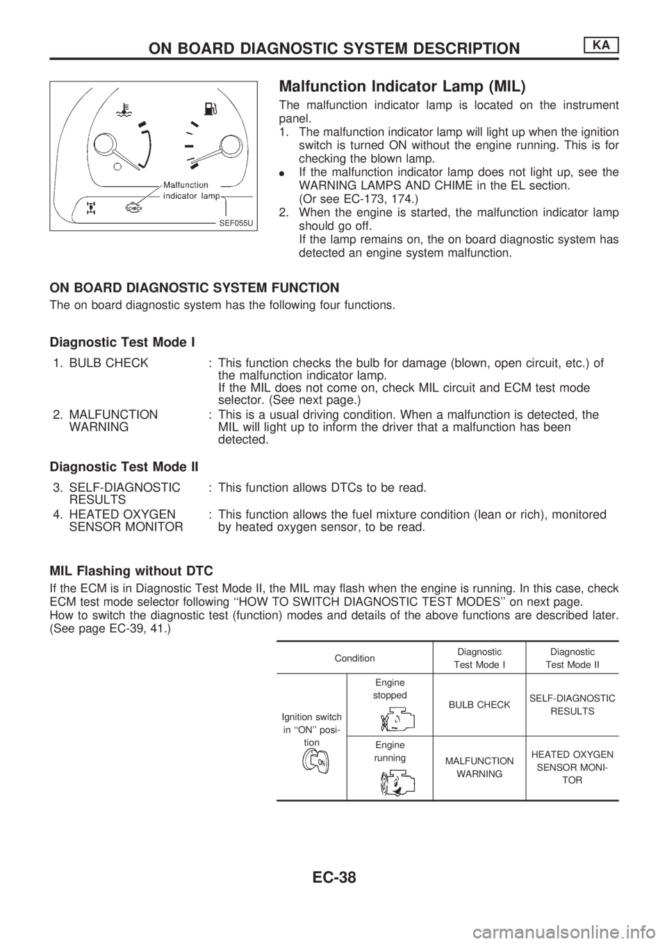
Malfunction Indicator Lamp (MIL)
The malfunction indicator lamp is located on the instrument
panel.
1. The malfunction indicator lamp will light up when the ignition
switch is turned ON without the engine running. This is for
checking the blown lamp.
lIf the malfunction indicator lamp does not light up, see the
WARNING LAMPS AND CHIME in the EL section.
(Or see EC-173, 174.)
2. When the engine is started, the malfunction indicator lamp
should go off.
If the lamp remains on, the on board diagnostic system has
detected an engine system malfunction.
ON BOARD DIAGNOSTIC SYSTEM FUNCTION
The on board diagnostic system has the following four functions.
Diagnostic Test Mode I
1. BULB CHECK : This function checks the bulb for damage (blown, open circuit, etc.) of
the malfunction indicator lamp.
If the MIL does not come on, check MIL circuit and ECM test mode
selector. (See next page.)
2. MALFUNCTION
WARNING: This is a usual driving condition. When a malfunction is detected, the
MIL will light up to inform the driver that a malfunction has been
detected.
Diagnostic Test Mode II
3. SELF-DIAGNOSTIC
RESULTS: This function allows DTCs to be read.
4. HEATED OXYGEN
SENSOR MONITOR: This function allows the fuel mixture condition (lean or rich), monitored
by heated oxygen sensor, to be read.
MIL Flashing without DTC
If the ECM is in Diagnostic Test Mode II, the MIL may flash when the engine is running. In this case, check
ECM test mode selector following ``HOW TO SWITCH DIAGNOSTIC TEST MODES'' on next page.
How to switch the diagnostic test (function) modes and details of the above functions are described later.
(See page EC-39, 41.)
ConditionDiagnostic
Test Mode IDiagnostic
Test Mode II
Ignition switch
in ``ON'' posi-
tion
Engine
stopped
BULB CHECKSELF-DIAGNOSTIC
RESULTS
Engine
running
MALFUNCTION
WARNINGHEATED OXYGEN
SENSOR MONI-
TOR
SEF055U
ON BOARD DIAGNOSTIC SYSTEM DESCRIPTIONKA
EC-38
Page 195 of 1659
DIAGNOSTIC TEST MODE IÐBULB CHECK
In this mode, the MALFUNCTION INDICATOR LAMP on the instrument panel should stay ON. If it remains
OFF, check the bulb. (See the WARNING LAMPS AND CHIME in the EL section. Or see EC-173, 174.)
DIAGNOSTIC TEST MODE IÐMALFUNCTION WARNING
MALFUNCTION
INDICATOR LAMPCondition
ON When the malfunction is detected (Refer to EC-1.) or the ECM's CPU is malfunctioning.
OFF No malfunction
lThese Diagnostic Trouble Code Numbers are clarified in Diagnostic Test Mode II (SELF-DIAGNOSTIC
RESULTS).
DIAGNOSTIC TEST MODE IIÐSELF-DIAGNOSTIC RESULTS
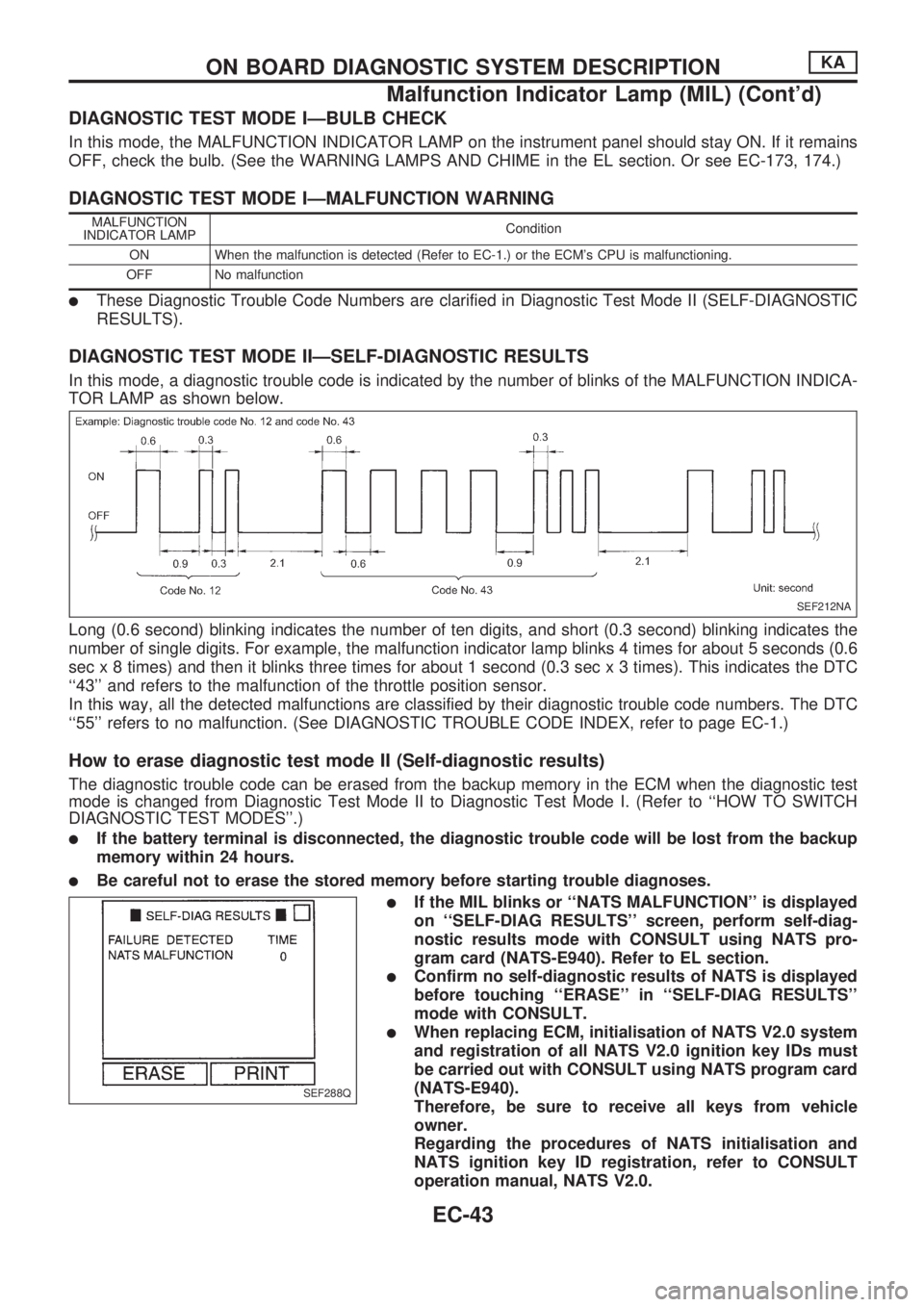
In this mode, a diagnostic trouble code is indicated by the number of blinks of the MALFUNCTION INDICA-
TOR LAMP as shown below.
Long (0.6 second) blinking indicates the number of ten digits, and short (0.3 second) blinking indicates the
number of single digits. For example, the malfunction indicator lamp blinks 4 times for about 5 seconds (0.6
sec x 8 times) and then it blinks three times for about 1 second (0.3 sec x 3 times). This indicates the DTC
``43'' and refers to the malfunction of the throttle position sensor.
In this way, all the detected malfunctions are classified by their diagnostic trouble code numbers. The DTC
``55'' refers to no malfunction. (See DIAGNOSTIC TROUBLE CODE INDEX, refer to page EC-1.)
How to erase diagnostic test mode II (Self-diagnostic results)
The diagnostic trouble code can be erased from the backup memory in the ECM when the diagnostic test
mode is changed from Diagnostic Test Mode II to Diagnostic Test Mode I. (Refer to ``HOW TO SWITCH
DIAGNOSTIC TEST MODES''.)
lIf the battery terminal is disconnected, the diagnostic trouble code will be lost from the backup
memory within 24 hours.
lBe careful not to erase the stored memory before starting trouble diagnoses.
lIf the MIL blinks or ``NATS MALFUNCTION'' is displayed
on ``SELF-DIAG RESULTS'' screen, perform self-diag-
nostic results mode with CONSULT using NATS pro-
gram card (NATS-E940). Refer to EL section.
lConfirm no self-diagnostic results of NATS is displayed
before touching ``ERASE'' in ``SELF-DIAG RESULTS''
mode with CONSULT.
lWhen replacing ECM, initialisation of NATS V2.0 system
and registration of all NATS V2.0 ignition key IDs must
be carried out with CONSULT using NATS program card
(NATS-E940).
Therefore, be sure to receive all keys from vehicle
owner.
Regarding the procedures of NATS initialisation and
NATS ignition key ID registration, refer to CONSULT
operation manual, NATS V2.0.
SEF212NA
SEF288Q
ON BOARD DIAGNOSTIC SYSTEM DESCRIPTIONKA
Malfunction Indicator Lamp (MIL) (Cont'd)
EC-43
Page 213 of 1659
Fail-Safe Chart
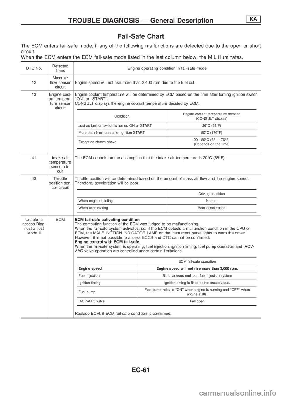
The ECM enters fail-safe mode, if any of the following malfunctions are detected due to the open or short
circuit.
When the ECM enters the ECM fail-safe mode listed in the last column below, the MIL illuminates.
DTC No.Detected
itemsEngine operating condition in fail-safe mode
12Mass air
flow sensor
circuitEngine speed will not rise more than 2,400 rpm due to the fuel cut.
13 Engine cool-
ant tempera-
ture sensor
circuitEngine coolant temperature will be determined by ECM based on the time after turning ignition switch
``ON'' or ``START''.
CONSULT displays the engine coolant temperature decided by ECM.
41 Intake air
temperature
sensor cir-
cuitThe ECM controls on the assumption that the intake air temperature is 20ÉC (68ÉF).
43 Throttle
position sen-
sor circuitThrottle position will be determined based on the amount of mass air flow and the engine speed.
Therefore, acceleration will be poor.
Unable to
access Diag-
nostic Test
Mode IIECMECM fail-safe activating condition
The computing function of the ECM was judged to be malfunctioning.
When the fail-safe system activates, i.e. if the ECM detects a malfunction condition in the CPU of
ECM, the MALFUNCTION INDICATOR LAMP on the instrument panel lights to warn the driver.
However, it is not possible to access ECCS and DTC cannot be confirmed.
Engine control with ECM fail-safe
When the fail-safe system is operating, fuel injection, ignition timing, fuel pump operation and IACV-
AAC valve operation are controlled under certain limitations.
Replace ECM, if ECM fail-safe condition is confirmed.
ConditionEngine coolant temperature decided
(CONSULT display)
Just as ignition switch is turned ON or START 20ÉC (68ÉF)
More than 6 minutes after ignition START 80ÉC (176ÉF)
Except as shown above20 - 80ÉC (68 - 176ÉF)
(Depends on the time)
Driving condition
When engine is idling Normal
When accelerating Poor acceleration
ECM fail-safe operation
Engine speed Engine speed will not rise more than 3,000 rpm.
Fuel injection Simultaneous multiport fuel injection system
Ignition timing Ignition timing is fixed at the preset value.
Fuel pumpFuel pump relay is ``ON'' when engine is running and ``OFF'' when
engine stalls.
IACV-AAC valve Full open
TROUBLE DIAGNOSIS Ð General DescriptionKA
EC-61
Page 220 of 1659
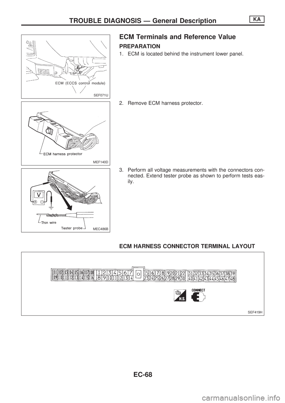
ECM Terminals and Reference Value
PREPARATION
1. ECM is located behind the instrument lower panel.
2. Remove ECM harness protector.
3. Perform all voltage measurements with the connectors con-
nected. Extend tester probe as shown to perform tests eas-
ily.
ECM HARNESS CONNECTOR TERMINAL LAYOUT
SEF071U
MEF140D
MEC486B
SEF419H
TROUBLE DIAGNOSIS Ð General DescriptionKA
EC-68
Page 277 of 1659
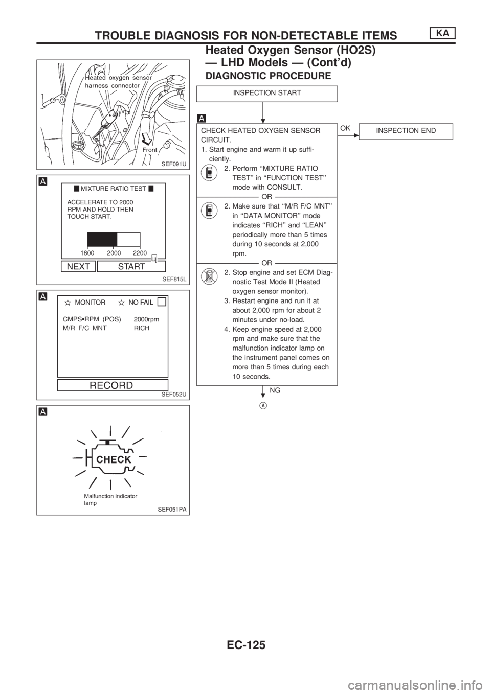
DIAGNOSTIC PROCEDURE
INSPECTION START
CHECK HEATED OXYGEN SENSOR
CIRCUIT.
1. Start engine and warm it up suffi-
ciently.
2. Perform ``MIXTURE RATIO
TEST'' in ``FUNCTION TEST''
mode with CONSULT.
----------------------------------------------------------------------------------------------------------------------------------OR----------------------------------------------------------------------------------------------------------------------------------
2. Make sure that ``M/R F/C MNT''
in ``DATA MONITOR'' mode
indicates ``RICH'' and ``LEAN''
periodically more than 5 times
during 10 seconds at 2,000
rpm.
----------------------------------------------------------------------------------------------------------------------------------OR----------------------------------------------------------------------------------------------------------------------------------
2. Stop engine and set ECM Diag-
nostic Test Mode II (Heated
oxygen sensor monitor).
3. Restart engine and run it at
about 2,000 rpm for about 2
minutes under no-load.
4. Keep engine speed at 2,000
rpm and make sure that the
malfunction indicator lamp on
the instrument panel comes on
more than 5 times during each
10 seconds.
NG
cOK
INSPECTION END
VA
SEF091U
SEF815L
SEF052U
SEF051PA
.
.
TROUBLE DIAGNOSIS FOR NON-DETECTABLE ITEMSKA
Heated Oxygen Sensor (HO2S)
Ð LHD Models Ð (Cont'd)
EC-125
Page 611 of 1659
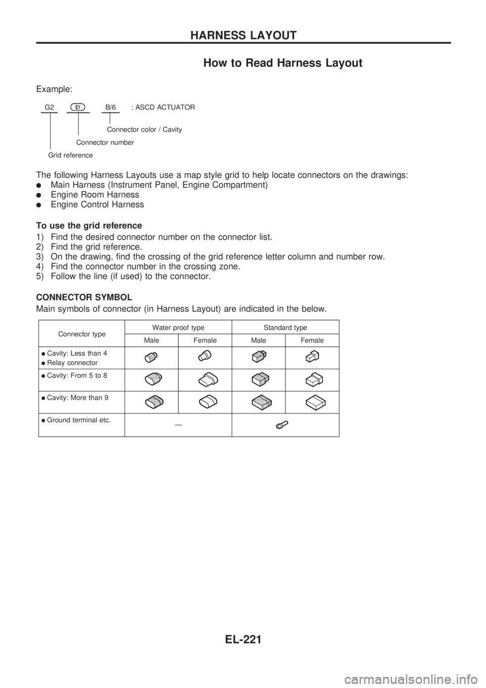
How to Read Harness Layout
Example:
G2E1B/6: ASCD ACTUATOR
Connector color / Cavity
Connector number
Grid reference
The following Harness Layouts use a map style grid to help locate connectors on the drawings:
lMain Harness (Instrument Panel, Engine Compartment)
lEngine Room Harness
lEngine Control Harness
To use the grid reference
1) Find the desired connector number on the connector list.
2) Find the grid reference.
3) On the drawing, find the crossing of the grid reference letter column and number row.
4) Find the connector number in the crossing zone.
5) Follow the line (if used) to the connector.
CONNECTOR SYMBOL
Main symbols of connector (in Harness Layout) are indicated in the below.
Connector typeWater proof type Standard type
Male Female Male Female
lCavity: Less than 4
lRelay connector
lCavity: From 5 to 8
lCavity: More than 9
lGround terminal etc.
Ð
HARNESS LAYOUT
EL-221
Page 612 of 1659
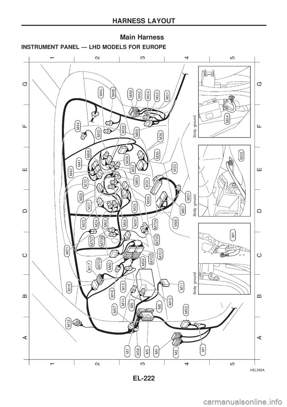
Main Harness
INSTRUMENT PANEL Ð LHD MODELS FOR EUROPE
HEL395A
HARNESS LAYOUT
EL-222