1998 NISSAN PICK-UP charging
[x] Cancel search: chargingPage 214 of 1659

Symptom Matrix Chart
SYMPTOM
Reference page
HARD/NO START/RESTART (EXCP. HA)
ENGINE STALL
HESITATION/SURGING/FLAT SPOT
SPARK KNOCK/DETONATION
LACK OF POWER/POOR ACCELERATION
HIGH IDLE/LOW IDLE
ROUGH IDLE/HUNTING
IDLING VIBRATION
SLOW/NO RETURN TO IDLE
OVERHEATS/WATER TEMPERATURE HIGH
EXCESSIVE FUEL CONSUMPTION
EXCESSIVE OIL CONSUMPTION
BATTERY DEAD (UNDER CHARGE)
OVERCOOLS
OVERCHARGING
Warranty Symptom Code AA AB AC AD AE AF AG AH AJ AK AL AM HA 1P 1X
Basic engine control system
Fuel Fuel pump circuitllljlljjjEC-151
Fuel pressure regulator system
llljljlljlEC-22
Injector circuit
llljlll lEC-144
Evaporative emission systemjjjj
ljjjj jEC-19
Air Positive crankcase ventilation systemjjjj
ljjjj jjEC-21
Incorrect idle speed adjustmentjj jjjj jEC-25
Swirl control valve circuitjj
lEC-161
IACV-AAC valve circuit
llljllllljjEC-131
IACV-FICD solenoid valve circuitjjjjjjjjj jEC-168
Ignition Incorrect ignition timing adjustmentjj
lll ll lEC-25
Ignition circuit
lllll ll lEC-99
EVAP EVAP canister purge control solenoid
valve circuit
ljjjj j jEC-140
Main power supply and ground circuit
llljj jj jj jEC-75
Air conditioner circuitjjjjjjjjj j jHA section
ECCS system
ECCS Camshaft position sensor circuitllllljj jEC-82
Mass air flow sensor circuit
lllll ljjEC-89
Heated oxygen sensor circuit
lljlljlEC-123, 127
Engine coolant temperature sensor circuit
llljllljjlEC-95
Throttle position sensor circuit
ll lllll lEC-113
Incorrect throttle position sensor adjust-
ment
ljjljjljEC-58
Vehicle speed sensor circuitjj j jEC-118
ECMjjjjjjjjjjjEC-61
Start signal circuitjEC-149
Neutral position switch circuitjjjj jEC-136
Power steering oil pressure switch circuitjjjEC-157
l; High Possibility Item
j; Low Possibility Item(continued on next page)
TROUBLE DIAGNOSIS Ð General DescriptionKA
EC-62
Page 215 of 1659
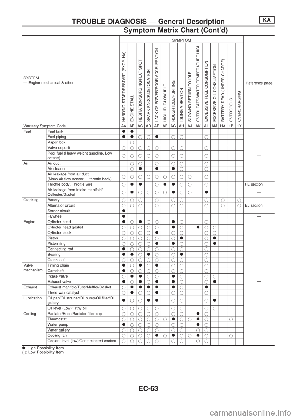
SYSTEM
Ð Engine mechanical & otherSYMPTOM
Reference page
HARD/NO START/RESTART (EXCP. HA)
ENGINE STALL
HESITATION/SURGING/FLAT SPOT
SPARK KNOCK/DETONATION
LACK OF POWER/POOR ACCELERATION
HIGH IDLE/LOW IDLE
ROUGH IDLE/HUNTING
IDLING VIBRATION
SLOW/NO RETURN TO IDLE
OVERHEATS/WATER TEMPERATURE HIGH
EXCESSIVE FUEL CONSUMPTION
EXCESSIVE OIL CONSUMPTION
BATTERY DEAD (UNDER CHARGE)
OVERCOOLS
OVERCHARGING
Warranty Symptom Code AA AB AC AD AE AF AG AH AJ AK AL AM HA 1P 1X
Fuel Fuel tank
ll
Ð Fuel piping
lljjljj j
Vapor lockj
Valve depositjjjjj jj j
Poor fuel (Heavy weight gasoline, Low
octane)jjjjj jj j
Air Air ductjjjjj j
Air cleanerj
llljj
Air leakage from air duct
(Mass air flow sensor Ð throttle body)jjjjjjjjj j
Throttle body, Throttle wirej
lljlljj jFE section
Air leakage from intake manifold/
Collector/Gasketj
ljjjjljjlÐ
Cranking Batteryjjjjjj jjj
EL section Alternator circuitjjjjjj jjj
Starter circuit
l
FlywheellÐ
Engine Cylinder head
ljljjljj
Ð Cylinder head gasketjjjjj
ljljj
Cylinder blockjjjj
ljj jj
Pistonjjjjj j
ljl
Piston ringjjjjlljjl
Connecting rodljjjj jj j
Bearing
lljljjlj
Crankshaftjjjjj jj j
Valve
mechanismTiming chain
ljljljj j
Camshaft
ljjjj jj j
Intake valvej
lljjljjj
Exhaust valve
ljljlljjl
Exhaust Exhaust manifold/Tube/Muffler/Gasketjllll ljl
Three way catalystjljjljj j
Lubrication Oil pan/Oil strainer/Oil pump/Oil filter/Oil
gallery
ljjlljj jl
Oil level (Low)/Filthy oiljjjjj jj jj
Cooling Radiator/Hose/Radiator filler capjjjjj jj
lj
Thermostatjjjjjj
ljjljj
Water pump
ljjjj jjlj
Water galleryjjjjj jj jj
Cooling fanjjjj
ljljjljj
Coolant level (low)/Contaminated coolantjjjjj jj jj
l; High Possibility Item
j; Low Possibility Item
TROUBLE DIAGNOSIS Ð General DescriptionKA
Symptom Matrix Chart (Cont'd)
EC-63
Page 303 of 1659
Fuel Pump
SYSTEM DESCRIPTION
Camshaft position sensorcEngine speed
ECM
(ECCS
control
mod-
ule)
cFuel
pump
relay
Ignition switchcStart signal
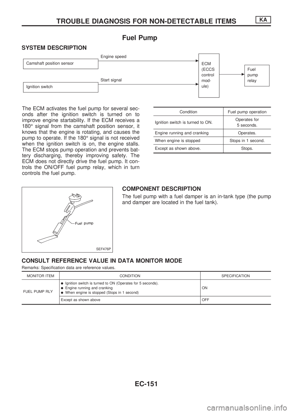
The ECM activates the fuel pump for several sec-
onds after the ignition switch is turned on to
improve engine startability. If the ECM receives a
180É signal from the camshaft position sensor, it
knows that the engine is rotating, and causes the
pump to operate. If the 180É signal is not received
when the ignition switch is on, the engine stalls.
The ECM stops pump operation and prevents bat-
tery discharging, thereby improving safety. The
ECM does not directly drive the fuel pump. It con-
trols the ON/OFF fuel pump relay, which in turn
controls the fuel pump.Condition Fuel pump operation
Ignition switch is turned to ON.Operates for
5 seconds.
Engine running and cranking Operates.
When engine is stopped Stops in 1 second.
Except as shown above. Stops.
COMPONENT DESCRIPTION
The fuel pump with a fuel damper is an in-tank type (the pump
and damper are located in the fuel tank).
CONSULT REFERENCE VALUE IN DATA MONITOR MODE
Remarks: Specification data are reference values.
MONITOR ITEM CONDITION SPECIFICATION
FUEL PUMP RLY
lIgnition switch is turned to ON (Operates for 5 seconds).lEngine running and crankinglWhen engine is stopped (Stops in 1 second)ON
Except as shown above OFF
SEF476P
TROUBLE DIAGNOSIS FOR NON-DETECTABLE ITEMSKA
EC-151
Page 388 of 1659

ELECTRICAL SYSTEM
SECTION
EL
When you read wiring diagrams:
lRead GI section, ``HOW TO READ WIRING DIAGRAMS''.
When you perform trouble diagnoses, read GI section, ``HOW TO FOLLOW FLOW CHART IN
TROUBLE DIAGNOSES'' and ``HOW TO PERFORM EFFICIENT DIAGNOSIS FOR AN ELECTRI-
CAL INCIDENT''.
CONTENTS
PRECAUTIONS......................................................... 1
Supplemental Restraint System (SRS) ``AIR
BAG'' (4WD models).............................................. 1
Supplemental Restraint System (SRS) ``AIR
BAG'' (2WD models).............................................. 1
HARNESS CONNECTOR.......................................... 2
Description ............................................................. 2
STANDARDIZED RELAY.......................................... 3
Description ............................................................. 3
POWER SUPPLY ROUTING..................................... 5
Schematic .............................................................. 5
Wiring Diagram - POWER -................................... 6
Fuse ..................................................................... 13
Fusible Link .......................................................... 13
Circuit Breaker Inspection.................................... 13
GROUND DISTRIBUTION....................................... 14
BATTERY................................................................. 18
How to Handle Battery......................................... 18
Battery Test and Charging Chart......................... 21
Service Data and Specifications (SDS) ............... 25
STARTING SYSTEM............................................... 26
Wiring Diagram - START - .................................. 26
Trouble Diagnoses ............................................... 27
Construction ......................................................... 28
Removal and Installation ..................................... 30
Inspection ............................................................. 30
Assembly.............................................................. 32
Service Data and Specifications (SDS) ............... 33
CHARGING SYSTEM.............................................. 34
Wiring Diagram - CHARGE -/Gasoline Engine ... 34
Wiring Diagram - CHARGE -/Diesel Engine ....... 35Trouble Diagnoses ............................................... 36
Construction ......................................................... 38
Removal and Installation ..................................... 39
Disassembly ......................................................... 39
Inspection ............................................................. 39
Assembly.............................................................. 40
Service Data and Specifications (SDS) ............... 41
COMBINATION SWITCH........................................ 42
Check ................................................................... 42
Replacement ........................................................ 43
HEADLAMP - Conventional Type -....................... 44
Wiring Diagram - H/LAMP -/LHD Models ............ 44
Wiring Diagram - H/LAMP -/RHD Models ........... 46
Trouble Diagnoses ............................................... 48
Bulb Replacement................................................ 49
Aiming Adjustment ............................................... 49
Low Beam ............................................................ 50
HEADLAMP - Daytime Light System -................. 51
System Description .............................................. 51
Schematic ............................................................ 53
Wiring Diagram - DTRL - ..................................... 54
Trouble Diagnoses ............................................... 57
Bulb Replacement................................................ 57
Aiming Adjustment ............................................... 57
HEADLAMP - Dim-dip Lamp System -................. 58
System Description .............................................. 58
Schematic ............................................................ 58
Wiring Diagram - DIMDIP -.................................. 59
Trouble Diagnoses ............................................... 62
Bulb Replacement................................................ 62
Aiming Adjustment ............................................... 62
EL
Page 408 of 1659
CAUTION:
If it becomes necessary to start the engine with a booster
battery and jumper cables,
a. Use a 12-volt booster battery.
b. After connecting battery cables, ensure that they are
tightly clamped to battery terminals for good contact.
c. Never add distilled water through the hole used to check
specific gravity.
How to Handle Battery
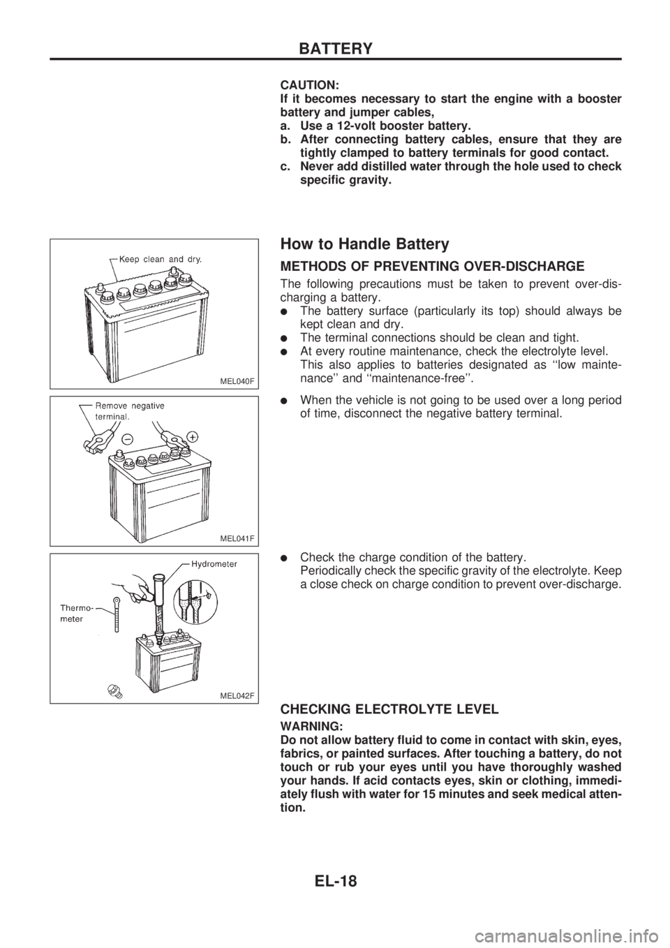
METHODS OF PREVENTING OVER-DISCHARGE
The following precautions must be taken to prevent over-dis-
charging a battery.
lThe battery surface (particularly its top) should always be
kept clean and dry.
lThe terminal connections should be clean and tight.
lAt every routine maintenance, check the electrolyte level.
This also applies to batteries designated as ``low mainte-
nance'' and ``maintenance-free''.
lWhen the vehicle is not going to be used over a long period
of time, disconnect the negative battery terminal.
lCheck the charge condition of the battery.
Periodically check the specific gravity of the electrolyte. Keep
a close check on charge condition to prevent over-discharge.
CHECKING ELECTROLYTE LEVEL
WARNING:
Do not allow battery fluid to come in contact with skin, eyes,
fabrics, or painted surfaces. After touching a battery, do not
touch or rub your eyes until you have thoroughly washed
your hands. If acid contacts eyes, skin or clothing, immedi-
ately flush with water for 15 minutes and seek medical atten-
tion.
MEL040F
MEL041F
MEL042F
BATTERY
EL-18
Page 409 of 1659
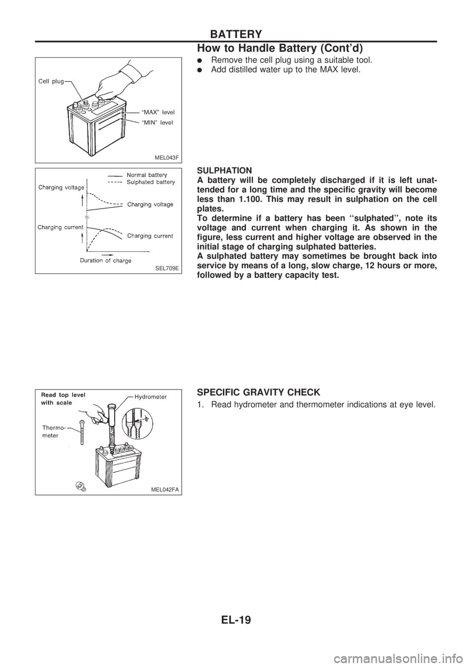
lRemove the cell plug using a suitable tool.
lAdd distilled water up to the MAX level.
SULPHATION
A battery will be completely discharged if it is left unat-
tended for a long time and the specific gravity will become
less than 1.100. This may result in sulphation on the cell
plates.
To determine if a battery has been ``sulphated'', note its
voltage and current when charging it. As shown in the
figure, less current and higher voltage are observed in the
initial stage of charging sulphated batteries.
A sulphated battery may sometimes be brought back into
service by means of a long, slow charge, 12 hours or more,
followed by a battery capacity test.
SPECIFIC GRAVITY CHECK
1. Read hydrometer and thermometer indications at eye level.
MEL043F
SEL709E
MEL042FA
BATTERY
How to Handle Battery (Cont'd)
EL-19
Page 411 of 1659
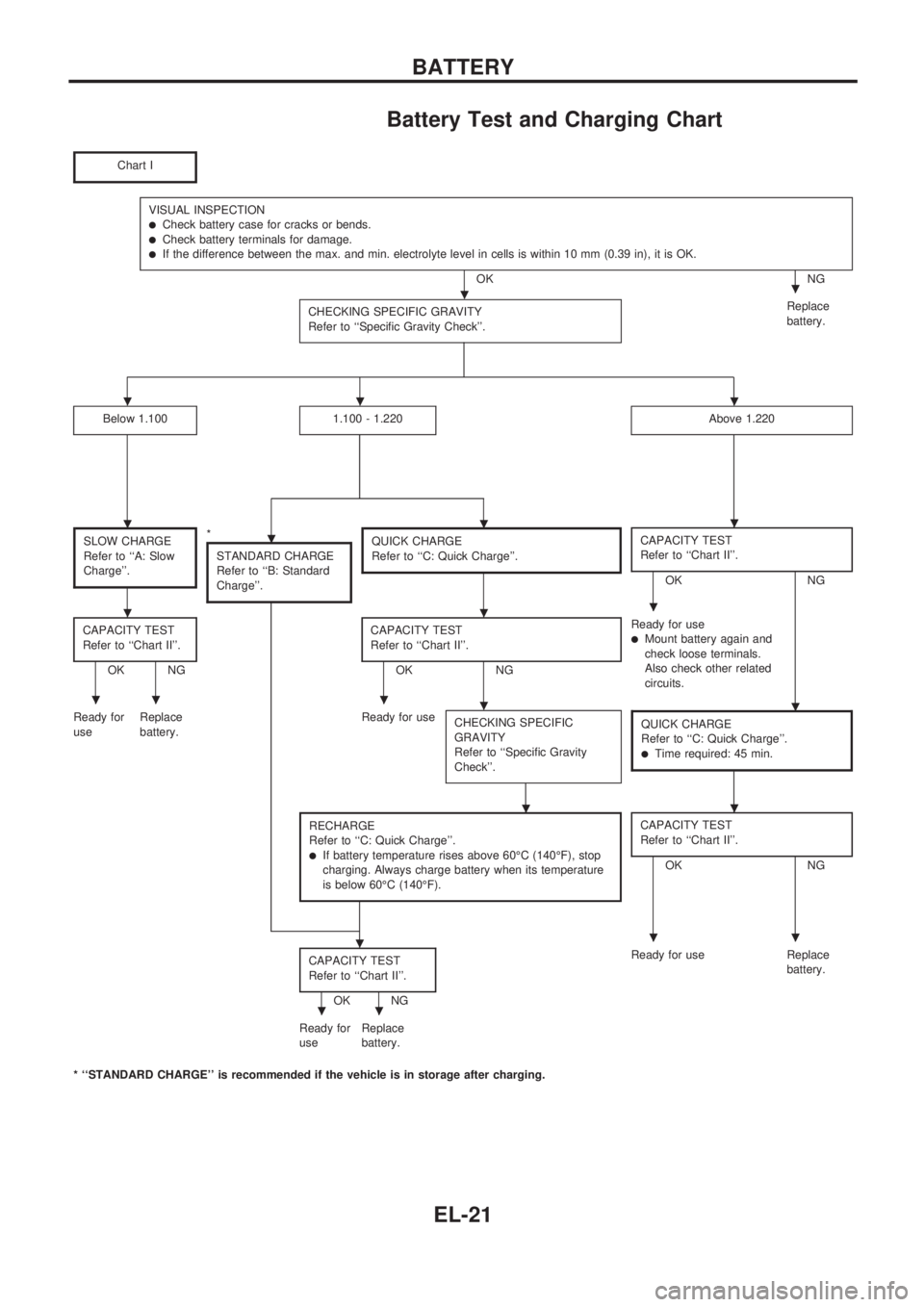
Battery Test and Charging Chart
Chart I
VISUAL INSPECTIONlCheck battery case for cracks or bends.lCheck battery terminals for damage.lIf the difference between the max. and min. electrolyte level in cells is within 10 mm (0.39 in), it is OK.
OK NG
CHECKING SPECIFIC GRAVITY
Refer to ``Specific Gravity Check''.
Replace
battery.
Below 1.1001.100 - 1.220Above 1.220
SLOW CHARGE
Refer to ``A: Slow
Charge''.*
STANDARD CHARGE
Refer to ``B: Standard
Charge''.QUICK CHARGE
Refer to ``C: Quick Charge''.CAPACITY TEST
Refer to ``Chart II''.
OK NG
CAPACITY TEST
Refer to ``Chart II''.
OK NGCAPACITY TEST
Refer to ``Chart II''.OK NGReady for use
lMount battery again and
check loose terminals.
Also check other related
circuits.
Ready for
useReplace
battery.Ready for use
CHECKING SPECIFIC
GRAVITY
Refer to ``Specific Gravity
Check''.
QUICK CHARGE
Refer to ``C: Quick Charge''.
lTime required: 45 min.
RECHARGE
Refer to ``C: Quick Charge''.
lIf battery temperature rises above 60ÉC (140ÉF), stop
charging. Always charge battery when its temperature
is below 60ÉC (140ÉF).
CAPACITY TEST
Refer to ``Chart II''.
OK NG
CAPACITY TEST
Refer to ``Chart II''.
OK NGReady for use Replace
battery.
Ready for
useReplace
battery.
* ``STANDARD CHARGE'' is recommended if the vehicle is in storage after charging.
..
...
....
...
.....
..
...
..
BATTERY
EL-21
Page 412 of 1659
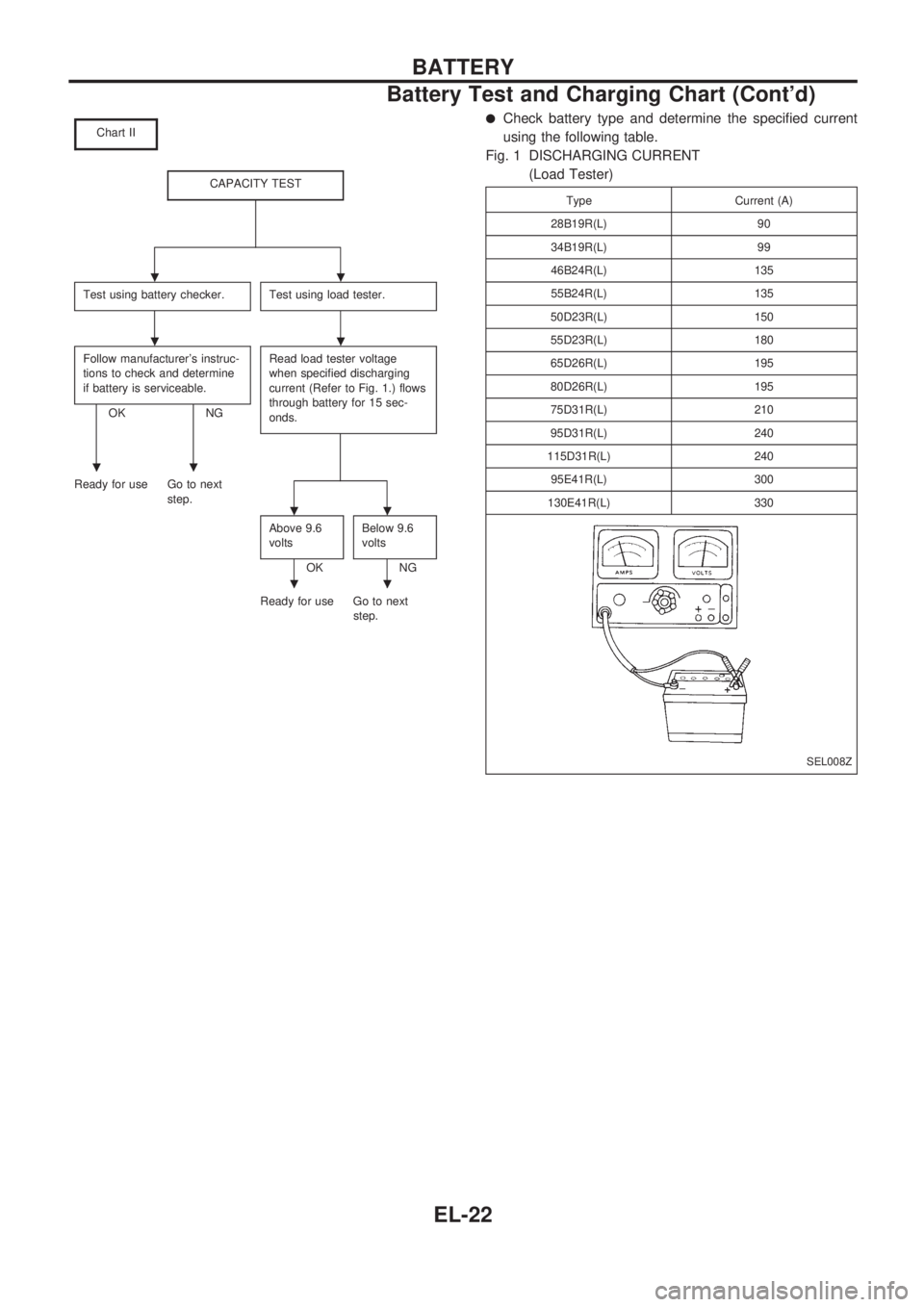
Chart II
CAPACITY TEST
Test using battery checker.Test using load tester.
Follow manufacturer's instruc-
tions to check and determine
if battery is serviceable.
OK NGRead load tester voltage
when specified discharging
current (Refer to Fig. 1.) flows
through battery for 15 sec-
onds.
Ready for use Go to next
step.
Above 9.6
volts
OKBelow 9.6
voltsNG
Ready for use Go to next
step.
lCheck battery type and determine the specified current
using the following table.
Fig. 1 DISCHARGING CURRENT
(Load Tester)
Type Current (A)
28B19R(L) 90
34B19R(L) 99
46B24R(L) 135
55B24R(L) 135
50D23R(L) 150
55D23R(L) 180
65D26R(L) 195
80D26R(L) 195
75D31R(L) 210
95D31R(L) 240
115D31R(L) 240
95E41R(L) 300
130E41R(L) 330
SEL008Z
..
..
..
..
..
BATTERY
Battery Test and Charging Chart (Cont'd)
EL-22