Page 15 of 1659
Inspection
Check brake pedal for following items:
lBrake pedal bend
lClevis pin deformation
lCrack of any welded portion
lCrack or deformation of clevis pin stopper
Adjustment
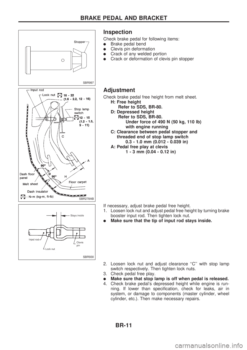
Check brake pedal free height from melt sheet.
H: Free height
Refer to SDS, BR-80.
D: Depressed height
Refer to SDS, BR-80.
Under force of 490 N (50 kg, 110 lb)
with engine running
C: Clearance between pedal stopper and
threaded end of stop lamp switch
0.3 - 1.0 mm (0.012 - 0.039 in)
A: Pedal free play at clevis
1-3mm(0.04 - 0.12 in)
If necessary, adjust brake pedal free height.
1. Loosen lock nut and adjust pedal free height by turning brake
booster input rod. Then tighten lock nut.
lMake sure that the tip of input rod stays inside.
2. Loosen lock nut and adjust clearance ``C'' with stop lamp
switch respectively. Then tighten lock nuts.
3. Check pedal free play.
lMake sure that stop lamp is off when pedal is released.
4. Check brake pedal's depressed height while engine is run-
ning. If lower than specification, check for leaks, air in
system, or damage to components (master cylinder, wheel
cylinder, etc.). Then make necessary repairs.
SBR997
SBR278AB
SBR930
BRAKE PEDAL AND BRACKET
BR-11
Page 20 of 1659
Installation
CAUTION:
lBe careful not to deform or bend brake pipes during
installation of booster.
lReplace clevis pin if damaged.
lRefill with new brake fluid DOT 3 or DOT 4*1.
lNever reuse drained brake fluid.
lTake care not to damage brake booster mounting bolt
thread when installing. Due to the narrow angle of
installation, the threads can be damaged by the dash
panel.
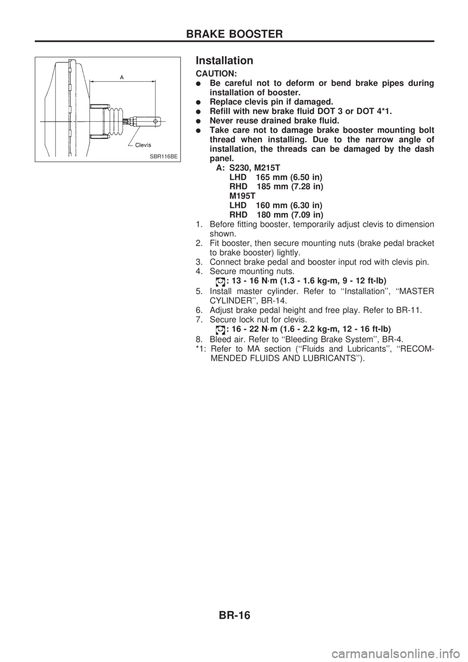
A: S230, M215T
LHD 165 mm (6.50 in)
RHD 185 mm (7.28 in)
M195T
LHD 160 mm (6.30 in)
RHD 180 mm (7.09 in)
1. Before fitting booster, temporarily adjust clevis to dimension
shown.
2. Fit booster, then secure mounting nuts (brake pedal bracket
to brake booster) lightly.
3. Connect brake pedal and booster input rod with clevis pin.
4. Secure mounting nuts.
: 13 - 16 N´m (1.3 - 1.6 kg-m,9-12ft-lb)
5. Install master cylinder. Refer to ``Installation'', ``MASTER
CYLINDER'', BR-14.
6. Adjust brake pedal height and free play. Refer to BR-11.
7. Secure lock nut for clevis.
: 16 - 22 N´m (1.6 - 2.2 kg-m, 12 - 16 ft-lb)
8. Bleed air. Refer to ``Bleeding Brake System'', BR-4.
*1: Refer to MA section (``Fluids and Lubricants'', ``RECOM-
MENDED FLUIDS AND LUBRICANTS'').
SBR116BE
BRAKE BOOSTER
BR-16
Page 84 of 1659

Inspection and Adjustment
DISC BRAKEUnit: mm (in)
Brake model CL28VD
Pad wear limit
Minimum thickness 2.0 (0.079)
Rotor repair limit
Minimum thickness 24.0 (0.945)
DRUM BRAKEUnit: mm (in)
Brake model LT26B LT30A
Lining wear limit
Minimum thickness 1.5 (0.059)
Drum repair limit
Maximum inner
diameter261.5 (10.30) 296.5 (11.67)
Out-of-round limit 0.15 (0.0059)
BRAKE PEDALUnit: mm (in)
Free height ``H''*
LHD 209 - 219 (8.23 - 8.62)
RHD 203 - 213 (7.99 - 8.39)
Depressed height ``D''
[under force of 490 N (50
kg, 110 lb) with engine run-
ning]120.0 (4.72)
Clearance ``C'' between
pedal stopper and threaded
end of stop lamp switch0.3 - 1.0 (0.012 - 0.039)
Pedal free play
At clevis 1.0 - 3.0 (0.039 - 0.118)
At pedal pad 4 - 12 (0.16 - 0.47)
*: Measured from surface of melt sheet to pedal pad.
PARKING BRAKE CONTROL
Control type Stick lever Center lever
Lever stroke
[under force of 196 N
(20 kg, 44 lb)]2WD 8 - 10 Ð
4WD 10-12 8-10
Lever stroke when warning
switch comes on1
SERVICE DATA AND SPECIFICATIONS (SDS)
BR-80
Page 90 of 1659
Adjusting Clutch Pedal
1. Adjust pedal height with pedal stopper.
2. Adjust pedal free play with push rod.
Air Bleeding Procedure
Bleed air according to the following procedure.
Bleed the air from the master cylinder (RHD models only)
and then the operating cylinder.
1. Fill the master cylinder reservoir tank with new brake fluid.
2. Connect a transparent vinyl hose to the air bleeder.
3. Slowly depress the clutch pedal to its full stroke length and
release it completely. Repeat this operation several times at
2 to 3 second intervals.
4. Open the air bleeder with the clutch pedal fully depressed.
5. Close the air bleeder.
6. Release the clutch pedal and wait at least 5 seconds.
7. Repeat steps 3 through 6 above until air bubbles no longer
appear in the brake fluid.
SCL742-A
.LHD model
221 - 231 mm (8.70 - 0.09 in)
RHD model
195 - 205 mm (7.68 - 8.07 in)
Pedal free play ``A'':
1 - 1.5 mm (0.039 - 0.059 in)
SCL203
INSPECTION AND ADJUSTMENT
CL-5
Page 98 of 1659
INSTALLATION
lApply recommended grease to contact surface of spline por-
tion.
Too much lubricant might cause clutch disc facing damage.
Clutch Cover
INSPECTION
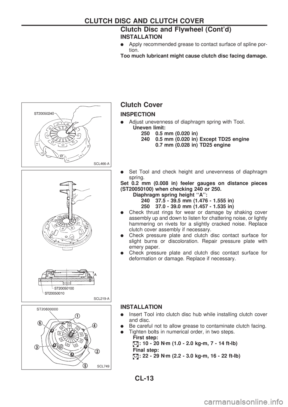
lAdjust unevenness of diaphragm spring with Tool.
Uneven limit:
250 0.5 mm (0.020 in)
240 0.5 mm (0.020 in) Except TD25 engine
0.7 mm (0.028 in) TD25 engine
lSet Tool and check height and unevenness of diaphragm
spring.
Set 0.2 mm (0.008 in) feeler gauges on distance pieces
(ST20050100) when checking 240 or 250.
Diaphragm spring height ``A'':
240 37.5 - 39.5 mm (1.476 - 1.555 in)
250 37.0 - 39.0 mm (1.457 - 1.535 in)
lCheck thrust rings for wear or damage by shaking cover
assembly up and down to listen for chattering noise, or lightly
hammering on rivets for a slightly cracked noise. Replace
clutch cover assembly if necessary.
lCheck pressure plate and clutch disc contact surface for
slight burns or discoloration. Repair pressure plate with
emery paper.
lCheck pressure plate and clutch disc contact surface for
deformation or damage. Replace if necessary.
INSTALLATION
lInsert Tool into clutch disc hub while installing clutch cover
and disc.
lBe careful not to allow grease to contaminate clutch facing.
lTighten bolts in numerical order, in two steps.
First step:
:10-20Nzm (1.0 - 2.0 kg-m,7-14ft-lb)
Final step:
:22-29Nzm (2.2 - 3.0 kg-m, 16 - 22 ft-lb)
SCL466-A
SCL219-A
SCL749
CLUTCH DISC AND CLUTCH COVER
Clutch Disc and Flywheel (Cont'd)
CL-13
Page 99 of 1659
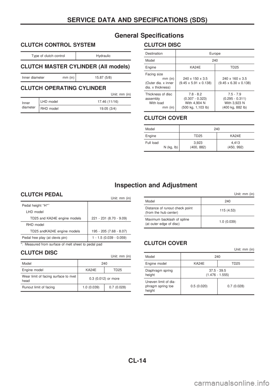
General Specifications
CLUTCH CONTROL SYSTEM
Type of clutch control Hydraulic
CLUTCH MASTER CYLINDER (All models)
Inner diameter mm (in) 15.87 (5/8)
CLUTCH OPERATING CYLINDER
Unit: mm (in)
Inner
diameterLHD model 17.46 (11/16)
RHD model 19.05 (3/4)
CLUTCH DISC
Destination Europe
Model 240
Engine KA24E TD25
Facing size
mm (in)
(Outer dia. x inner
dia. x thickness)240 x 150 x 3.5
(9.45 x 5.91 x 0.138)240 x 160 x 3.5
(9.45 x 6.30 x 0.138)
Thickness of disc
assembly
With load
mm (in)7.8 - 8.2
(0.307 - 0.323)
With 4,904 N
(500 kg, 1,103 lb)7.5 - 7.9
(0.295 - 0.311)
With 3,923 N
(400 kg, 882 lb)
CLUTCH COVER
Model 240
Engine TD25 KA24E
Full load
N (kg, lb)3,923
(400, 882)4,413
(450, 992)
Inspection and Adjustment
CLUTCH PEDALUnit: mm (in)
Pedal height ``H*''
LHD model
TD25 and KA24E engine models 221 - 231 (8.70 - 9.09)
RHD model
TD25 andKA24E engine models 195 - 205 (7.68 - 8.07)
Pedal free play (at clevis pin) 1 - 1.5 (0.039 - 0.059)
*: Measured from surface of melt sheet to pedal pad
CLUTCH DISCUnit: mm (in)
Model 240
Engine model KA24E TD25
Wear limit of facing surface to rivet
head0.3 (0.012) or more
Runout limit of facing 1.0 (0.039) 0.7 (0.028)
Unit: mm (in)
Model 240
Distance of runout check point
(from the hub center)115 (4.53)
Maximum backlash of spline
(at outer edge of disc)1.0 (0.039)
CLUTCH COVER
Unit: mm (in)
Model 240
Engine model KA24E TD25
Diaphragm spring
height37.5 - 39.5
(1.476 - 1.555)
Uneven limit of dia-
phragm spring toe
height0.5 (0.020) 0.7 (0.028)
SERVICE DATA AND SPECIFICATIONS (SDS)
CL-14
Page 282 of 1659
COMPONENT INSPECTION
Heated oxygen sensor heater
Check resistance between terminalsV3andV1.
Resistance: 2.3 - 4.3Wat 25ÉC (77ÉF)
Check continuity between terminals
V2andV1,V3andV2.
Continuity should not exist.
If NG, replace the heated oxygen sensor.
CAUTION:
Discard any heated oxygen sensor which has been dropped
from a height of more than 0.5 m (19.7 in) onto a hard sur-
face such as a concrete floor; use a new one.
SEF586Q
TROUBLE DIAGNOSIS FOR NON-DETECTABLE ITEMSKA
Heated Oxygen Sensor Heater
Ð LHD Models Ð (Cont'd)
EC-130
Page 423 of 1659
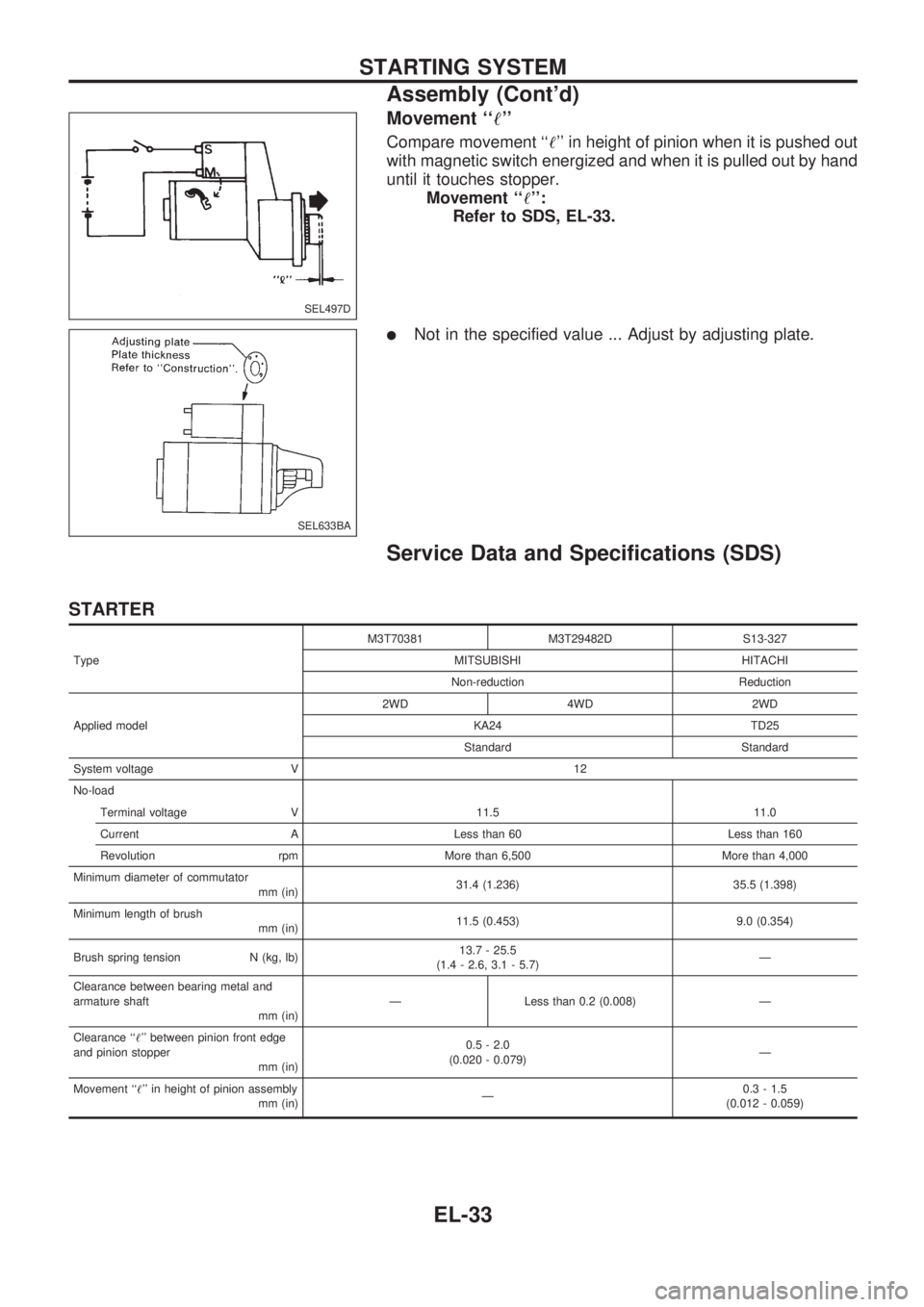
Movement ``!''
Compare movement ``!'' in height of pinion when it is pushed out
with magnetic switch energized and when it is pulled out by hand
until it touches stopper.
Movement ``!'':
Refer to SDS, EL-33.
lNot in the specified value ... Adjust by adjusting plate.
Service Data and Specifications (SDS)
STARTER
TypeM3T70381 M3T29482D S13-327
MITSUBISHI HITACHI
Non-reduction Reduction
Applied model2WD 4WD 2WD
KA24 TD25
Standard Standard
System voltage V 12
No-load
Terminal voltage V 11.5 11.0
Current A Less than 60 Less than 160
Revolution rpm More than 6,500 More than 4,000
Minimum diameter of commutator
mm (in)31.4 (1.236) 35.5 (1.398)
Minimum length of brush
mm (in)11.5 (0.453) 9.0 (0.354)
Brush spring tension N (kg, lb)13.7 - 25.5
(1.4 - 2.6, 3.1 - 5.7)Ð
Clearance between bearing metal and
armature shaft
mm (in)Ð Less than 0.2 (0.008) Ð
Clearance ``!'' between pinion front edge
and pinion stopper
mm (in)0.5 - 2.0
(0.020 - 0.079)Ð
Movement ``!'' in height of pinion assembly
mm (in)Ð0.3 - 1.5
(0.012 - 0.059)
SEL497D
SEL633BA
STARTING SYSTEM
Assembly (Cont'd)
EL-33