1998 NISSAN PICK-UP height
[x] Cancel search: heightPage 795 of 1659
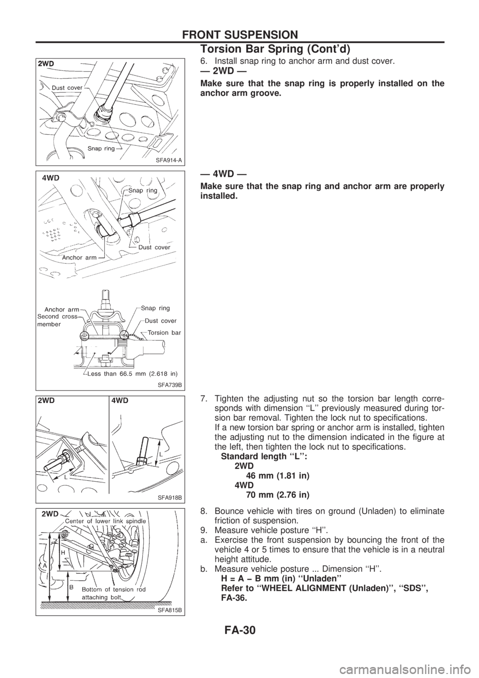
6. Install snap ring to anchor arm and dust cover.
Ð 2WD Ð
Make sure that the snap ring is properly installed on the
anchor arm groove.
Ð 4WD Ð
Make sure that the snap ring and anchor arm are properly
installed.
7. Tighten the adjusting nut so the torsion bar length corre-
sponds with dimension ``L'' previously measured during tor-
sion bar removal. Tighten the lock nut to specifications.
If a new torsion bar spring or anchor arm is installed, tighten
the adjusting nut to the dimension indicated in the figure at
the left, then tighten the lock nut to specifications.
Standard length ``L'':
2WD
46 mm (1.81 in)
4WD
70 mm (2.76 in)
8. Bounce vehicle with tires on ground (Unladen) to eliminate
friction of suspension.
9. Measure vehicle posture ``H''.
a. Exercise the front suspension by bouncing the front of the
vehicle 4 or 5 times to ensure that the vehicle is in a neutral
height attitude.
b. Measure vehicle posture ... Dimension ``H''.
H=AþBmm(in) ``Unladen''
Refer to ``WHEEL ALIGNMENT (Unladen)'', ``SDS'',
FA-36.
SFA914-A
SFA739B
SFA918B
SFA815B
FRONT SUSPENSION
Torsion Bar Spring (Cont'd)
FA-30
Page 796 of 1659
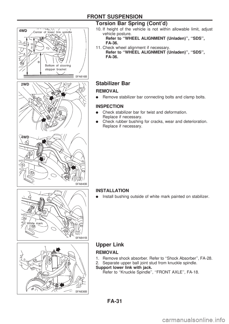
10. If height of the vehicle is not within allowable limit, adjust
vehicle posture.
Refer to ``WHEEL ALIGNMENT (Unladen)'', ``SDS'',
FA-36.
11. Check wheel alignment if necessary.
Refer to ``WHEEL ALIGNMENT (Unladen)'', ``SDS'',
FA-36.
Stabilizer Bar
REMOVAL
lRemove stabilizer bar connecting bolts and clamp bolts.
INSPECTION
lCheck stabilizer bar for twist and deformation.
Replace if necessary.
lCheck rubber bushing for cracks, wear and deterioration.
Replace if necessary.
INSTALLATION
lInstall bushing outside of white mark painted on stabilizer.
Upper Link
REMOVAL
1. Remove shock absorber. Refer to ``Shock Absorber'', FA-28.
2. Separate upper ball joint stud from knuckle spindle.
Support lower link with jack.
Refer to ``Knuckle Spindle'', ``FRONT AXLE'', FA-18.
SFA816B
SFA840B
SFA841B
SFA836B
FRONT SUSPENSION
Torsion Bar Spring (Cont'd)
FA-31
Page 799 of 1659
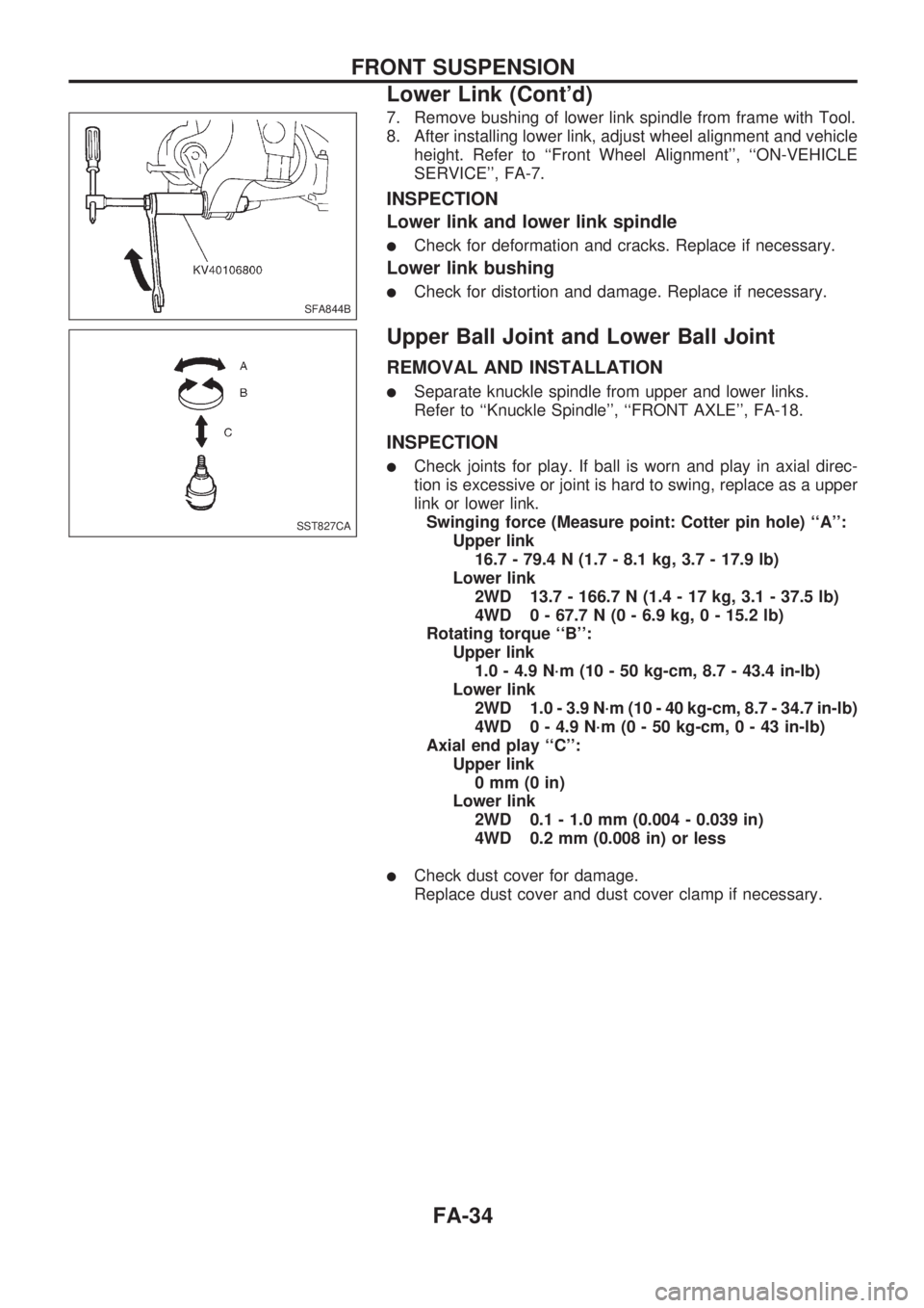
7. Remove bushing of lower link spindle from frame with Tool.
8. After installing lower link, adjust wheel alignment and vehicle
height. Refer to ``Front Wheel Alignment'', ``ON-VEHICLE
SERVICE'', FA-7.
INSPECTION
Lower link and lower link spindle
lCheck for deformation and cracks. Replace if necessary.
Lower link bushing
lCheck for distortion and damage. Replace if necessary.
Upper Ball Joint and Lower Ball Joint
REMOVAL AND INSTALLATION
lSeparate knuckle spindle from upper and lower links.
Refer to ``Knuckle Spindle'', ``FRONT AXLE'', FA-18.
INSPECTION
lCheck joints for play. If ball is worn and play in axial direc-
tion is excessive or joint is hard to swing, replace as a upper
link or lower link.
Swinging force (Measure point: Cotter pin hole) ``A'':
Upper link
16.7 - 79.4 N (1.7 - 8.1 kg, 3.7 - 17.9 lb)
Lower link
2WD 13.7 - 166.7 N (1.4 - 17 kg, 3.1 - 37.5 lb)
4WD 0 - 67.7 N (0 - 6.9 kg, 0 - 15.2 lb)
Rotating torque ``B'':
Upper link
1.0 - 4.9 N´m (10 - 50 kg-cm, 8.7 - 43.4 in-lb)
Lower link
2WD 1.0 - 3.9 N´m (10 - 40 kg-cm, 8.7 - 34.7 in-lb)
4WD 0 - 4.9 N´m (0 - 50 kg-cm,0-43in-lb)
Axial end play ``C'':
Upper link
0mm(0in)
Lower link
2WD 0.1 - 1.0 mm (0.004 - 0.039 in)
4WD 0.2 mm (0.008 in) or less
lCheck dust cover for damage.
Replace dust cover and dust cover clamp if necessary.
SFA844B
SST827CA
FRONT SUSPENSION
Lower Link (Cont'd)
FA-34
Page 801 of 1659
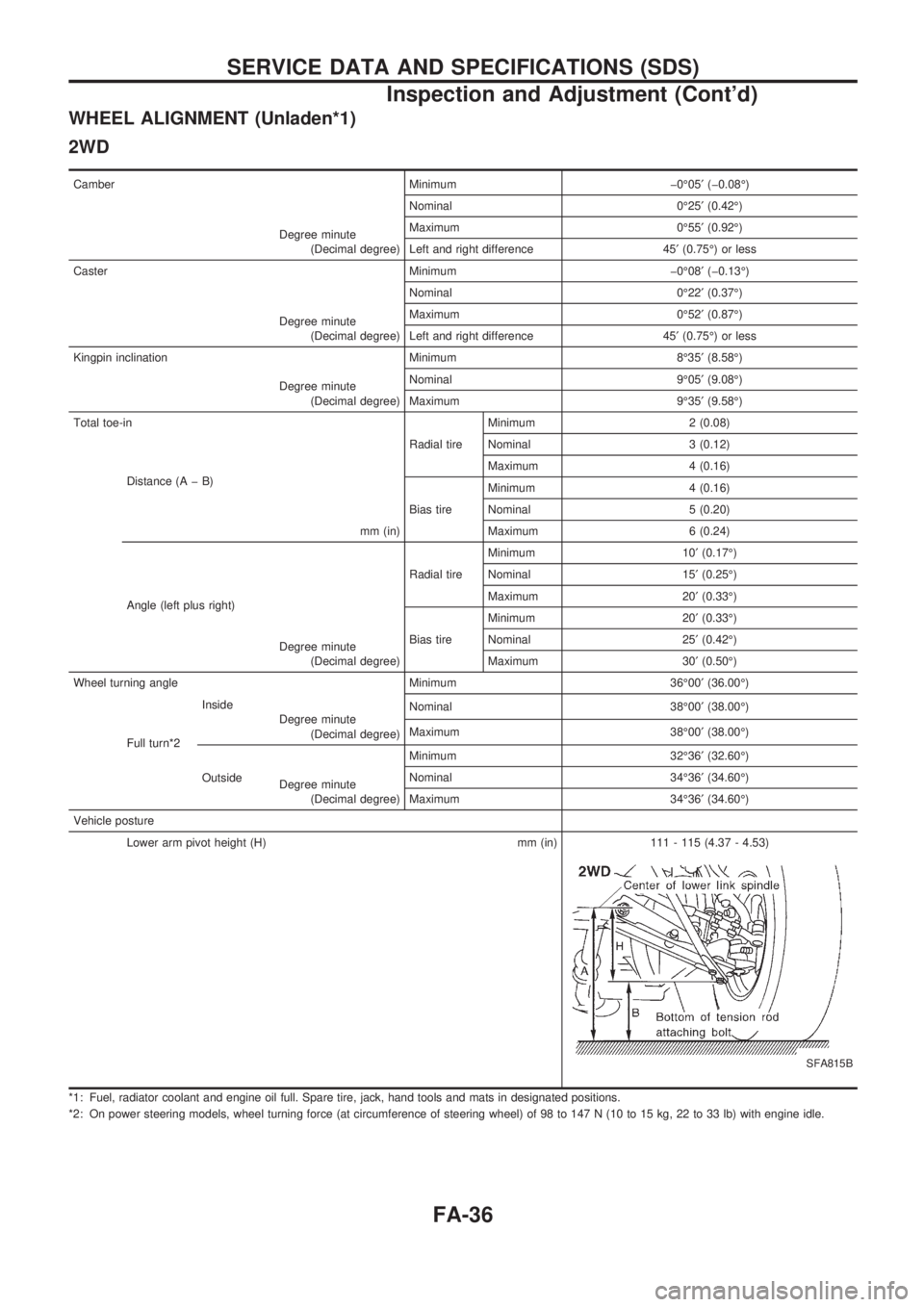
WHEEL ALIGNMENT (Unladen*1)
2WD
Camber Minimum þ0É05¢(þ0.08É)
Degree minute
(Decimal degree)Nominal 0É25¢(0.42É)
Maximum 0É55¢(0.92É)
Left and right difference 45¢(0.75É) or less
Caster Minimum þ0É08¢(þ0.13É)
Degree minute
(Decimal degree)Nominal 0É22¢(0.37É)
Maximum 0É52¢(0.87É)
Left and right difference 45¢(0.75É) or less
Kingpin inclination Minimum 8É35¢(8.58É)
Degree minute
(Decimal degree)Nominal 9É05¢(9.08É)
Maximum 9É35¢(9.58É)
Total toe-in
Radial tireMinimum 2 (0.08)
Distance (A þ B)
mm (in)Nominal 3 (0.12)
Maximum 4 (0.16)
Bias tireMinimum 4 (0.16)
Nominal 5 (0.20)
Maximum 6 (0.24)
Angle (left plus right)
Degree minute
(Decimal degree)Radial tireMinimum 10¢(0.17É)
Nominal 15¢(0.25É)
Maximum 20¢(0.33É)
Bias tireMinimum 20¢(0.33É)
Nominal 25¢(0.42É)
Maximum 30¢(0.50É)
Wheel turning angle Minimum 36É00¢(36.00É)
Full turn*2Inside
Degree minute
(Decimal degree)Nominal 38É00¢(38.00É)
Maximum 38É00¢(38.00É)
OutsideMinimum 32É36¢(32.60É)
Degree minute
(Decimal degree)Nominal 34É36¢(34.60É)
Maximum 34É36¢(34.60É)
Vehicle posture
Lower arm pivot height (H) mm (in) 111 - 115 (4.37 - 4.53)
SFA815B
*1: Fuel, radiator coolant and engine oil full. Spare tire, jack, hand tools and mats in designated positions.
*2: On power steering models, wheel turning force (at circumference of steering wheel) of 98 to 147 N (10 to 15 kg, 22 to 33 lb) with engine idle.
SERVICE DATA AND SPECIFICATIONS (SDS)
Inspection and Adjustment (Cont'd)
FA-36
Page 802 of 1659
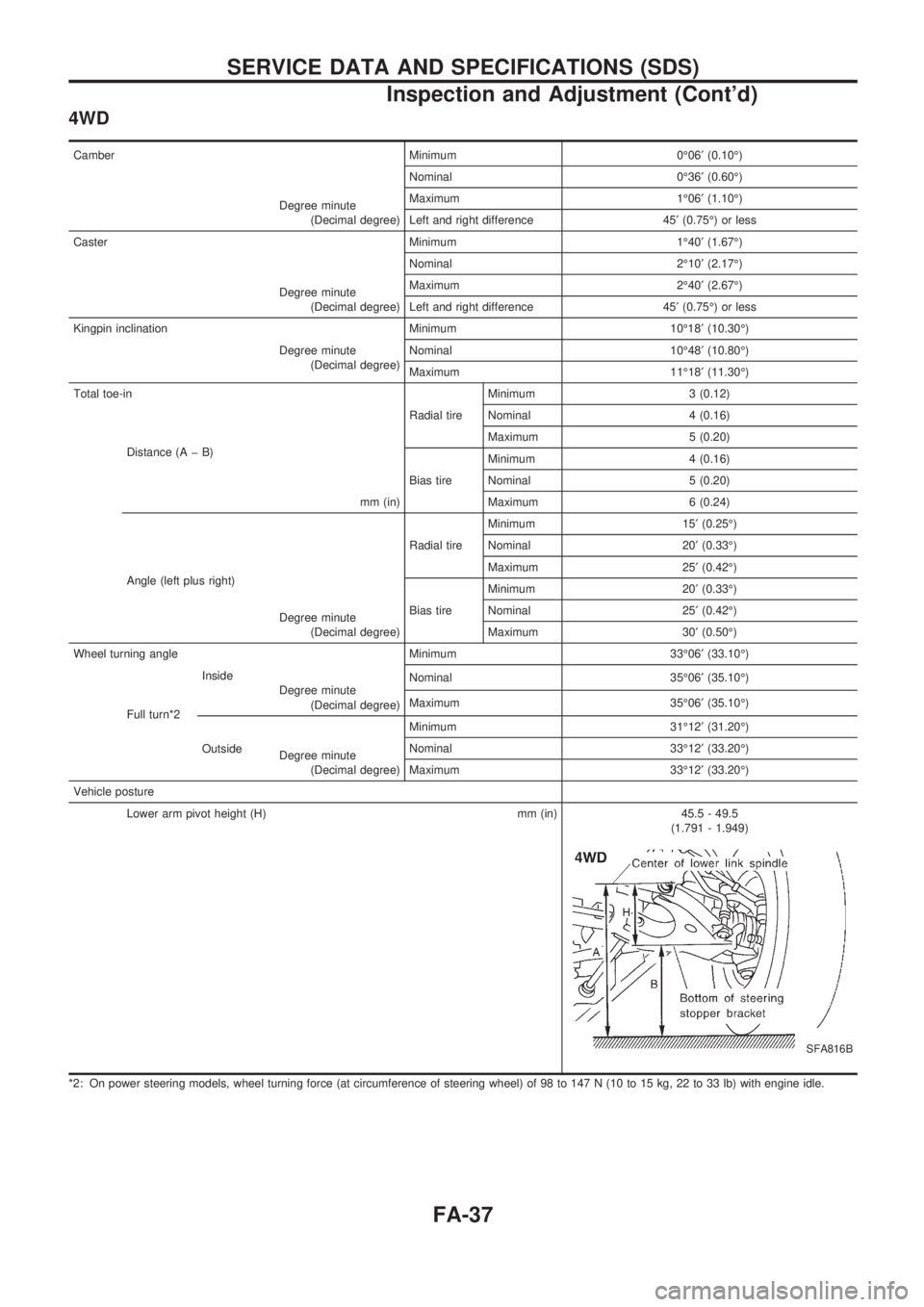
4WD
Camber Minimum 0É06¢(0.10É)
Degree minute
(Decimal degree)Nominal 0É36¢(0.60É)
Maximum 1É06¢(1.10É)
Left and right difference 45¢(0.75É) or less
Caster Minimum 1É40¢(1.67É)
Degree minute
(Decimal degree)Nominal 2É10¢(2.17É)
Maximum 2É40¢(2.67É)
Left and right difference 45¢(0.75É) or less
Kingpin inclination Minimum 10É18¢(10.30É)
Degree minute
(Decimal degree)Nominal 10É48¢(10.80É)
Maximum 11É18¢(11.30É)
Total toe-in
Radial tireMinimum 3 (0.12)
Distance (A þ B)
mm (in)Nominal 4 (0.16)
Maximum 5 (0.20)
Bias tireMinimum 4 (0.16)
Nominal 5 (0.20)
Maximum 6 (0.24)
Angle (left plus right)
Degree minute
(Decimal degree)Radial tireMinimum 15¢(0.25É)
Nominal 20¢(0.33É)
Maximum 25¢(0.42É)
Bias tireMinimum 20¢(0.33É)
Nominal 25¢(0.42É)
Maximum 30¢(0.50É)
Wheel turning angle Minimum 33É06¢(33.10É)
Full turn*2Inside
Degree minute
(Decimal degree)Nominal 35É06¢(35.10É)
Maximum 35É06¢(35.10É)
OutsideMinimum 31É12¢(31.20É)
Degree minute
(Decimal degree)Nominal 33É12¢(33.20É)
Maximum 33É12¢(33.20É)
Vehicle posture
Lower arm pivot height (H) mm (in) 45.5 - 49.5
(1.791 - 1.949)
SFA816B
*2: On power steering models, wheel turning force (at circumference of steering wheel) of 98 to 147 N (10 to 15 kg, 22 to 33 lb) with engine idle.
SERVICE DATA AND SPECIFICATIONS (SDS)
Inspection and Adjustment (Cont'd)
FA-37
Page 848 of 1659
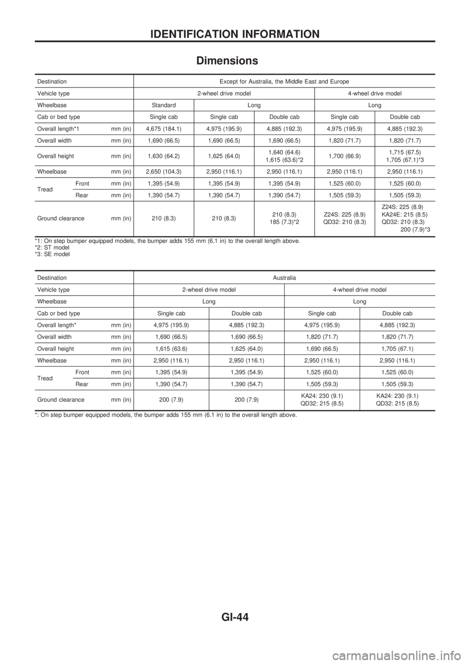
Dimensions
Destination Except for Australia, the Middle East and Europe
Vehicle type 2-wheel drive model 4-wheel drive model
Wheelbase Standard Long Long
Cab or bed type Single cab Single cab Double cab Single cab Double cab
Overall length*1 mm (in) 4,675 (184.1) 4,975 (195.9) 4,885 (192.3) 4,975 (195.9) 4,885 (192.3)
Overall width mm (in) 1,690 (66.5) 1,690 (66.5) 1,690 (66.5) 1,820 (71.7) 1,820 (71.7)
Overall height mm (in) 1,630 (64.2) 1,625 (64.0)1,640 (64.6)
1,615 (63.6)*21,700 (66.9)1,715 (67.5)
1,705 (67.1)*3
Wheelbase mm (in) 2,650 (104.3) 2,950 (116.1) 2,950 (116.1) 2,950 (116.1) 2,950 (116.1)
TreadFront mm (in) 1,395 (54.9) 1,395 (54.9) 1,395 (54.9) 1,525 (60.0) 1,525 (60.0)
Rear mm (in) 1,390 (54.7) 1,390 (54.7) 1,390 (54.7) 1,505 (59.3) 1,505 (59.3)
Ground clearance mm (in) 210 (8.3) 210 (8.3)210 (8.3)
185 (7.3)*2Z24S: 225 (8.9)
QD32: 210 (8.3)Z24S: 225 (8.9)
KA24E: 215 (8.5)
QD32: 210 (8.3)
200 (7.9)*3
*1: On step bumper equipped models, the bumper adds 155 mm (6.1 in) to the overall length above.
*2: ST model
*3: SE model
DestinationAustralia
Vehicle type 2-wheel drive model 4-wheel drive model
Wheelbase Long Long
Cab or bed type Single cab Double cab Single cab Double cab
Overall length* mm (in) 4,975 (195.9) 4,885 (192.3) 4,975 (195.9) 4,885 (192.3)
Overall width mm (in) 1,690 (66.5) 1,690 (66.5) 1,820 (71.7) 1,820 (71.7)
Overall height mm (in) 1,615 (63.6) 1,625 (64.0) 1,690 (66.5) 1,705 (67.1)
Wheelbase mm (in) 2,950 (116.1) 2,950 (116.1) 2,950 (116.1) 2,950 (116.1)
TreadFront mm (in) 1,395 (54.9) 1,395 (54.9) 1,525 (60.0) 1,525 (60.0)
Rear mm (in) 1,390 (54.7) 1,390 (54.7) 1,505 (59.3) 1,505 (59.3)
Ground clearance mm (in) 200 (7.9) 200 (7.9)KA24: 230 (9.1)
QD32: 215 (8.5)KA24: 230 (9.1)
QD32: 215 (8.5)
*: On step bumper equipped models, the bumper adds 155 mm (6.1 in) to the overall length above.
IDENTIFICATION INFORMATION
GI-44
Page 849 of 1659
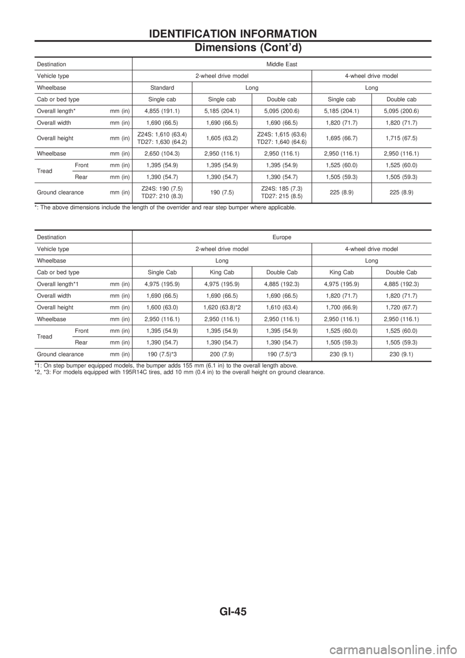
DestinationMiddle East
Vehicle type 2-wheel drive model 4-wheel drive model
Wheelbase Standard Long Long
Cab or bed type Single cab Single cab Double cab Single cab Double cab
Overall length* mm (in) 4,855 (191.1) 5,185 (204.1) 5,095 (200.6) 5,185 (204.1) 5,095 (200.6)
Overall width mm (in) 1,690 (66.5) 1,690 (66.5) 1,690 (66.5) 1,820 (71.7) 1,820 (71.7)
Overall height mm (in)Z24S: 1,610 (63.4)
TD27: 1,630 (64.2)1,605 (63.2)Z24S: 1,615 (63.6)
TD27: 1,640 (64.6)1,695 (66.7) 1,715 (67.5)
Wheelbase mm (in) 2,650 (104.3) 2,950 (116.1) 2,950 (116.1) 2,950 (116.1) 2,950 (116.1)
TreadFront mm (in) 1,395 (54.9) 1,395 (54.9) 1,395 (54.9) 1,525 (60.0) 1,525 (60.0)
Rear mm (in) 1,390 (54.7) 1,390 (54.7) 1,390 (54.7) 1,505 (59.3) 1,505 (59.3)
Ground clearance mm (in)Z24S: 190 (7.5)
TD27: 210 (8.3)190 (7.5)Z24S: 185 (7.3)
TD27: 215 (8.5)225 (8.9) 225 (8.9)
*: The above dimensions include the length of the overrider and rear step bumper where applicable.
DestinationEurope
Vehicle type 2-wheel drive model 4-wheel drive model
Wheelbase Long Long
Cab or bed type Single Cab King Cab Double Cab King Cab Double Cab
Overall length*1 mm (in) 4,975 (195.9) 4,975 (195.9) 4,885 (192.3) 4,975 (195.9) 4,885 (192.3)
Overall width mm (in) 1,690 (66.5) 1,690 (66.5) 1,690 (66.5) 1,820 (71.7) 1,820 (71.7)
Overall height mm (in) 1,600 (63.0) 1,620 (63.8)*2 1,610 (63.4) 1,700 (66.9) 1,720 (67.7)
Wheelbase mm (in) 2,950 (116.1) 2,950 (116.1) 2,950 (116.1) 2,950 (116.1) 2,950 (116.1)
TreadFront mm (in) 1,395 (54.9) 1,395 (54.9) 1,395 (54.9) 1,525 (60.0) 1,525 (60.0)
Rear mm (in) 1,390 (54.7) 1,390 (54.7) 1,390 (54.7) 1,505 (59.3) 1,505 (59.3)
Ground clearance mm (in) 190 (7.5)*3 200 (7.9) 190 (7.5)*3 230 (9.1) 230 (9.1)
*1: On step bumper equipped models, the bumper adds 155 mm (6.1 in) to the overall length above.
*2, *3: For models equipped with 195R14C tires, add 10 mm (0.4 in) to the overall height on ground clearance.
IDENTIFICATION INFORMATION
Dimensions (Cont'd)
GI-45
Page 865 of 1659
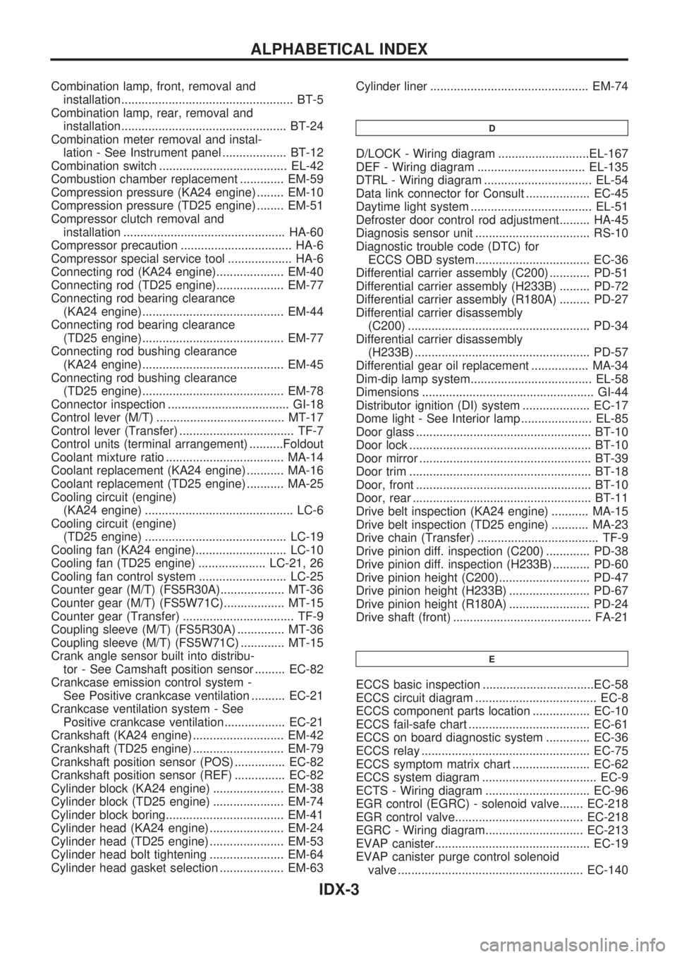
Combination lamp, front, removal and
installation................................................... BT-5
Combination lamp, rear, removal and
installation................................................. BT-24
Combination meter removal and instal-
lation - See Instrument panel ................... BT-12
Combination switch ...................................... EL-42
Combustion chamber replacement ............. EM-59
Compression pressure (KA24 engine) ........ EM-10
Compression pressure (TD25 engine) ........ EM-51
Compressor clutch removal and
installation ................................................ HA-60
Compressor precaution ................................. HA-6
Compressor special service tool ................... HA-6
Connecting rod (KA24 engine).................... EM-40
Connecting rod (TD25 engine).................... EM-77
Connecting rod bearing clearance
(KA24 engine).......................................... EM-44
Connecting rod bearing clearance
(TD25 engine).......................................... EM-77
Connecting rod bushing clearance
(KA24 engine).......................................... EM-45
Connecting rod bushing clearance
(TD25 engine).......................................... EM-78
Connector inspection .................................... GI-18
Control lever (M/T) ...................................... MT-17
Control lever (Transfer) .................................. TF-7
Control units (terminal arrangement) ..........Foldout
Coolant mixture ratio ................................... MA-14
Coolant replacement (KA24 engine) ........... MA-16
Coolant replacement (TD25 engine) ........... MA-25
Cooling circuit (engine)
(KA24 engine) ............................................ LC-6
Cooling circuit (engine)
(TD25 engine) .......................................... LC-19
Cooling fan (KA24 engine)........................... LC-10
Cooling fan (TD25 engine) .................... LC-21, 26
Cooling fan control system .......................... LC-25
Counter gear (M/T) (FS5R30A)................... MT-36
Counter gear (M/T) (FS5W71C).................. MT-15
Counter gear (Transfer) ................................. TF-9
Coupling sleeve (M/T) (FS5R30A) .............. MT-36
Coupling sleeve (M/T) (FS5W71C) ............. MT-15
Crank angle sensor built into distribu-
tor - See Camshaft position sensor ......... EC-82
Crankcase emission control system -
See Positive crankcase ventilation .......... EC-21
Crankcase ventilation system - See
Positive crankcase ventilation.................. EC-21
Crankshaft (KA24 engine) ........................... EM-42
Crankshaft (TD25 engine) ........................... EM-79
Crankshaft position sensor (POS) ............... EC-82
Crankshaft position sensor (REF) ............... EC-82
Cylinder block (KA24 engine) ..................... EM-38
Cylinder block (TD25 engine) ..................... EM-74
Cylinder block boring................................... EM-41
Cylinder head (KA24 engine) ...................... EM-24
Cylinder head (TD25 engine) ...................... EM-53
Cylinder head bolt tightening ...................... EM-64
Cylinder head gasket selection ................... EM-63Cylinder liner ............................................... EM-74
D
D/LOCK - Wiring diagram ...........................EL-167
DEF - Wiring diagram ................................ EL-135
DTRL - Wiring diagram ................................ EL-54
Data link connector for Consult ................... EC-45
Daytime light system .................................... EL-51
Defroster door control rod adjustment......... HA-45
Diagnosis sensor unit .................................. RS-10
Diagnostic trouble code (DTC) for
ECCS OBD system.................................. EC-36
Differential carrier assembly (C200) ............ PD-51
Differential carrier assembly (H233B) ......... PD-72
Differential carrier assembly (R180A) ......... PD-27
Differential carrier disassembly
(C200) ...................................................... PD-34
Differential carrier disassembly
(H233B) .................................................... PD-57
Differential gear oil replacement ................. MA-34
Dim-dip lamp system.................................... EL-58
Dimensions ................................................... GI-44
Distributor ignition (DI) system .................... EC-17
Dome light - See Interior lamp ..................... EL-85
Door glass .................................................... BT-10
Door lock ...................................................... BT-10
Door mirror ................................................... BT-39
Door trim ...................................................... BT-18
Door, front .................................................... BT-10
Door, rear ..................................................... BT-11
Drive belt inspection (KA24 engine) ........... MA-15
Drive belt inspection (TD25 engine) ........... MA-23
Drive chain (Transfer) .................................... TF-9
Drive pinion diff. inspection (C200) ............. PD-38
Drive pinion diff. inspection (H233B) ........... PD-60
Drive pinion height (C200)........................... PD-47
Drive pinion height (H233B) ........................ PD-67
Drive pinion height (R180A) ........................ PD-24
Drive shaft (front) ......................................... FA-21
E
ECCS basic inspection .................................EC-58
ECCS circuit diagram .................................... EC-8
ECCS component parts location ................. EC-10
ECCS fail-safe chart .................................... EC-61
ECCS on board diagnostic system ............. EC-36
ECCS relay .................................................. EC-75
ECCS symptom matrix chart ....................... EC-62
ECCS system diagram .................................. EC-9
ECTS - Wiring diagram ............................... EC-96
EGR control (EGRC) - solenoid valve....... EC-218
EGR control valve...................................... EC-218
EGRC - Wiring diagram............................. EC-213
EVAP canister.............................................. EC-19
EVAP canister purge control solenoid
valve ....................................................... EC-140
ALPHABETICAL INDEX
IDX-3