1998 NISSAN PICK-UP air conditioning
[x] Cancel search: air conditioningPage 150 of 1659

ENGINE CONTROL SYSTEM
SECTION
EC
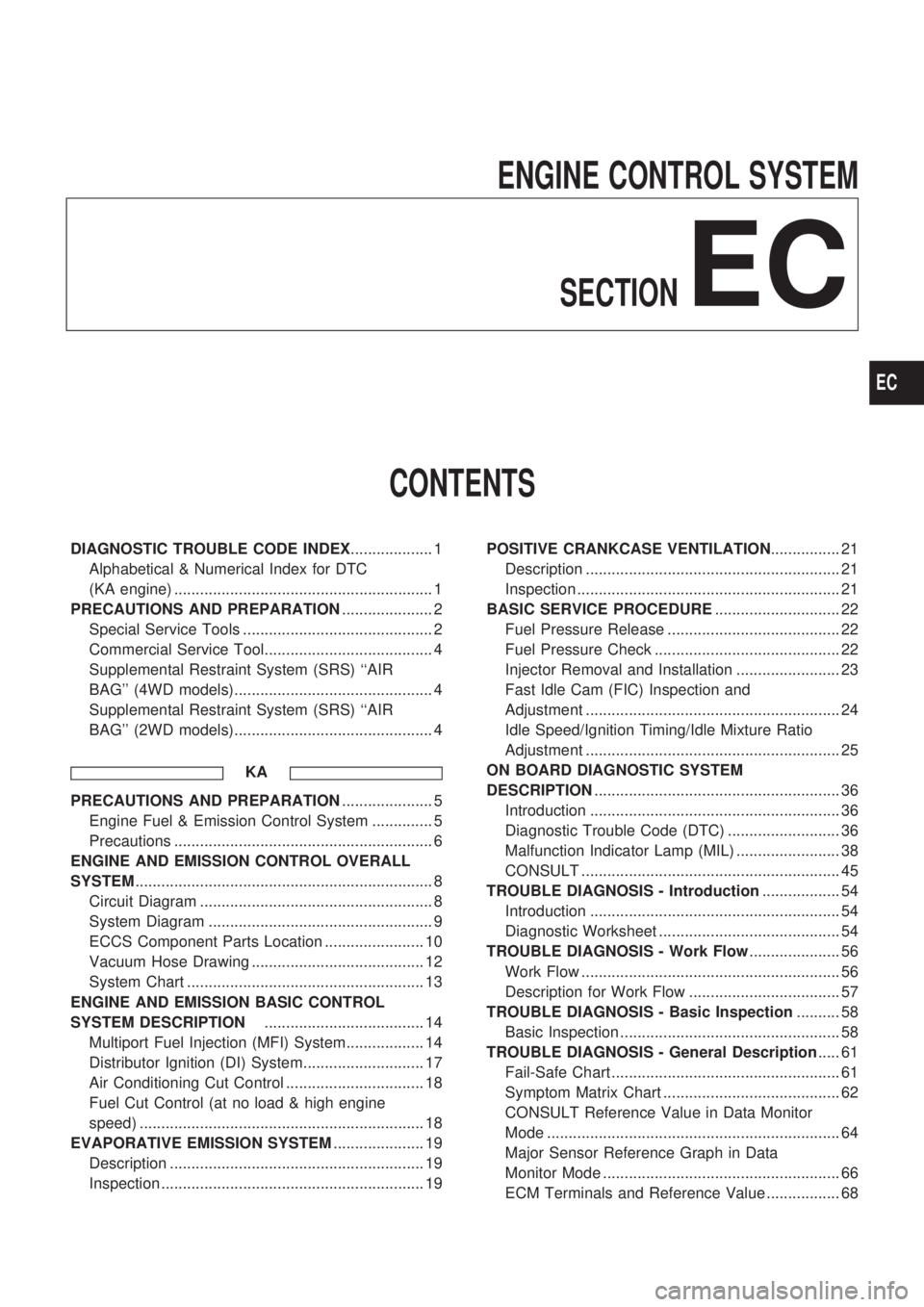
CONTENTS
DIAGNOSTIC TROUBLE CODE INDEX................... 1
Alphabetical & Numerical Index for DTC
(KA engine) ............................................................ 1
PRECAUTIONS AND PREPARATION..................... 2
Special Service Tools ............................................ 2
Commercial Service Tool....................................... 4
Supplemental Restraint System (SRS) ``AIR
BAG'' (4WD models).............................................. 4
Supplemental Restraint System (SRS) ``AIR
BAG'' (2WD models).............................................. 4
KA
PRECAUTIONS AND PREPARATION..................... 5
Engine Fuel & Emission Control System .............. 5
Precautions ............................................................ 6
ENGINE AND EMISSION CONTROL OVERALL
SYSTEM..................................................................... 8
Circuit Diagram ...................................................... 8
System Diagram .................................................... 9
ECCS Component Parts Location ....................... 10
Vacuum Hose Drawing ........................................ 12
System Chart ....................................................... 13
ENGINE AND EMISSION BASIC CONTROL
SYSTEM DESCRIPTION..................................... 14
Multiport Fuel Injection (MFI) System.................. 14
Distributor Ignition (DI) System............................ 17
Air Conditioning Cut Control ................................ 18
Fuel Cut Control (at no load & high engine
speed) .................................................................. 18
EVAPORATIVE EMISSION SYSTEM..................... 19
Description ........................................................... 19
Inspection ............................................................. 19POSITIVE CRANKCASE VENTILATION................ 21
Description ........................................................... 21
Inspection ............................................................. 21
BASIC SERVICE PROCEDURE............................. 22
Fuel Pressure Release ........................................ 22
Fuel Pressure Check ........................................... 22
Injector Removal and Installation ........................ 23
Fast Idle Cam (FIC) Inspection and
Adjustment ........................................................... 24
Idle Speed/Ignition Timing/Idle Mixture Ratio
Adjustment ........................................................... 25
ON BOARD DIAGNOSTIC SYSTEM
DESCRIPTION......................................................... 36
Introduction .......................................................... 36
Diagnostic Trouble Code (DTC) .......................... 36
Malfunction Indicator Lamp (MIL) ........................ 38
CONSULT ............................................................ 45
TROUBLE DIAGNOSIS - Introduction.................. 54
Introduction .......................................................... 54
Diagnostic Worksheet .......................................... 54
TROUBLE DIAGNOSIS - Work Flow..................... 56
Work Flow ............................................................ 56
Description for Work Flow ................................... 57
TROUBLE DIAGNOSIS - Basic Inspection.......... 58
Basic Inspection ................................................... 58
TROUBLE DIAGNOSIS - General Description..... 61
Fail-Safe Chart ..................................................... 61
Symptom Matrix Chart ......................................... 62
CONSULT Reference Value in Data Monitor
Mode .................................................................... 64
Major Sensor Reference Graph in Data
Monitor Mode ....................................................... 66
ECM Terminals and Reference Value ................. 68
EC
Page 170 of 1659

Air Conditioning Cut Control
INPUT/OUTPUT SIGNAL LINE
Air conditioner switchcAir conditioner ``ON'' signal
ECM
(ECCS
control
module)
cAir condi-
tioner
relayThrottle position sensorcThrottle valve opening angle
Ignition switch
cStart signal
Engine coolant temperature sensor
cEngine coolant temperature
SYSTEM DESCRIPTION
This system improves engine operation when the
air conditioner is used.
Under the following conditions, the air conditioner
is turned off.
lWhen the accelerator pedal is fully depressed
lWhen cranking the engine
lWhen the engine coolant temperature becomes
excessively high
Fuel Cut Control (at no load & high engine
speed)
INPUT/OUTPUT SIGNAL LINE
Vehicle speed sensorcVehicle speed
ECM
(ECCS
control
module)
cInjectors
Neutral position switchcNeutral position
Throttle position sensor
cThrottle position
Engine coolant temperature sensor
cEngine coolant temperature
Camshaft position sensor
cEngine speed
If the engine speed is above 3,500 rpm with no load (for
example, in neutral and engine speed over 3,500 rpm) fuel will
be cut off after some time. The exact time when the fuel is cut
off varies based on engine speed.
Fuel cut will operate until the engine speed reaches 1,500 rpm,
then fuel cut is cancelled.
NOTE:
This function is different than deceleration control listed
under multiport fuel injection on EC-14.
ENGINE AND EMISSION BASIC CONTROL SYSTEM DESCRIPTIONKA
EC-18
Page 804 of 1659

GENERAL INFORMATION
SECTION
GI
CONTENTS
PRECAUTIONS......................................................... 1
Precautions for Supplemental Restraint
System (SRS) ``AIR BAG'' (4WD models)............. 1
Precautions for Supplemental Restraint
System (SRS) ``AIR BAG'' (2WD models)............. 1
Precautions for NATS ............................................ 2
General Precautions .............................................. 2
Precautions for Multiport Fuel Injection System
or ECCS Engine .................................................... 4
Precautions for Three Way Catalyst
(If so equipped) ...................................................... 4
Precautions for Engine Oils ................................... 4
Precautions for Fuel............................................... 5
Precautions for Air Conditioning ............................ 6
HOW TO USE THIS MANUAL.................................. 7
HOW TO READ WIRING DIAGRAMS...................... 9
Sample/Wiring Diagram - EXAMPL - .................... 9
Description ........................................................... 11
HOW TO CHECK TERMINAL................................. 18
How to Probe Connectors ................................... 18
How to Check Enlarged Contact Spring of
Terminal ............................................................... 19
Waterproof Connector Inspection ........................ 20
Terminal Lock Inspection ..................................... 20
HOW TO PERFORM EFFICIENT DIAGNOSIS
FOR AN ELECTRICAL INCIDENT......................... 21
Work Flow ............................................................ 21HOW TO PERFORM EFFICIENT DIAGNOSIS...... 22
Incident Simulation Tests..................................... 22
Circuit Inspection ................................................. 25
HOW TO FOLLOW FLOW CHART IN
TROUBLE DIAGNOSES......................................... 31
How to Follow This Flow Chart ........................... 32
CONSULT CHECKING SYSTEM............................ 34
Function and System Application ........................ 34
Lithium Battery Replacement............................... 34
Checking Equipment ............................................ 35
Loading Procedure............................................... 36
CONSULT Data Link Connector (DLC) Circuit ... 36
IDENTIFICATION INFORMATION.......................... 37
Model Variation .................................................... 37
Identification Number ........................................... 40
Dimensions .......................................................... 44
Wheels and Tires ................................................. 46
LIFTING POINTS AND TOW TRUCK TOWING..... 47
Pantograph Jack .................................................. 47
Screw Jack........................................................... 48
Garage Jack and Safety Stand ........................... 49
2-pole Lift ............................................................. 50
Tow Truck Towing ............................................... 51
Towing Point ........................................................ 53
TIGHTENING TORQUE OF STANDARD BOLTS.. 54
SAE J1930 TERMINOLOGY LIST.......................... 55
SAE J1930 Terminology List ............................... 55
GI
Page 810 of 1659

DIESEL ENGINE*:
For Europe: diesel fuel of above 50 cetane
* If two types of diesel fuel are available, use summer or win-
ter fuel properly according to the following temperature con-
ditions.
lAbove þ7ÉC (20ÉF) ... Summer type diesel fuel.
lBelow þ7ÉC (20ÉF) ... Winter type diesel fuel.
CAUTION:
lDo not use home heating oil, gasoline, or other alternate
fuels in your diesel engine. The use of those can cause
engine damage.
lDo not use summer fuel at temperature below þ7ÉC
(20ÉF). The cold temperature will cause wax to form in
the fuel. As a result, it may prevent the engine from run-
ning smoothly.
lDo not add gasoline or other alternate fuels to diesel
fuel.
Precautions for Air Conditioning
Use an approved refrigerant recovery unit any time the air con-
ditioning system must be discharged. Refer to HA section
(``HFC-134a (R-134a) Service Procedure'', ``SERVICE PRO-
CEDURES'') for specific instructions.
PRECAUTIONS
Precautions for Fuel (Cont'd)
GI-6
Page 873 of 1659

Precautions for Working with HFC-134a
(R-134a)
WARNING:
lCFC-12 (R-12) refrigerant and HFC-134a (R-134a) refrigerant are not compatible. These refrig-
erants must never be mixed, even in the smallest amounts. If the refrigerants are mixed, com-
pressor failure is likely to occur.
lUse only specified lubricant for the HFC-134a (R-134a) A/C system and HFC-134a (R-134a) com-
ponents. If lubricant other than that specified is used, compressor failure is likely to occur.
lThe specified HFC-134a (R-134a) lubricant rapidly absorbs moisture from the atmosphere. The
following handling precautions must be observed:
a: When removing refrigerant components from a vehicle, immediately cap (seal) the compo-
nent to minimize the entry of moisture from the atmosphere.
b: When installing refrigerant components to a vehicle, do not remove the caps (unseal) until
just before connecting the components. Connect all refrigerant loop components as quickly
as possible to minimize the entry of moisture into system.
c: Only use the specified lubricant from a sealed container. Immediately reseal containers of
lubricant. Without proper sealing, lubricant will become moisture saturated and should not
be used.
d: Avoid breathing A/C refrigerant and lubricant vapor or mist. Exposure may irritate eyes,
nose and throat. Use only approved recovery/recycling equipment to discharge HFC-134a
(R-134a) refrigerant. If accidental system discharge occurs, ventilate work area before
resuming service. Additional health and safety information may be obtained from refriger-
ant and lubricant manufacturers.
e: Do not allow lubricant (Nissan A/C System Oil Type S) to come in contact with styrofoam
parts. Damage may result.
General Refrigerant Precautions
WARNING:
lDo not release refrigerant into the air. Use approved recovery/recycling equipment to capture the
refrigerant every time an air conditioning system is discharged.
lAlways wear eye and hand protection (goggles and gloves) when working with any refrigerant or
air conditioning system.
lDo not store or heat refrigerant containers above 52ÉC (125ÉF).
lDo not heat a refrigerant container with an open flame; if container warming is required, place
the bottom of the container in a warm pail of water.
lDo not intentionally drop, puncture, or incinerate refrigerant containers.
lKeep refrigerant away from open flames: poisonous gas will be produced if refrigerant burns.
lRefrigerant will displace oxygen, therefore be certain to work in well ventilated areas to prevent
suffocation.
lDo not introduce compressed air to any refrigerant container or refrigerant component.
Precautions for Refrigerant Connection
A new type refrigerant connection has been introduced to all refrigerant lines except the following location.
lExpansion valve to cooling unit
lCondenser to liquid tank
FEATURES OF NEW TYPE REFRIGERANT CONNECTION
lThe O-ring has been relocated. It has also been provided with a groove for proper installation. This
eliminates the chance of the O-ring being caught in, or damaged by, the mating part. The sealing direc-
tion of the O-ring is now set vertically in relation to the contacting surface of the mating part to improve
sealing characteristics.
lThe reaction force of the O-ring will not occur in the direction that causes the joint to pull out, thereby
facilitating piping connections.
PRECAUTIONS AND PREPARATION
HA-2