Page 532 of 1659

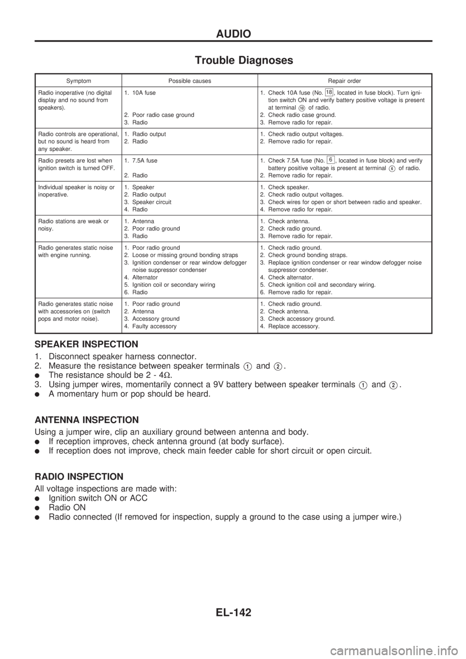
Trouble Diagnoses
Symptom Possible causes Repair order
Radio inoperative (no digital
display and no sound from
speakers).1. 10A fuse
2. Poor radio case ground
3. Radio1. Check 10A fuse (No.
18, located in fuse block). Turn igni-
tion switch ON and verify battery positive voltage is present
at terminal
V10of radio.
2. Check radio case ground.
3. Remove radio for repair.
Radio controls are operational,
but no sound is heard from
any speaker.1. Radio output
2. Radio1. Check radio output voltages.
2. Remove radio for repair.
Radio presets are lost when
ignition switch is turned OFF.1. 7.5A fuse
2. Radio1. Check 7.5A fuse (No.
6, located in fuse block) and verify
battery positive voltage is present at terminal
V6of radio.
2. Remove radio for repair.
Individual speaker is noisy or
inoperative.1. Speaker
2. Radio output
3. Speaker circuit
4. Radio1. Check speaker.
2. Check radio output voltages.
3. Check wires for open or short between radio and speaker.
4. Remove radio for repair.
Radio stations are weak or
noisy.1. Antenna
2. Poor radio ground
3. Radio1. Check antenna.
2. Check radio ground.
3. Remove radio for repair.
Radio generates static noise
with engine running.1. Poor radio ground
2. Loose or missing ground bonding straps
3. Ignition condenser or rear window defogger
noise suppressor condenser
4. Alternator
5. Ignition coil or secondary wiring
6. Radio1. Check radio ground.
2. Check ground bonding straps.
3. Replace ignition condenser or rear window defogger noise
suppressor condenser.
4. Check alternator.
5. Check ignition coil and secondary wiring.
6. Remove radio for repair.
Radio generates static noise
with accessories on (switch
pops and motor noise).1. Poor radio ground
2. Antenna
3. Accessory ground
4. Faulty accessory1. Check radio ground.
2. Check antenna.
3. Check accessory ground.
4. Replace accessory.
SPEAKER INSPECTION
1. Disconnect speaker harness connector.
2. Measure the resistance between speaker terminals
V1andV2.
lThe resistance should be2-4W.
3. Using jumper wires, momentarily connect a 9V battery between speaker terminals
V1andV2.
lA momentary hum or pop should be heard.
ANTENNA INSPECTION
Using a jumper wire, clip an auxiliary ground between antenna and body.
lIf reception improves, check antenna ground (at body surface).
lIf reception does not improve, check main feeder cable for short circuit or open circuit.
RADIO INSPECTION
All voltage inspections are made with:
lIgnition switch ON or ACC
lRadio ON
lRadio connected (If removed for inspection, supply a ground to the case using a jumper wire.)
AUDIO
EL-142
Page 538 of 1659
Power Antenna
TROUBLE DIAGNOSES
Symptom Possible causes Repair order
Power antenna does not oper-
ate.1. 7.5A fuse
2. Radio signal
3. Grounds
E6andE39
1. Check 7.5A fuse (No.6, located in fuse block). Verify that
battery positive voltage is present at terminal
V1of power
antenna.
2. Turn ignition switch and radio ON. Verify that battery positive
voltage is present at terminal
V3of power antenna.
3. Check groundsE6andE39.
LOCATION OF ANTENNA
ANTENNA ROD REPLACEMENT
Removal
1. Remove antenna nut and antenna base.
2. Withdraw antenna rod while raising it by operating antenna
motor.
SEL339V
SEL240V
SEL341V
AUDIO ANTENNA
EL-148
Page 1440 of 1659

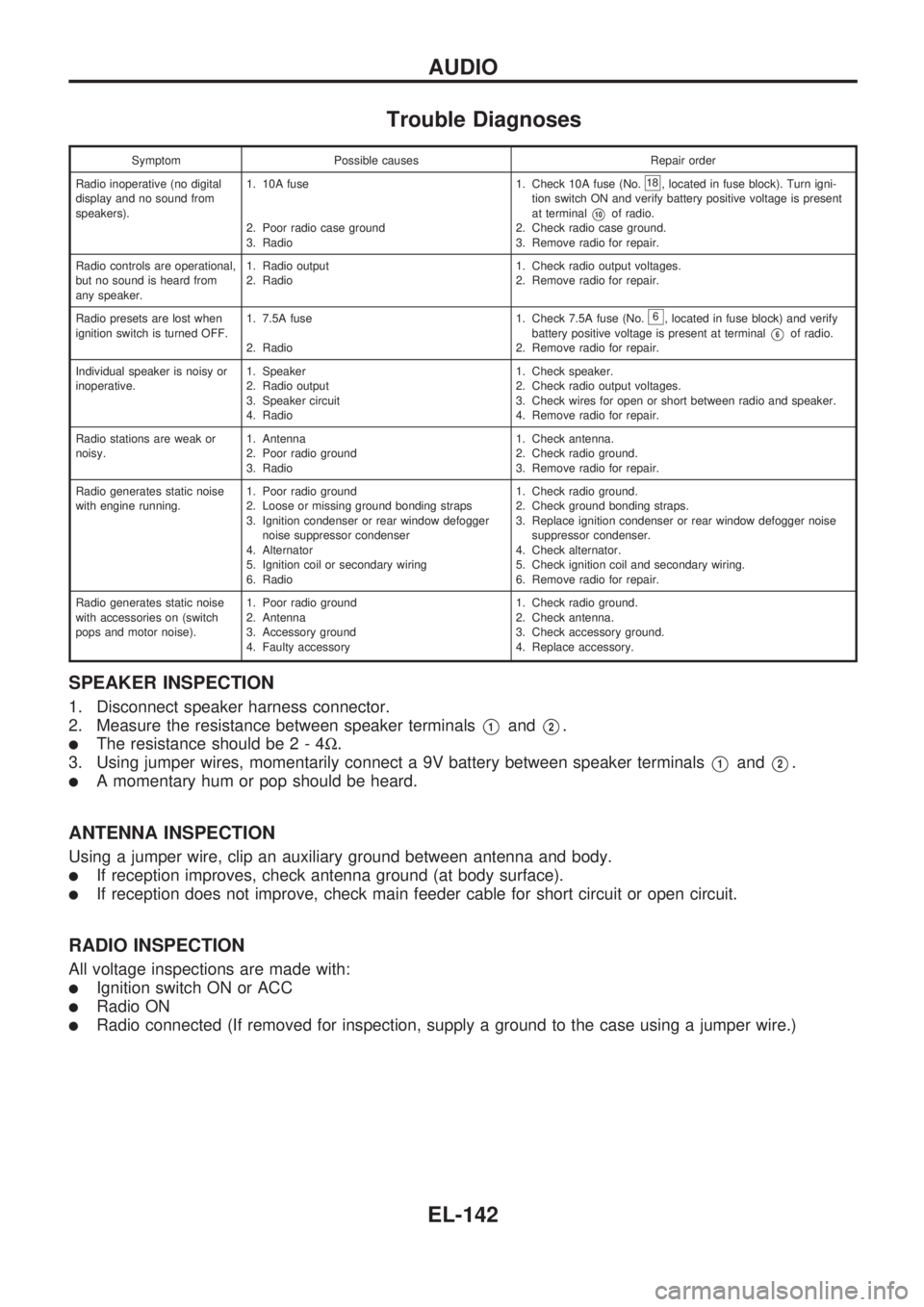
Trouble Diagnoses
Symptom Possible causes Repair order
Radio inoperative (no digital
display and no sound from
speakers).1. 10A fuse
2. Poor radio case ground
3. Radio1. Check 10A fuse (No.
18, located in fuse block). Turn igni-
tion switch ON and verify battery positive voltage is present
at terminal
V10of radio.
2. Check radio case ground.
3. Remove radio for repair.
Radio controls are operational,
but no sound is heard from
any speaker.1. Radio output
2. Radio1. Check radio output voltages.
2. Remove radio for repair.
Radio presets are lost when
ignition switch is turned OFF.1. 7.5A fuse
2. Radio1. Check 7.5A fuse (No.
6, located in fuse block) and verify
battery positive voltage is present at terminal
V6of radio.
2. Remove radio for repair.
Individual speaker is noisy or
inoperative.1. Speaker
2. Radio output
3. Speaker circuit
4. Radio1. Check speaker.
2. Check radio output voltages.
3. Check wires for open or short between radio and speaker.
4. Remove radio for repair.
Radio stations are weak or
noisy.1. Antenna
2. Poor radio ground
3. Radio1. Check antenna.
2. Check radio ground.
3. Remove radio for repair.
Radio generates static noise
with engine running.1. Poor radio ground
2. Loose or missing ground bonding straps
3. Ignition condenser or rear window defogger
noise suppressor condenser
4. Alternator
5. Ignition coil or secondary wiring
6. Radio1. Check radio ground.
2. Check ground bonding straps.
3. Replace ignition condenser or rear window defogger noise
suppressor condenser.
4. Check alternator.
5. Check ignition coil and secondary wiring.
6. Remove radio for repair.
Radio generates static noise
with accessories on (switch
pops and motor noise).1. Poor radio ground
2. Antenna
3. Accessory ground
4. Faulty accessory1. Check radio ground.
2. Check antenna.
3. Check accessory ground.
4. Replace accessory.
SPEAKER INSPECTION
1. Disconnect speaker harness connector.
2. Measure the resistance between speaker terminals
V1andV2.
lThe resistance should be2-4W.
3. Using jumper wires, momentarily connect a 9V battery between speaker terminals
V1andV2.
lA momentary hum or pop should be heard.
ANTENNA INSPECTION
Using a jumper wire, clip an auxiliary ground between antenna and body.
lIf reception improves, check antenna ground (at body surface).
lIf reception does not improve, check main feeder cable for short circuit or open circuit.
RADIO INSPECTION
All voltage inspections are made with:
lIgnition switch ON or ACC
lRadio ON
lRadio connected (If removed for inspection, supply a ground to the case using a jumper wire.)
AUDIO
EL-142
Page 1446 of 1659
Power Antenna
TROUBLE DIAGNOSES
Symptom Possible causes Repair order
Power antenna does not oper-
ate.1. 7.5A fuse
2. Radio signal
3. Grounds
E6andE39
1. Check 7.5A fuse (No.6, located in fuse block). Verify that
battery positive voltage is present at terminal
V1of power
antenna.
2. Turn ignition switch and radio ON. Verify that battery positive
voltage is present at terminal
V3of power antenna.
3. Check groundsE6andE39.
LOCATION OF ANTENNA
ANTENNA ROD REPLACEMENT
Removal
1. Remove antenna nut and antenna base.
2. Withdraw antenna rod while raising it by operating antenna
motor.
SEL339V
SEL240V
SEL341V
AUDIO ANTENNA
EL-148