1998 NISSAN PICK-UP spark plugs
[x] Cancel search: spark plugsPage 202 of 1659

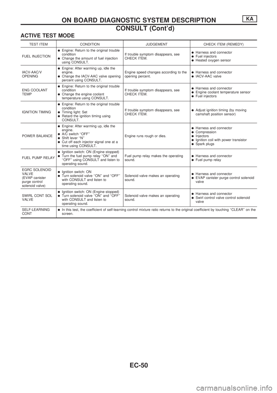
ACTIVE TEST MODE
TEST ITEM CONDITION JUDGEMENT CHECK ITEM (REMEDY)
FUEL INJECTION
lEngine: Return to the original trouble
condition
lChange the amount of fuel injection
using CONSULT.If trouble symptom disappears, see
CHECK ITEM.
lHarness and connectorlFuel injectorslHeated oxygen sensor
IACV-AAC/V
OPENING
lEngine: After warming up, idle the
engine.
lChange the IACV-AAC valve opening
percent using CONSULT.Engine speed changes according to the
opening percent.lHarness and connectorlIACV-AAC valve
ENG COOLANT
TEMP
lEngine: Return to the original trouble
condition
lChange the engine coolant
temperature using CONSULT.If trouble symptom disappears, see
CHECK ITEM.
lHarness and connectorlEngine coolant temperature sensorlFuel injectors
IGNITION TIMING
lEngine: Return to the original trouble
condition
lTiming light: SetlRetard the ignition timing using
CONSULT.If trouble symptom disappears, see
CHECK ITEM.
lAdjust ignition timing (by moving
camshaft position sensor)
POWER BALANCE
lEngine: After warming up, idle the
engine.
lA/C switch ``OFF''lShift lever ``N''lCut off each injector signal one at a
time using CONSULT.Engine runs rough or dies.
lHarness and connectorlCompressionlInjectorslIgnition coil with power transistorlSpark plugs
FUEL PUMP RELAY
lIgnition switch: ON (Engine stopped)lTurn the fuel pump relay ``ON'' and
``OFF'' using CONSULT and listen to
operating sound.Fuel pump relay makes the operating
sound.lHarness and connectorlFuel pump relay
EGRC SOLENOID
VALVE
(EVAP canister
purge control
solenoid valve)
lIgnition switch: ONlTurn solenoid valve ``ON'' and ``OFF''
with CONSULT and listen to
operating sound.Solenoid valve makes an operating
sound.lHarness and connectorlEVAP canister purge control solenoid
valve
SWIRL CONT SOL
VALVE
lIgnition switch: ON (Engine stopped)lTurn solenoid valve ``ON'' and ``OFF''
with CONSULT and listen to
operating sound.Solenoid valve makes an operating
sound.lHarness and connectorlSwirl control valve control solenoid
valve
SELF-LEARNING
CONT
lIn this test, the coefficient of self-learning control mixture ratio returns to the original coefficient by touching ``CLEAR'' on the
screen.
ON BOARD DIAGNOSTIC SYSTEM DESCRIPTIONKA
CONSULT (Cont'd)
EC-50
Page 206 of 1659

Introduction
The engine has an ECM to control major systems such as fuel
control, ignition control, idle air control system, etc. The ECM
accepts input signals from sensors and instantly drives actua-
tors. It is essential that both input and output signals are proper
and stable. At the same time, it is important that there are no
problems such as vacuum leaks, fouled spark plugs, or other
problems with the engine.
It is much more difficult to diagnose a problem that occurs inter-
mittently rather than continuously. Most intermittent problems are
caused by poor electric connections or improper wiring. In this
case, careful checking of suspected circuits may help prevent the
replacement of good parts.
A visual check only may not find the cause of the problems. A
road test with CONSULT or a circuit tester connected should be
performed. Follow the ``Work Flow'' on EC-56.
Before undertaking actual checks, take just a few minutes to talk
with a customer who approaches with a driveability complaint.
The customer can supply good information about such problems,
especially intermittent ones. Find out what symptoms are present
and under what conditions they occur. A ``Diagnostic Worksheet''
like the example on next page should be used.
Start your diagnosis by looking for ``conventional'' problems first.
This will help troubleshoot driveability problems on an electroni-
cally controlled engine vehicle.
Diagnostic Worksheet
There are many operating conditions that lead to the malfunc-
tions of engine components. A good knowledge of such condi-
tions can make troubleshooting faster and more accurate.
In general, each customer may feel differently about a given
problem. It is important to fully understand the symptoms or
conditions for a customer complaint.
Utilize a diagnostic worksheet like the one on next page in order
to organize all the information for troubleshooting.
MEF036D
SEF233G
SEF234G
SEF907L
TROUBLE DIAGNOSIS Ð IntroductionKA
EC-54
Page 655 of 1659

Measurement of Compression Pressure
1. Warm up engine.
2. Turn ignition switch OFF.
3. Release fuel pressure.
Refer to EC section (``Fuel Pressure Release'', ``BASIC SER-
VICE PROCEDURE'').
4. Remove all spark plugs.
5. Disconnect distributor center cable.
6. Attach a compression tester to No. 1 cylinder.
7. Depress accelerator pedal fully to keep throttle valve wide
open.
8. Crank engine and record highest gauge indication.
9. Repeat the measurement on each cylinder.
lAlways use a fully-charged battery to obtain specified
engine speed.
Compression pressure:
kPa (bar, kg/cm
2, psi)/rpm
Standard
1,324 (13.24, 13.5, 192)/300
Minimum
981 (9.8, 10, 142)/300
Difference limit between cylinders
98 (0.98, 1.0, 14)/300
10. If compression in one or more cylinders is low:
a. Pour a small amount of engine oil into cylinders through
spark plug holes.
b. Retest compression.
lIf adding oil helps compression, piston rings may be
worn or damaged. If so, replace piston rings after check-
ing piston.
lIf pressure stays low, a valve may be sticking or seating
improperly. Inspect and repair valve and valve seat.
(Refer to SDS.) If valve or valve seat is damaged
excessively, replace them.
lIf compression stays low in two cylinders that are next
to each other:
a. The cylinder head gasket may be leaking, or
b. Both cylinders may have valve component damage.
Inspect and repair as necessary.
SEM113B
COMPRESSION PRESSUREKA
EM-10
Page 659 of 1659

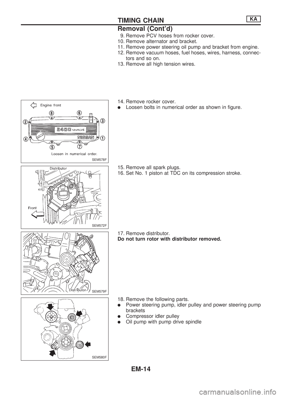
9. Remove PCV hoses from rocker cover.
10. Remove alternator and bracket.
11. Remove power steering oil pump and bracket from engine.
12. Remove vacuum hoses, fuel hoses, wires, harness, connec-
tors and so on.
13. Remove all high tension wires.
14. Remove rocker cover.
lLoosen bolts in numerical order as shown in figure.
15. Remove all spark plugs.
16. Set No. 1 piston at TDC on its compression stroke.
17. Remove distributor.
Do not turn rotor with distributor removed.
18. Remove the following parts.
lPower steering pump, idler pulley and power steering pump
brackets
lCompressor idler pulley
lOil pump with pump drive spindle
SEM578F
SEM572F
SEM579F
SEM580F
TIMING CHAINKA
Removal (Cont'd)
EM-14
Page 665 of 1659

13. Install oil pump and distributor driving spindle with new gas-
ket in front cover.
a. Assemble oil pump and driving spindle, aligning punchmark
on driving spindle with oil hole.
b. Make sure that driving spindle is set as shown in figure.
14. Install distributor.
15. Make sure that No. 1 piston is set at TDC and that distribu-
tor rotor is set at No. 1 cylinder spark position.
16. Install cylinder head outside bolts.
17. Install intake manifold support.
18. Install rubber plugs as follows:
a. Apply liquid gasket to rubber plugs.
lRubber plugs should be replaced with new ones.
lRubber plugs should be installed within 5 minutes of
applying liquid gasket.
SEM395E
SEM574F.SEM574F
SEM572F
SEM596F
SEM931B
TIMING CHAINKA
Installation (Cont'd)
EM-20
Page 972 of 1659

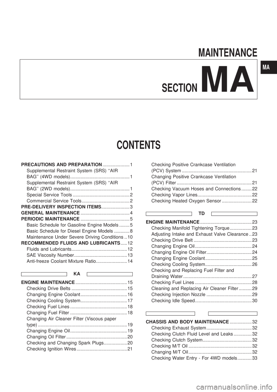
MAINTENANCE
SECTION
MA
CONTENTS
PRECAUTIONS AND PREPARATION..................... 1
Supplemental Restraint System (SRS) ``AIR
BAG'' (4WD models).............................................. 1
Supplemental Restraint System (SRS) ``AIR
BAG'' (2WD models).............................................. 1
Special Service Tools ............................................ 2
Commercial Service Tools ..................................... 2
PRE-DELIVERY INSPECTION ITEMS...................... 3
GENERAL MAINTENANCE...................................... 4
PERIODIC MAINTENANCE...................................... 5
Basic Schedule for Gasoline Engine Models ........ 5
Basic Schedule for Diesel Engine Models ............ 8
Maintenance Under Severe Driving Conditions .. 10
RECOMMENDED FLUIDS AND LUBRICANTS..... 12
Fluids and Lubricants........................................... 12
SAE Viscosity Number......................................... 13
Anti-freeze Coolant Mixture Ratio........................ 14
KA
ENGINE MAINTENANCE........................................ 15
Checking Drive Belts ........................................... 15
Changing Engine Coolant .................................... 16
Checking Cooling System.................................... 17
Checking Fuel Lines ............................................ 18
Changing Fuel Filter ............................................ 18
Changing Air Cleaner Filter (Viscous paper
type) ..................................................................... 19
Changing Engine Oil ............................................ 19
Changing Oil Filter ............................................... 20
Checking and Changing Spark Plugs.................. 20
Checking Ignition Wires ....................................... 21Checking Positive Crankcase Ventilation
(PCV) System ...................................................... 21
Changing Positive Crankcase Ventilation
(PCV) Filter .......................................................... 21
Checking Vacuum Hoses and Connections ........ 22
Checking Vapor Lines.......................................... 22
Checking Heated Oxygen Sensor ....................... 22
TD
ENGINE MAINTENANCE........................................ 23
Checking Manifold Tightening Torque ................. 23
Adjusting Intake and Exhaust Valve Clearance .. 23
Checking Drive Belt ............................................. 23
Changing Engine Oil ............................................ 24
Changing Engine Oil Filter................................... 24
Changing Engine Coolant .................................... 25
Checking Cooling System.................................... 26
Checking and Replacing Fuel Filter and
Draining Water ..................................................... 27
Checking Fuel Lines ............................................ 28
Cleaning and Replacing Air Cleaner Filter .......... 29
Checking Injection Nozzle ................................... 29
Checking Idle Speed............................................ 30
CHASSIS AND BODY MAINTENANCE................. 32
Checking Exhaust System ................................... 32
Checking Clutch Fluid Level and Leaks .............. 32
Checking Clutch System...................................... 32
Checking M/T Oil ................................................. 32
Changing M/T Oil ................................................. 32
Checking Water Entry - For 4WD models ........... 33
MA
Page 978 of 1659

Depending on annual driving distance and engine types, different basic schedules are introduced here.
Please follow the appropriate schedule for the vehicle. Furthermore, according to the weather and atmo-
spheric conditions, varying road surfaces, individual driving habits and vehicle usage, additional or more
frequent maintenance may be required, as shown in ``Maintenance Under Severe Driving Conditions''.
Periodic maintenance beyond the last period shown on the tables requires similar maintenance.
Basic Schedule for Gasoline Engine Models
Engine maintenance for vehicles which drive less than 30,000 km/year (18,000 miles/year)
Abbreviations: R= Replace, I = Inspect and correct or replace as necessary.
MAINTENANCE OPERATIONMAINTENANCE INTERVAL
Reference
page Perform at kilometer (mile) interval or month interval, whichever comes
first.km x 1,000 15 30 45 60 75 90
(Miles x 1,000) (9) (18) (27) (36) (45) (54)
Months 12 24 36 48 60 72
Engine oil (Use API SG or SH oil)*RRRRRRMA-19
Engine oil filter*RRRRRRMA-20
Drive beltsIIIIIIMA-15
Engine anti-freeze coolant (Ethylene glycol base) See NOTE (1) MA-16
Cooling systemIIIIIIMA-17
Air cleaner filter (Viscous paper type)*R MA-19
Fuel linesI I I MA-18
Fuel filter*R MA-18
Vapor linesI I I MA-22
Spark plugs (Conventional type)R R R MA-20
Ignition wiresI I MA-21
Heated oxygen sensor (Exhaust gas sensor)I I I MA-22
PCV filter*R R R MA-21
NOTE: (1) Replace at the first 90,000 km (54,000 miles) or 60 months, then every 60,000 km (36,000 miles) or 48 months,
whichever comes first.
* Maintenance item with ``*'' should be performed more frequently according to ``Maintenance Under Severe Driving Condi-
tions''.
PERIODIC MAINTENANCE
MA-5
Page 980 of 1659

Engine maintenance for vehicles which drive more than 30,000 km/year (18,000 miles/year)
Abbreviations: R= Replace, I = Inspect and correct or replace as necessary.
MAINTENANCE OPERATIONMAINTENANCE INTERVAL
Reference
page
Perform at kilometer (mile) interval.km x 1,000 15 30 45 60 75 90 105 120
(Miles x 1,000) (9) (18) (27) (36) (45) (54) (63) (72)
Engine oil (Use API SG or SH oil)*RRRRRRRRMA-19
Engine oil filter*RRRRRRRRMA-20
Drive beltsIIIIIIIIMA-15
Engine anti-freeze coolant (Ethylene glycol base) See NOTE (1) R MA-16
Cooling systemIIIIMA-17
Air cleaner filter (Viscous paper type)*R R MA-19
Fuel linesI I MA-18
Fuel filter*R MA-18
Vapor linesI I MA-22
Spark plugs (Conventional type)RRRRMA-20
Ignition wiresI MA-21
Heated oxygen sensor (Exhaust gas sensor)I I MA-22
PCV filter*R R MA-21
NOTE: (1) Replace at the first 90,000 km (54,000 miles), then every 60,000 km (36,000 miles).
* Maintenance item with ``*'' should be performed more frequently according to ``Maintenance Under Severe Driving Condi-
tions''.
Chassis and body maintenance for vehicles which drive more than 30,000 km/year (18,000 miles/year)
Abbreviations: R= Replace, I = Inspect and correct or replace as necessary, L = Lubricate, T = Tighten.
MAINTENANCE OPERATIONMAINTENANCE INTERVAL
Reference
page
Perform at kilometer (mile) interval.km x 1,000 15 30 45 60 75 90 105 120
(Miles x 1,000) (9) (18) (27) (36) (45) (54) (63) (72)
Headlamp aimingIIIINOTE (3)
Wheel alignment (If necessary, rotate & balance wheels)IIIIMA-35, NOTE (4)
Brake pads, discs & other brake components*IIIIMA-36
Brake linings, drums & other brake components*IIIIMA-36
Foot brake, parking brake & clutch (For free play, stroke & operation)IIIINOTE (5)
Brake booster vacuum hoses, connections & check valve I I MA-36
Brake & clutch systemsIIIIMA-32, 35
Brake & clutch fluid (For level & leaks)IIIIMA-32, 35
Brake fluid*R R MA-35
Power steering fluid & lines (For level & leaks)IIIIMA-37
Manual steering gear oil (For level & leaks)IIIIMA-38
Air bag system See NOTE (1)NOTE (6)
Manual transmission oil (Inspect for leaks or replace) I I R I MA-32
Transfer fluid and standard differential gear oil (For leaks)* I R I R MA-33, 34
Limited-slip differential (LSD) gear oil (For level and leaks)* I R I R MA-34
Steering gear, linkage, axle, suspension parts & propeller shaft*IIIIMA-37, 33
Greasing point of steering linkage, propeller shaft & sus-
pension*See NOTE (2)LLLLMA-33
Exhaust system*IIIIMA-32
Drive shaft*IIIINOTE (7)
Front wheel bearing grease (2WD models)I I NOTE (8)
Front wheel bearing grease (4WD models)* I R I R NOTE (8)
Free-running hub grease (4WD models)*IIIINOTE (9)
Body mountingsTTTTNOTE (10)
Body corrosionAnnually MA-41
NOTE: (1) Inspect at the first 10 years, and then every 2 years.
(2) The propeller shaft should be re-greased daily if it is immersed in water.
(3) ``Aiming Adjustment'' in EL section
(4) ``Front Wheel Alignment'' in FA section
(5) ``Brake Pedal and Bracket'' in BR section, ``Adjusting Clutch Pedal'' in CL section
(6) ``Maintenance Items'' in RS section
(7) ``FRONT AXLE Ð Drive Shaft'' in FA section
(8) ``Front Wheel Bearing'' in FA section
(9) ``Manual-lock Free-running Hub Ð 4WD'' and ``Auto-lock Free-running Hub Ð 4WD'' in FA section
(10) ``CAB AND REAR BODY'' in BT section
* Maintenance item with ``*'' should be performed more frequently according to ``Maintenance Under Severe Driving Condi-
tions''.
PERIODIC MAINTENANCE
Basic Schedule for Gasoline Engine Models
(Cont'd)
MA-7