Page 140 of 1659
Removal
CAB BODY
lRemove the following parts in engine compartment at least.
(1) Main harness and other wiring harnesses
lDisconnect brake and clutch line in engine compartment.
lRemove the following parts from underbody at least.
(1) Transmission and transfer control levers
(2) Parking brake control lever and cables
(3) Main harness and other wiring harnesses
REAR BODY
lRemove the following parts at least.
(1) Rear combination lamp and license plate lamp harness
(2) Fuel filler tube fixing screws
SBF348C
ABT189
CAB AND REAR BODY
BT-40
Page 270 of 1659
Vehicle Speed Sensor (VSS)
COMPONENT DESCRIPTION
The vehicle speed sensor is installed in the transmission. It con-
tains a pulse generator which provides a vehicle speed signal to
the speedometer. The speedometer then sends a signal to the
ECM.
ECM TERMINALS AND REFERENCE VALUE
Remarks: Specification data are reference values, and are measured between each terminal andV39(ECCS ground) with a voltme-
ter.
TER-
MINAL
NO.WIRE
COLORITEM CONDITIONDATA
(DC voltage)
32 W/L Vehicle speed sensorEngine is running.
Jack up all wheels and run engine at idle in
1st position.Varies from 0 to 5V
SEF068U
SEF089U
TROUBLE DIAGNOSIS FOR NON-DETECTABLE ITEMSKA
EC-118
Page 491 of 1659

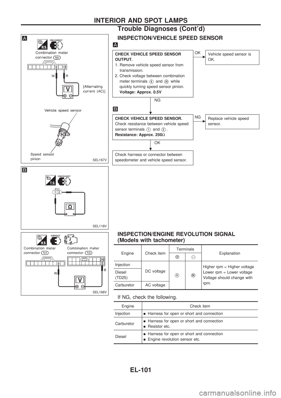
INSPECTION/VEHICLE SPEED SENSOR
CHECK VEHICLE SPEED SENSOR
OUTPUT.
1. Remove vehicle speed sensor from
transmission.
2. Check voltage between combination
meter terminals
V8andV10while
quickly turning speed sensor pinion.
Voltage: Approx. 0.5V
NG
cOK
Vehicle speed sensor is
OK.
CHECK VEHICLE SPEED SENSOR.
Check resistance between vehicle speed
sensor terminals
V1andV2.
Resistance: Approx. 250W
OK
cNG
Replace vehicle speed
sensor.
Check harness or connector between
speedometer and vehicle speed sensor.
INSPECTION/ENGINE REVOLUTION SIGNAL
(Models with tachometer)
Engine Check itemTerminals
ExplanationÅ@
Injection
DC voltage
V9V26
Higher rpm = Higher voltage
Lower rpm = Lower voltage
Voltage should change with
rpm. Diesel
(TD25)
Carburetor AC voltage
If NG, check the following.
Engine Check item
Injection
lHarness for open or short and connection
Carburetor
lHarness for open or short and connection
lResistor etc.
Diesel
lHarness for open or short and connection
lEngine revolution sensor etc.
SEL167V
SEL118V
SEL168V
.
.
INTERIOR AND SPOT LAMPS
Trouble Diagnoses (Cont'd)
EL-101
Page 494 of 1659
FUEL TANK GAUGE UNIT CHECK (With mechanical
fuel pump)
lFor removal, refer to FE section.
Check the resistance between terminals
V1andV2.
Ohmmeter Float position mm (in)
Resistance
value
(W) (+) (þ)60!(13-1/4
Imp gal) tank80!(17-5/8
Imp gal) tank
V1V2
*1 Full 50 (1.97) 247 (9.72) Approx. 4 - 6
*2 1/2 174 (6.85) 130 (5.12) 27 - 35
*3 Empty 277 (10.91) 26 (1.02) 78 - 85
THERMAL TRANSMITTER CHECK
Check the resistance between the terminals of thermal transmit-
ter and body ground.
Water temperature Resistance
60ÉC (140ÉF) Approx. 167 - 211W
100ÉC (212ÉF) Approx. 47 - 53W
VEHICLE SPEED SENSOR SIGNAL CHECK
1. Remove vehicle speed sensor from transmission.
2. Turn vehicle speed sensor pinion quickly and measure volt-
age between terminals
VaandVb.
GEL190-A
MEL424F
SEL378PA
INTERIOR AND SPOT LAMPS
Electrical Components Inspection (Cont'd)
EL-104
Page 681 of 1659
WARNING:
lPosition vehicle on a flat and solid surface.
lPlace chocks at front and back of rear wheels.
lDo not remove engine until exhaust system has com-
pletely cooled off.
Otherwise, you may burn yourself and/or fire may break
out in fuel line.
lBefore disconnecting fuel hose, release fuel pressure.
Refer to EC section (``Fuel Pressure Release'').
lBe sure to hoist engine and transmission in a safe man-
ner.
lFor engines not equipped with engine slingers, attach
proper slingers and bolts described in PARTS CATA-
LOG.
CAUTION:
lWhen lifting engine, be sure to clear surrounding parts.
Take special care near accelerator wire casing, brake
lines and brake master cylinder.
lIn lifting the engine, always use engine slingers in a safe
manner.
lFor 4WD models, apply sealant between engine and
transmission. Refer to MT section (``Removal and Instal-
lation'').
SEM601FA
ENGINE REMOVALKA
EM-36
Page 682 of 1659

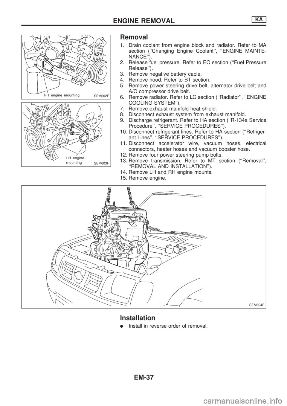
Removal
1. Drain coolant from engine block and radiator. Refer to MA
section (``Changing Engine Coolant'', ``ENGINE MAINTE-
NANCE'').
2. Release fuel pressure. Refer to EC section (``Fuel Pressure
Release'').
3. Remove negative battery cable.
4. Remove hood. Refer to BT section.
5. Remove power steering drive belt, alternator drive belt and
A/C compressor drive belt.
6. Remove radiator. Refer to LC section (``Radiator'', ``ENGINE
COOLING SYSTEM'').
7. Remove exhaust manifold heat shield.
8. Disconnect exhaust system from exhaust manifold.
9. Discharge refrigerant. Refer to HA section (``R-134a Service
Procedure'', ``SERVICE PROCEDURES'').
10. Disconnect refrigerant lines. Refer to HA section (``Refriger-
ant Lines'', ``SERVICE PROCEDURES'').
11. Disconnect accelerator wire, vacuum hoses, electrical
connectors, heater hoses and vacuum booster hose.
12. Remove four power steering pump bolts.
13. Remove transmission. Refer to MT section (``Removal'',
``REMOVAL AND INSTALLATION'').
14. Remove LH and RH engine mounts.
15. Remove engine.
Installation
lInstall in reverse order of removal.
SEM602F
SEM603F
SEM604F
ENGINE REMOVALKA
EM-37
Page 697 of 1659

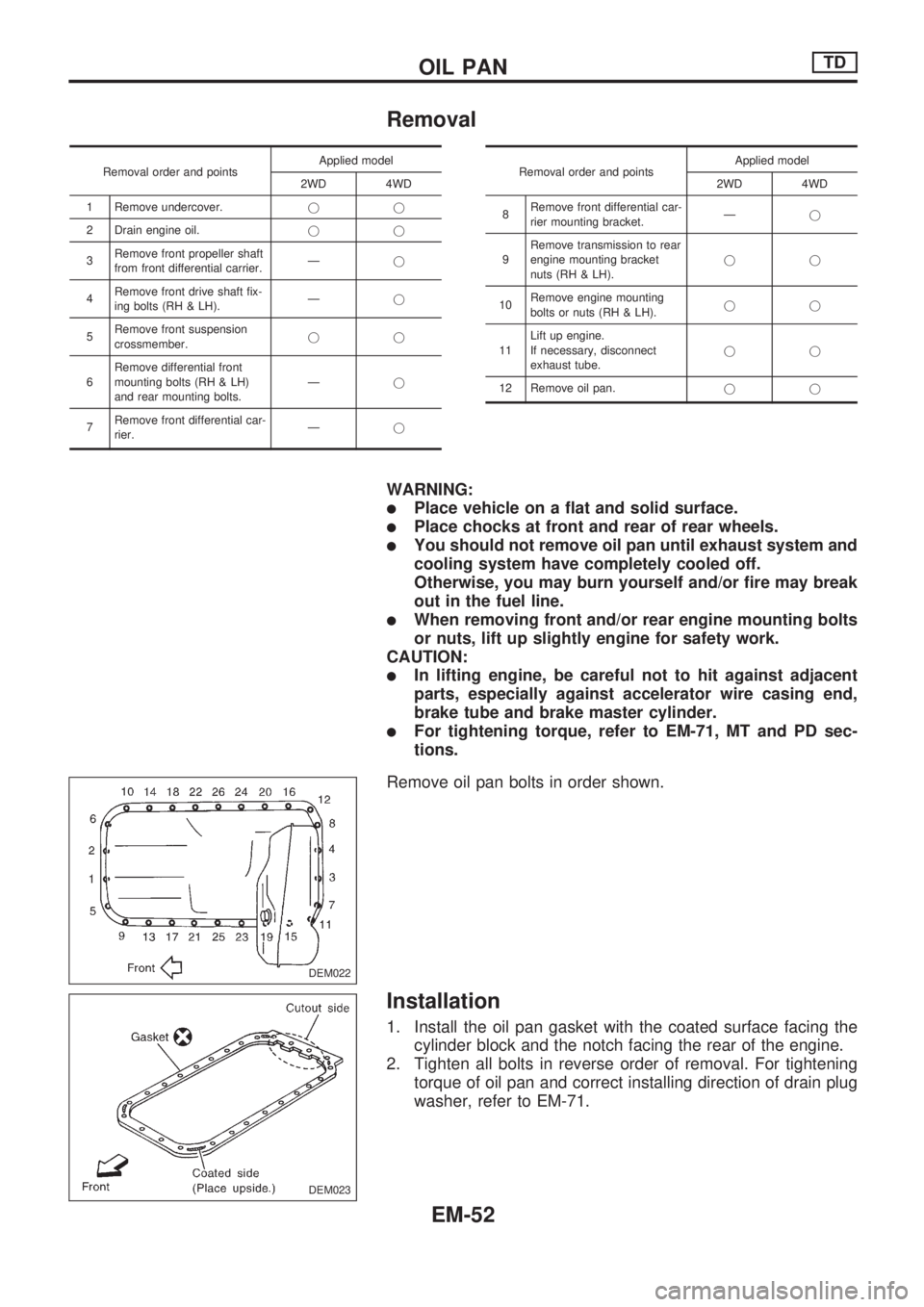
Removal
Removal order and pointsApplied model
2WD 4WD
1 Remove undercover.jj
2 Drain engine oil.jj
3Remove front propeller shaft
from front differential carrier.Ðj
4Remove front drive shaft fix-
ing bolts (RH & LH).Ðj
5Remove front suspension
crossmember.jj
6Remove differential front
mounting bolts (RH & LH)
and rear mounting bolts.Ðj
7Remove front differential car-
rier.ÐjRemoval order and pointsApplied model
2WD 4WD
8Remove front differential car-
rier mounting bracket.Ðj
9Remove transmission to rear
engine mounting bracket
nuts (RH & LH).jj
10Remove engine mounting
bolts or nuts (RH & LH).jj
11Lift up engine.
If necessary, disconnect
exhaust tube.jj
12 Remove oil pan.jj
WARNING:
lPlace vehicle on a flat and solid surface.
lPlace chocks at front and rear of rear wheels.
lYou should not remove oil pan until exhaust system and
cooling system have completely cooled off.
Otherwise, you may burn yourself and/or fire may break
out in the fuel line.
lWhen removing front and/or rear engine mounting bolts
or nuts, lift up slightly engine for safety work.
CAUTION:
lIn lifting engine, be careful not to hit against adjacent
parts, especially against accelerator wire casing end,
brake tube and brake master cylinder.
lFor tightening torque, refer to EM-71, MT and PD sec-
tions.
Remove oil pan bolts in order shown.
Installation
1. Install the oil pan gasket with the coated surface facing the
cylinder block and the notch facing the rear of the engine.
2. Tighten all bolts in reverse order of removal. For tightening
torque of oil pan and correct installing direction of drain plug
washer, refer to EM-71.
DEM022
DEM023
OIL PANTD
EM-52
Page 712 of 1659

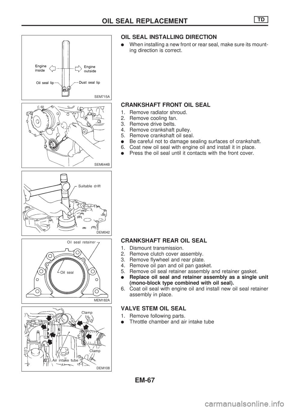
OIL SEAL INSTALLING DIRECTION
lWhen installing a new front or rear seal, make sure its mount-
ing direction is correct.
CRANKSHAFT FRONT OIL SEAL
1. Remove radiator shroud.
2. Remove cooling fan.
3. Remove drive belts.
4. Remove crankshaft pulley.
5. Remove crankshaft oil seal.
lBe careful not to damage sealing surfaces of crankshaft.
6. Coat new oil seal with engine oil and install it in place.
lPress the oil seal until it contacts with the front cover.
CRANKSHAFT REAR OIL SEAL
1. Dismount transmission.
2. Remove clutch cover assembly.
3. Remove flywheel and rear plate.
4. Remove oil pan and oil pan gasket.
5. Remove oil seal retainer assembly and retainer gasket.
lReplace oil seal and retainer assembly as a single unit
(mono-block type combined with oil seal).
6. Coat oil seal with engine oil and install new oil seal retainer
assembly in place.
VALVE STEM OIL SEAL
1. Remove following parts.
lThrottle chamber and air intake tube
SEM715A
SEM644B
DEM042
MEM182A
DEM108
.
OIL SEAL REPLACEMENTTD
EM-67