1998 NISSAN PICK-UP AUX
[x] Cancel search: AUXPage 151 of 1659

TROUBLE DIAGNOSIS FOR POWER SUPPLY.... 75
Main Power Supply and Ground Circuit .............. 75
TROUBLE DIAGNOSIS FOR ``CAMSHAFT
POSI SEN'' (DTC 11).............................................. 82
Camshaft Position Sensor (CMPS) ..................... 82
TROUBLE DIAGNOSIS FOR ``MASS AIR
FLOW SEN'' (DTC 12)............................................ 89
Mass Air Flow Sensor (MAFS) ............................ 89
TROUBLE DIAGNOSIS FOR ``COOLANT TEMP
SEN'' (DTC 13)........................................................ 95
Engine Coolant Temperature Sensor (ECTS) ..... 95
TROUBLE DIAGNOSIS FOR ``IGN SIGNAL-
PRIMARY'' (DTC 21)............................................... 99
Ignition Signal ...................................................... 99
TROUBLE DIAGNOSIS FOR ``OVER HEAT''
(DTC 28)................................................................. 106
Overheat ............................................................ 106
TROUBLE DIAGNOSIS FOR ``INT AIR TEMP
SEN'' (DTC 41)...................................................... 109
Intake Air Temperature Sensor ......................... 109
TROUBLE DIAGNOSIS FOR ``THROTTLE POSI
SEN'' (DTC 43)...................................................... 113
Throttle Position Sensor .................................... 113
TROUBLE DIAGNOSIS FOR
NON-DETECTABLE ITEMS.................................. 118
Vehicle Speed Sensor (VSS) ............................ 118
Heated Oxygen Sensor (HO2S)
- LHD Models - .................................................. 123
Heated Oxygen Sensor Heater
- LHD Models - .................................................. 127
Idle Air Control Valve (IACV) - Auxiliary Air
Control (AAC) Valve .......................................... 131
Neutral Position Switch ...................................... 136
EVAP Canister Purge Control Solenoid Valve .. 140
Injector ............................................................... 144
Start Signal ........................................................ 149
Fuel Pump.......................................................... 151
Power Steering Oil Pressure Switch ................. 157
Swirl Control Valve Control Solenoid Valve ...... 161
IACV-FICD Solenoid Valve ................................ 168
MIL & Data Link Connectors ............................. 173
TD
INJECTION SYSTEM............................................ 176
Fuel System ....................................................... 176
INJECTION PUMP................................................. 178
Inspection ........................................................... 178
Removal ............................................................. 178
Installation and Adjustment................................ 180
Disassembly ....................................................... 183
Load Timer Adjustment...................................... 183
Start Q Adjustment Lever .................................. 184
INJECTION NOZZLE............................................. 186Removal and Installation ................................... 186
Disassembly ....................................................... 186
Inspection ........................................................... 187
Cleaning ............................................................. 187
Assembly............................................................ 189
Test and Adjustment .......................................... 189
FUEL SYSTEM CHECK........................................ 191
Bleeding Fuel System ........................................ 191
Bleeding Fuel Filter ............................................ 192
Checking Priming Pump .................................... 192
Checking Fuel Filter Switch ............................... 192
POSITIVE CRANKCASE VENTILATION.............. 193
Description ......................................................... 193
Inspection ........................................................... 193
QUICK-GLOW SYSTEM........................................ 194
Component Parts Location ................................ 194
Circuit Diagram .................................................. 195
Description ......................................................... 196
Wiring Diagram .................................................. 197
Glow Control Unit Circuit Inspection (For Cold
Areas)................................................................. 203
Glow Control Unit Circuit Inspection (Except
for Cold Areas)................................................... 206
Component Inspection ....................................... 208
EGR SYSTEM........................................................ 210
Component Parts Location ................................ 210
Description ......................................................... 211
Operation ........................................................... 212
Wiring Diagram .................................................. 213
System Inspection.............................................. 217
Component Inspection ....................................... 218
SOLENOID TIMER................................................ 220
Description ......................................................... 220
Operation ........................................................... 220
Wiring Diagram .................................................. 222
Inspection ........................................................... 224
FUEL CUT SYSTEM.............................................. 225
Wiring Diagram .................................................. 225
FUEL HEATER SYSTEM...................................... 226
Description ......................................................... 226
Wiring Diagram .................................................. 227
System Inspection.............................................. 228
Component Inspection ....................................... 228
FAST IDLE CONTROL CIRCUIT.......................... 230
Wiring Diagram .................................................. 230
Electrical Components Inspection ..................... 231
KA
SERVICE DATA AND SPECIFICATIONS (SDS). 232
General Specifications ....................................... 232
Inspection and Adjustment ................................ 232
Page 283 of 1659
Idle Air Control Valve (IACV) Ð Auxiliary Air
Control (AAC) Valve
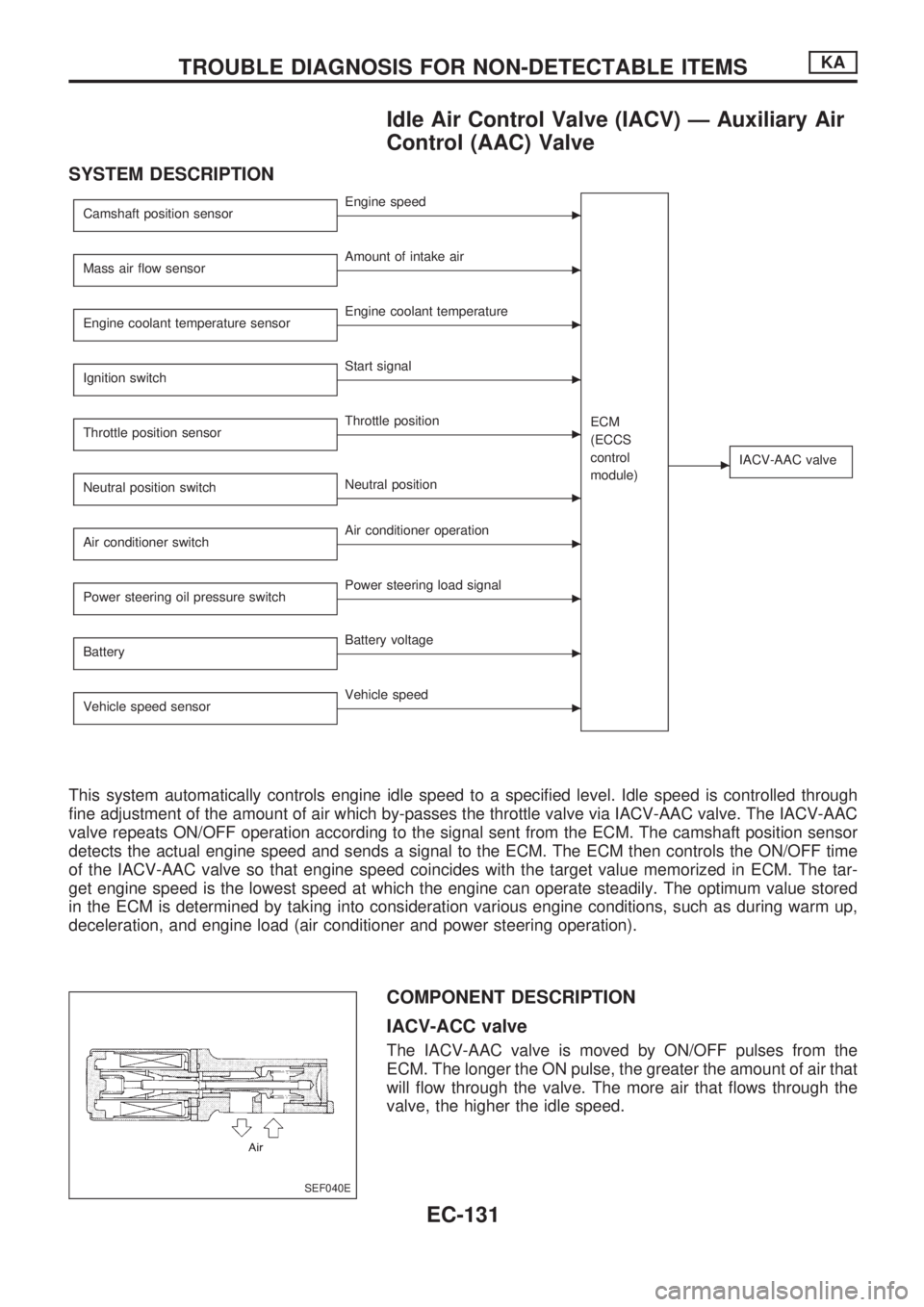
SYSTEM DESCRIPTION
Camshaft position sensorcEngine speed
ECM
(ECCS
control
module)
cIACV-AAC valve
Mass air flow sensorcAmount of intake air
Engine coolant temperature sensor
cEngine coolant temperature
Ignition switch
cStart signal
Throttle position sensor
cThrottle position
Neutral position switch
cNeutral position
Air conditioner switch
cAir conditioner operation
Power steering oil pressure switch
cPower steering load signal
Battery
cBattery voltage
Vehicle speed sensor
cVehicle speed
This system automatically controls engine idle speed to a specified level. Idle speed is controlled through
fine adjustment of the amount of air which by-passes the throttle valve via IACV-AAC valve. The IACV-AAC
valve repeats ON/OFF operation according to the signal sent from the ECM. The camshaft position sensor
detects the actual engine speed and sends a signal to the ECM. The ECM then controls the ON/OFF time
of the IACV-AAC valve so that engine speed coincides with the target value memorized in ECM. The tar-
get engine speed is the lowest speed at which the engine can operate steadily. The optimum value stored
in the ECM is determined by taking into consideration various engine conditions, such as during warm up,
deceleration, and engine load (air conditioner and power steering operation).
COMPONENT DESCRIPTION
IACV-ACC valve
The IACV-AAC valve is moved by ON/OFF pulses from the
ECM. The longer the ON pulse, the greater the amount of air that
will flow through the valve. The more air that flows through the
valve, the higher the idle speed.
SEF040E
TROUBLE DIAGNOSIS FOR NON-DETECTABLE ITEMSKA
EC-131
Page 284 of 1659
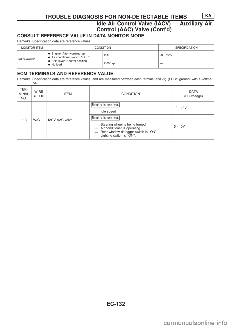
CONSULT REFERENCE VALUE IN DATA MONITOR MODE
Remarks: Specification data are reference values.
MONITOR ITEM CONDITION SPECIFICATION
IACV-AAC/V
lEngine: After warming uplAir conditioner switch: ``OFF''lShift lever: Neutral positionlNo-loadIdle 20 - 40%
2,000 rpm Ð
ECM TERMINALS AND REFERENCE VALUE
Remarks: Specification data are reference values, and are measured between each terminal andV39(ECCS ground) with a voltme-
ter.
TER-
MINAL
NO.WIRE
COLORITEM CONDITIONDATA
(DC voltage)
113 W/G IACV-AAC valveEngine is running.
Idle speed10 - 13V
Engine is running.
Steering wheel is being turned.Air conditioner is operating.Rear window defogger switch is ``ON''.Lighting switch is ``ON''.5 - 10V
TROUBLE DIAGNOSIS FOR NON-DETECTABLE ITEMSKA
Idle Air Control Valve (IACV) Ð Auxiliary Air
Control (AAC) Valve (Cont'd)
EC-132
Page 285 of 1659
HEC355
TROUBLE DIAGNOSIS FOR NON-DETECTABLE ITEMSKA
Idle Air Control Valve (IACV) Ð Auxiliary Air
Control (AAC) Valve (Cont'd)
EC-133
Page 286 of 1659
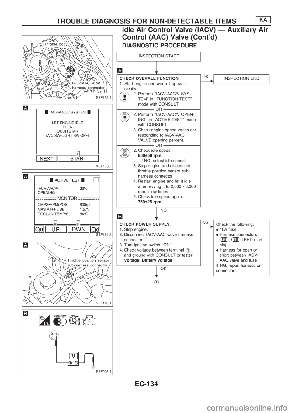
DIAGNOSTIC PROCEDURE
INSPECTION START
CHECK OVERALL FUNCTION.
1. Start engine and warm it up suffi-
ciently.
2. Perform ``IACV-AAC/V SYS-
TEM'' in ``FUNCTION TEST''
mode with CONSULT.
----------------------------------------------------------------------------------------------------------------------------------OR----------------------------------------------------------------------------------------------------------------------------------
2. Perform ``IACV-AAC/V OPEN-
ING'' in ``ACTIVE TEST'' mode
with CONSULT.
3. Check engine speed varies cor-
responding to IACV-AAC
VALVE opening percent.
----------------------------------------------------------------------------------------------------------------------------------OR----------------------------------------------------------------------------------------------------------------------------------
2. Check idle speed.
800 50 rpm
If NG, adjust idle speed.
3. Stop engine and disconnect
throttle position sensor sub-
harness connector.
4. Restart engine and let it idle
after revving it to 2,000 - 3,000
rpm a few times.
5. Check idle speed again.
750 25 rpm
NG
cOK
INSPECTION END
CHECK POWER SUPPLY.
1. Stop engine.
2. Disconnect IACV-AAC valve harness
connector.
3. Turn ignition switch ``ON''.
4. Check voltage between terminal
V3
and ground with CONSULT or tester.
Voltage: Battery voltage
OK
cNG
Check the following.
l10A fuse
lHarness connectorsF54,M48(RHD mod-
els)
lHarness for open or
short between IACV-
AAC valve and fuse
If NG, repair harness or
connectors.
VA
SEF152U
MEF176E
SEF164U
SEF148U
SEF095U
.
.
.
TROUBLE DIAGNOSIS FOR NON-DETECTABLE ITEMSKA
Idle Air Control Valve (IACV) Ð Auxiliary Air
Control (AAC) Valve (Cont'd)
EC-134
Page 287 of 1659
VA
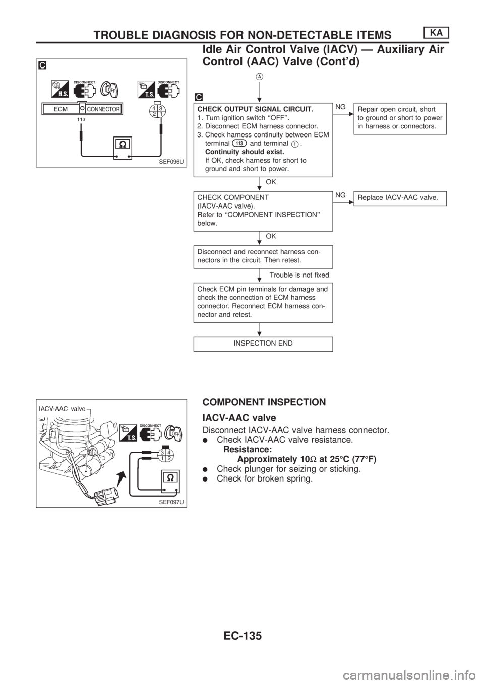
CHECK OUTPUT SIGNAL CIRCUIT.
1. Turn ignition switch ``OFF''.
2. Disconnect ECM harness connector.
3. Check harness continuity between ECM
terminal
113and terminalV1.
Continuity should exist.
If OK, check harness for short to
ground and short to power.
OK
cNG
Repair open circuit, short
to ground or short to power
in harness or connectors.
CHECK COMPONENT
(IACV-AAC valve).
Refer to ``COMPONENT INSPECTION''
below.
OK
cNG
Replace IACV-AAC valve.
Disconnect and reconnect harness con-
nectors in the circuit. Then retest.
Trouble is not fixed.
Check ECM pin terminals for damage and
check the connection of ECM harness
connector. Reconnect ECM harness con-
nector and retest.
INSPECTION END
COMPONENT INSPECTION
IACV-AAC valve
Disconnect IACV-AAC valve harness connector.
lCheck IACV-AAC valve resistance.
Resistance:
Approximately 10Wat 25ÉC (77ÉF)
lCheck plunger for seizing or sticking.
lCheck for broken spring.
SEF096U
SEF097U
.
.
.
.
.
TROUBLE DIAGNOSIS FOR NON-DETECTABLE ITEMSKA
Idle Air Control Valve (IACV) Ð Auxiliary Air
Control (AAC) Valve (Cont'd)
EC-135
Page 532 of 1659
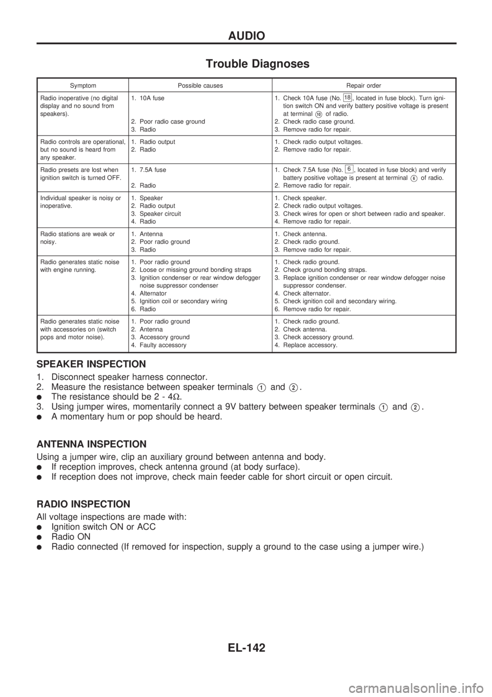
Trouble Diagnoses
Symptom Possible causes Repair order
Radio inoperative (no digital
display and no sound from
speakers).1. 10A fuse
2. Poor radio case ground
3. Radio1. Check 10A fuse (No.
18, located in fuse block). Turn igni-
tion switch ON and verify battery positive voltage is present
at terminal
V10of radio.
2. Check radio case ground.
3. Remove radio for repair.
Radio controls are operational,
but no sound is heard from
any speaker.1. Radio output
2. Radio1. Check radio output voltages.
2. Remove radio for repair.
Radio presets are lost when
ignition switch is turned OFF.1. 7.5A fuse
2. Radio1. Check 7.5A fuse (No.
6, located in fuse block) and verify
battery positive voltage is present at terminal
V6of radio.
2. Remove radio for repair.
Individual speaker is noisy or
inoperative.1. Speaker
2. Radio output
3. Speaker circuit
4. Radio1. Check speaker.
2. Check radio output voltages.
3. Check wires for open or short between radio and speaker.
4. Remove radio for repair.
Radio stations are weak or
noisy.1. Antenna
2. Poor radio ground
3. Radio1. Check antenna.
2. Check radio ground.
3. Remove radio for repair.
Radio generates static noise
with engine running.1. Poor radio ground
2. Loose or missing ground bonding straps
3. Ignition condenser or rear window defogger
noise suppressor condenser
4. Alternator
5. Ignition coil or secondary wiring
6. Radio1. Check radio ground.
2. Check ground bonding straps.
3. Replace ignition condenser or rear window defogger noise
suppressor condenser.
4. Check alternator.
5. Check ignition coil and secondary wiring.
6. Remove radio for repair.
Radio generates static noise
with accessories on (switch
pops and motor noise).1. Poor radio ground
2. Antenna
3. Accessory ground
4. Faulty accessory1. Check radio ground.
2. Check antenna.
3. Check accessory ground.
4. Replace accessory.
SPEAKER INSPECTION
1. Disconnect speaker harness connector.
2. Measure the resistance between speaker terminals
V1andV2.
lThe resistance should be2-4W.
3. Using jumper wires, momentarily connect a 9V battery between speaker terminals
V1andV2.
lA momentary hum or pop should be heard.
ANTENNA INSPECTION
Using a jumper wire, clip an auxiliary ground between antenna and body.
lIf reception improves, check antenna ground (at body surface).
lIf reception does not improve, check main feeder cable for short circuit or open circuit.
RADIO INSPECTION
All voltage inspections are made with:
lIgnition switch ON or ACC
lRadio ON
lRadio connected (If removed for inspection, supply a ground to the case using a jumper wire.)
AUDIO
EL-142
Page 860 of 1659
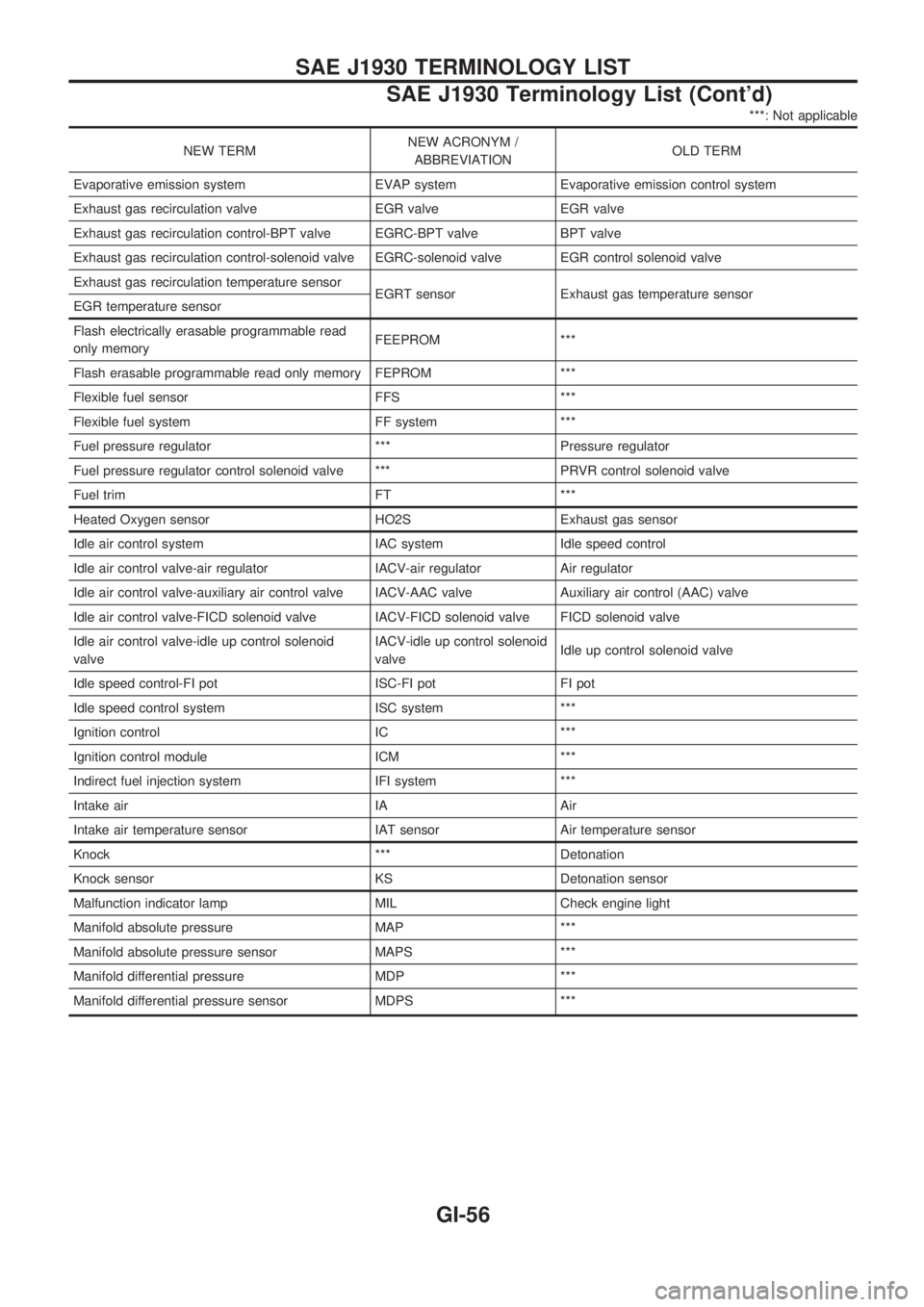
***: Not applicable
NEW TERMNEW ACRONYM /
ABBREVIATIONOLD TERM
Evaporative emission system EVAP system Evaporative emission control system
Exhaust gas recirculation valve EGR valve EGR valve
Exhaust gas recirculation control-BPT valve EGRC-BPT valve BPT valve
Exhaust gas recirculation control-solenoid valve EGRC-solenoid valve EGR control solenoid valve
Exhaust gas recirculation temperature sensor
EGRT sensor Exhaust gas temperature sensor
EGR temperature sensor
Flash electrically erasable programmable read
only memoryFEEPROM ***
Flash erasable programmable read only memory FEPROM ***
Flexible fuel sensor FFS ***
Flexible fuel system FF system ***
Fuel pressure regulator *** Pressure regulator
Fuel pressure regulator control solenoid valve *** PRVR control solenoid valve
Fuel trim FT ***
Heated Oxygen sensor HO2S Exhaust gas sensor
Idle air control system IAC system Idle speed control
Idle air control valve-air regulator IACV-air regulator Air regulator
Idle air control valve-auxiliary air control valve IACV-AAC valve Auxiliary air control (AAC) valve
Idle air control valve-FICD solenoid valve IACV-FICD solenoid valve FICD solenoid valve
Idle air control valve-idle up control solenoid
valveIACV-idle up control solenoid
valveIdle up control solenoid valve
Idle speed control-FI pot ISC-FI pot FI pot
Idle speed control system ISC system ***
Ignition control IC ***
Ignition control module ICM ***
Indirect fuel injection system IFI system ***
Intake air IA Air
Intake air temperature sensor IAT sensor Air temperature sensor
Knock *** Detonation
Knock sensor KS Detonation sensor
Malfunction indicator lamp MIL Check engine light
Manifold absolute pressure MAP ***
Manifold absolute pressure sensor MAPS ***
Manifold differential pressure MDP ***
Manifold differential pressure sensor MDPS ***
SAE J1930 TERMINOLOGY LIST
SAE J1930 Terminology List (Cont'd)
GI-56