1998 NISSAN PICK-UP brake rotor
[x] Cancel search: brake rotorPage 3 of 1659
BRAKE SYSTEM
SECTIONBR
CONTENTS
PRECAUTIONS AND PREPARATION..................... 1
Supplemental Restraint System (SRS) ``AIR
BAG'' (4WD models).............................................. 1
Supplemental Restraint System (SRS) ``AIR
BAG'' (2WD models).............................................. 1
Precautions for Brake System ............................... 1
Special Service Tools ............................................ 2
Commercial Service Tools ..................................... 2
CHECK AND ADJUSTMENT.................................... 3
Checking Brake Fluid Level ................................... 3
Checking Brake Line.............................................. 3
Changing Brake Fluid ............................................ 3
Bleeding Brake System ......................................... 4
BRAKE HYDRAULIC LINE....................................... 5
CONTROL VALVE..................................................... 7
Load Sensing Valve ............................................... 7
BRAKE PEDAL AND BRACKET............................ 10
Removal and Installation ..................................... 10
Inspection ............................................................. 11
Adjustment ........................................................... 11
MASTER CYLINDER............................................... 12
Removal ............................................................... 12
Disassembly ......................................................... 13
Inspection ............................................................. 13
Assembly.............................................................. 13
Installation ............................................................ 14
BRAKE BOOSTER.................................................. 15
On-vehicle Service ............................................... 15
Removal ............................................................... 15
Inspection ............................................................. 15
Installation ............................................................ 16
VACUUM HOSE...................................................... 17
Removal and Installation ..................................... 17Inspection ............................................................. 17
VACUUM PUMP...................................................... 19
Removal and Installation ..................................... 19
Inspection ............................................................. 19
FRONT DISC BRAKE............................................. 21
Pad Replacement ................................................ 21
Removal ............................................................... 22
Disassembly ......................................................... 23
Inspection - Caliper .............................................. 23
Inspection - Rotor ................................................ 23
Assembly.............................................................. 24
Installation ............................................................ 24
Brake Burnishing Procedure ................................ 24
REAR DRUM BRAKE............................................. 26
Removal ............................................................... 27
Inspection - Wheel Cylinder................................. 28
Wheel Cylinder Overhaul ..................................... 28
Inspection - Drum ................................................ 28
Inspection - Lining................................................ 28
Installation ............................................................ 28
PARKING BRAKE CONTROL................................ 30
Removal and Installation ..................................... 31
Inspection ............................................................. 31
Adjustment ........................................................... 31
ANTI-LOCK BRAKE SYSTEM................................ 32
Purpose ................................................................ 32
Operation ............................................................. 32
ABS Hydraulic Circuit .......................................... 32
System Components............................................ 33
System Description .............................................. 33
Removal and Installation ..................................... 35
TROUBLE DIAGNOSES......................................... 38
BR
Page 25 of 1659
Pad Replacement
WARNING:
Clean brake pads with a vacuum dust collector to minimize
the hazard of airborne materials.
CAUTION:
lWhen cylinder body is open, do not depress brake pedal
or caliper piston will pop out.
lBe careful not to damage piston boot or get oil on rotor.
Always replace shims when replacing pads.
lIf shims are rusted or show peeling of the rubber coat,
replace them with new shims.
lIt is not necessary to remove connecting bolt except for
disassembly or replacement of caliper assembly. In this
case, suspend cylinder body with wire so as not to
stretch brake hose.
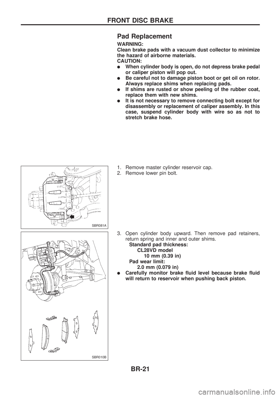
1. Remove master cylinder reservoir cap.
2. Remove lower pin bolt.
3. Open cylinder body upward. Then remove pad retainers,
return spring and inner and outer shims.
Standard pad thickness:
CL28VD model
10 mm (0.39 in)
Pad wear limit:
2.0 mm (0.079 in)
lCarefully monitor brake fluid level because brake fluid
will return to reservoir when pushing back piston.
SBR081A
SBR010B
FRONT DISC BRAKE
BR-21
Page 27 of 1659
Disassembly
WARNING:
Do not place your fingers in front of piston.
CAUTION:
lDo not scratch or score cylinder wall.
lCL28VD type front disc brake uses plastic pistons,
handle them carefully.
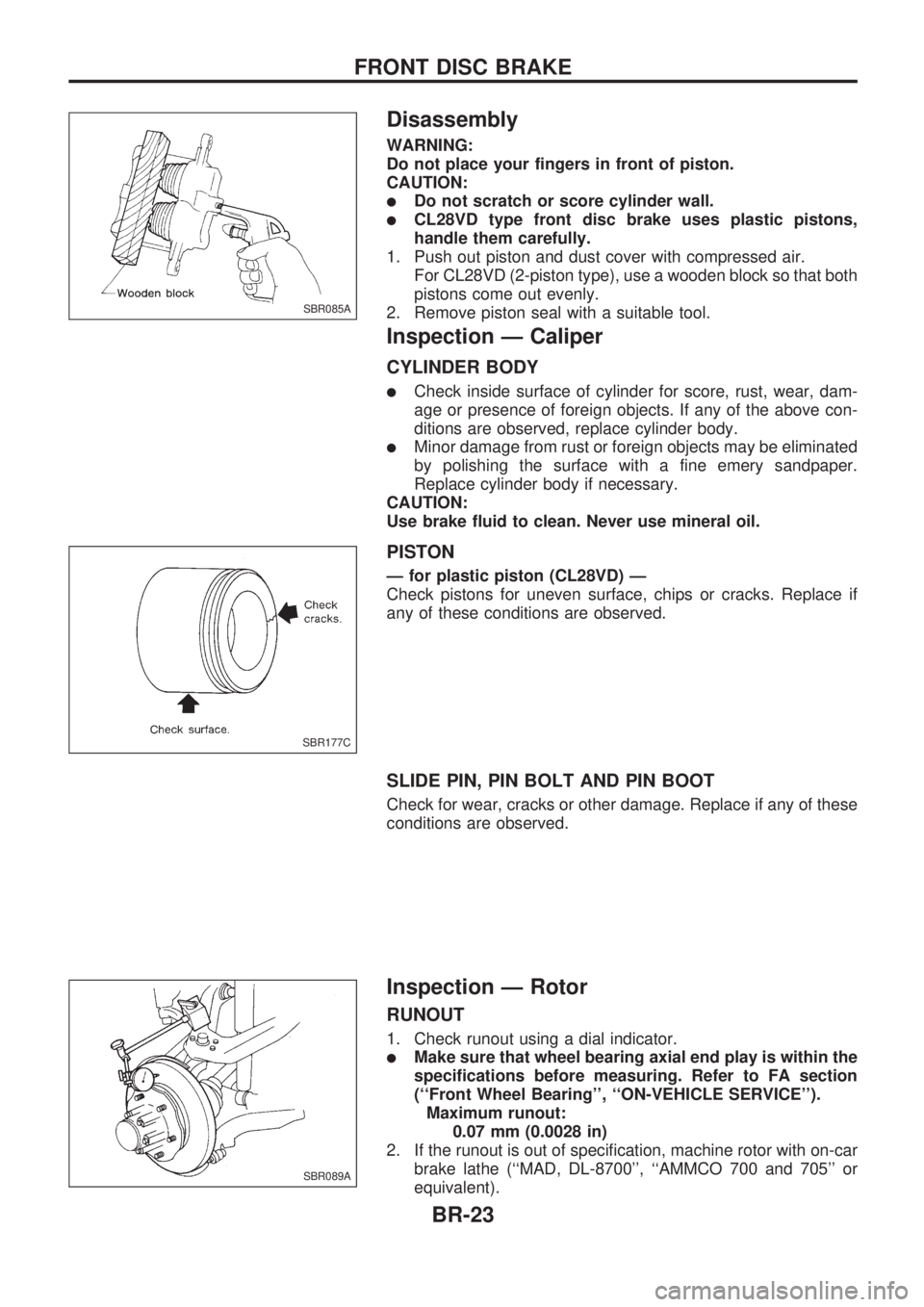
1. Push out piston and dust cover with compressed air.
For CL28VD (2-piston type), use a wooden block so that both
pistons come out evenly.
2. Remove piston seal with a suitable tool.
Inspection Ð Caliper
CYLINDER BODY
lCheck inside surface of cylinder for score, rust, wear, dam-
age or presence of foreign objects. If any of the above con-
ditions are observed, replace cylinder body.
lMinor damage from rust or foreign objects may be eliminated
by polishing the surface with a fine emery sandpaper.
Replace cylinder body if necessary.
CAUTION:
Use brake fluid to clean. Never use mineral oil.
PISTON
Ð for plastic piston (CL28VD) Ð
Check pistons for uneven surface, chips or cracks. Replace if
any of these conditions are observed.
SLIDE PIN, PIN BOLT AND PIN BOOT
Check for wear, cracks or other damage. Replace if any of these
conditions are observed.
Inspection Ð Rotor
RUNOUT
1. Check runout using a dial indicator.
lMake sure that wheel bearing axial end play is within the
specifications before measuring. Refer to FA section
(``Front Wheel Bearing'', ``ON-VEHICLE SERVICE'').
Maximum runout:
0.07 mm (0.0028 in)
2. If the runout is out of specification, machine rotor with on-car
brake lathe (``MAD, DL-8700'', ``AMMCO 700 and 705'' or
equivalent).
SBR085A
SBR177C
SBR089A
FRONT DISC BRAKE
BR-23
Page 28 of 1659
THICKNESS
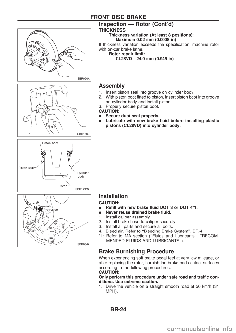
Thickness variation (At least 8 positions):
Maximum 0.02 mm (0.0008 in)
If thickness variation exceeds the specification, machine rotor
with on-car brake lathe.
Rotor repair limit:
CL28VD 24.0 mm (0.945 in)
Assembly
1. Insert piston seal into groove on cylinder body.
2. With piston boot fitted to piston, insert piston boot into groove
on cylinder body and install piston.
3. Properly secure piston boot.
CAUTION:
lSecure dust seal properly.
lLubricate with new brake fluid before installing plastic
pistons (CL28VD) into cylinder body.
Installation
CAUTION:
lRefill with new brake fluid DOT 3 or DOT 4*1.
lNever reuse drained brake fluid.
1. Install caliper assembly.
2. Install brake hose to caliper securely.
3. Install all parts and secure all bolts.
4. Bleed air. Refer to ``Bleeding Brake System'', BR-4.
*1: Refer to MA section (``Fluids and Lubricants'', ``RECOM-
MENDED FLUIDS AND LUBRICANTS'').
Brake Burnishing Procedure
When experiencing soft brake pedal feel at very low mileage, or
after replacing the rotor, burnish the brake pad contact surfaces
according to the following procedures.
CAUTION:
Only perform this procedure under safe road and traffic con-
ditions. Use extreme caution.
1. Drive the vehicle on a straight smooth road at 50 km/h (31
MPH).
SBR090A
SBR178C
SBR179CA
SBR084A
FRONT DISC BRAKE
Inspection Ð Rotor (Cont'd)
BR-24
Page 37 of 1659

System Components
System Description
WHEEL SENSOR
The sensor unit consists of a gear-shaped sensor rotor and a
sensor element. The element contains a bar magnet around
which a coil is wound. The sensor is installed on the back of the
brake rotor and the front of the differential (2WD) or the back of
the rear brake drum (4WD). As the wheel rotates, the sensor
generates a sine-wave pattern. The frequency and voltage
increase(s) as the rotating speed increases.
CONTROL UNIT (built in ABS actuator and electric
unit)
The control unit computes the wheel rotating speed by the sig-
nal current sent from the sensor. Then it supplies a DC current
to the actuator solenoid valve. It also controls ON-OFF operation
of the valve relay and motor relay. If any electrical malfunction
should be detected in the system, the control unit causes the
warning lamp to light up. In this condition, the ABS will be deac-
tivated by the control unit, and the vehicle's brake system reverts
to normal operation. (For control unit layout, refer to ABS
ACTUATOR AND ELECTRIC UNIT, BR-34.)
SBR068E
SBR069E
ANTI-LOCK BRAKE SYSTEM
BR-33
Page 39 of 1659

Removal and Installation
CAUTION:
Be careful not to damage sensor edge and sensor rotor
teeth.
When removing the front wheel hub or rear axle shaft
assembly, disconnect the ABS wheel sensor from the
assembly and move it away.
FRONT WHEEL SENSOR
SBR311E
ANTI-LOCK BRAKE SYSTEM
BR-35
Page 43 of 1659
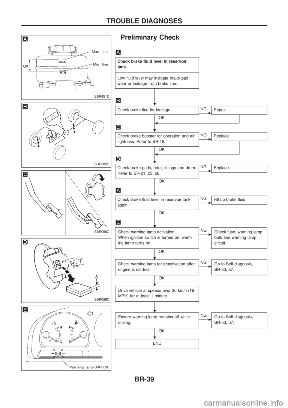
Preliminary Check
Check brake fluid level in reservoir
tank.
-------------------------------------------------------------------------------------------------------------------------------------------------------------------------------------------------------------------------------------------------------------------------------------------------------------
Low fluid level may indicate brake pad
wear or leakage from brake line.
Check brake line for leakage.
OKcNG
Repair.
b
Check brake booster for operation and air
tightness. Refer to BR-15.
OK
cNG
Replace.
b
Check brake pads, rotor, linings and drum.
Refer to BR-21, 23, 28.
OK
cNG
Replace.
Check brake fluid level in reservoir tank
again.
OK
cNG
Fill up brake fluid.
Check warning lamp activation.
When ignition switch is turned on, warn-
ing lamp turns on.
OK
cNG
Check fuse, warning lamp
bulb and warning lamp
circuit.
Check warning lamp for deactivation after
engine is started.
OK
cNG
Go to Self-diagnosis,
BR-53, 57.
Drive vehicle at speeds over 30 km/h (19
MPH) for at least 1 minute.
Ensure warning lamp remains off while
driving.
OK
cNG
Go to Self-diagnosis,
BR-53, 57.
END
SBR451D
SBR389C
SBR058C
SBR059C
SBR069E
.
.
.
.
.
.
.
.
.
TROUBLE DIAGNOSES
BR-39
Page 82 of 1659
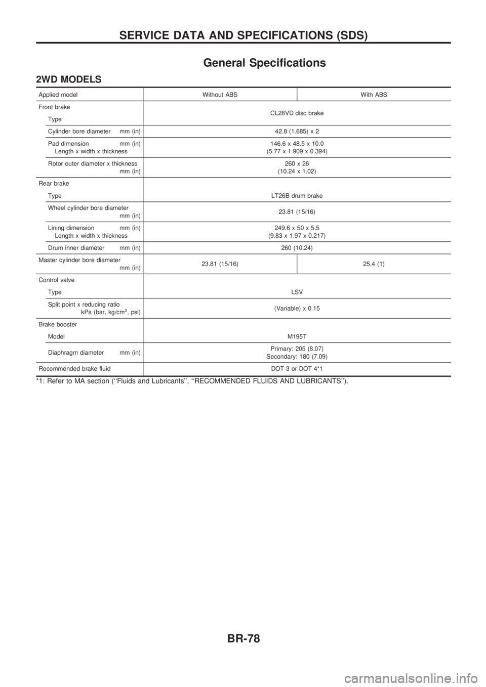
General Specifications
2WD MODELS
Applied model Without ABS With ABS
Front brake
CL28VD disc brake
Type
Cylinder bore diameter mm (in) 42.8 (1.685) x 2
Pad dimension mm (in)
Length x width x thickness146.6 x 48.5 x 10.0
(5.77 x 1.909 x 0.394)
Rotor outer diameter x thickness
mm (in)260x26
(10.24 x 1.02)
Rear brake
TypeLT26B drum brake
Wheel cylinder bore diameter
mm (in)23.81 (15/16)
Lining dimension mm (in)
Length x width x thickness249.6 x 50 x 5.5
(9.83 x 1.97 x 0.217)
Drum inner diameter mm (in) 260 (10.24)
Master cylinder bore diameter
mm (in)23.81 (15/16) 25.4 (1)
Control valve
TypeLSV
Split point x reducing ratio
kPa (bar, kg/cm
2, psi)(Variable) x 0.15
Brake booster
ModelM195T
Diaphragm diameter mm (in)Primary: 205 (8.07)
Secondary: 180 (7.09)
Recommended brake fluid DOT 3 or DOT 4*1
*1: Refer to MA section (``Fluids and Lubricants'', ``RECOMMENDED FLUIDS AND LUBRICANTS'').
SERVICE DATA AND SPECIFICATIONS (SDS)
BR-78