1998 NISSAN PICK-UP check engine light
[x] Cancel search: check engine lightPage 19 of 1659
On-vehicle Service
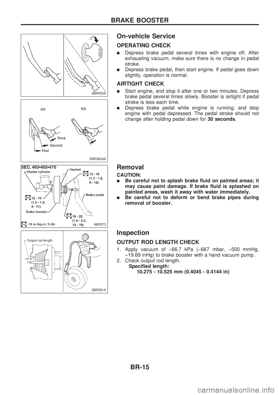
OPERATING CHECK
lDepress brake pedal several times with engine off. After
exhausting vacuum, make sure there is no change in pedal
stroke.
lDepress brake pedal, then start engine. If pedal goes down
slightly, operation is normal.
AIRTIGHT CHECK
lStart engine, and stop it after one or two minutes. Depress
brake pedal several times slowly. Booster is airtight if pedal
stroke is less each time.
lDepress brake pedal while engine is running, and stop
engine with pedal depressed. The pedal stroke should not
change after holding pedal down for30 seconds.
Removal
CAUTION:
lBe careful not to splash brake fluid on painted areas; it
may cause paint damage. If brake fluid is splashed on
painted areas, wash it away with water immediately.
lBe careful not to deform or bend brake pipes during
removal of booster.
Inspection
OUTPUT ROD LENGTH CHECK
1. Apply vacuum of þ66.7 kPa (þ667 mbar, þ500 mmHg,
þ19.69 inHg) to brake booster with a hand vacuum pump.
2. Check output rod length.
Specified length:
10.275 - 10.525 mm (0.4045 - 0.4144 in)
SBR002A
SBR365AA
ABR373
SBR281A
BRAKE BOOSTER
BR-15
Page 97 of 1659
Clutch Disc and Flywheel
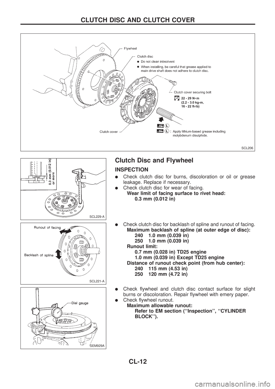
INSPECTION
lCheck clutch disc for burns, discoloration or oil or grease
leakage. Replace if necessary.
lCheck clutch disc for wear of facing.
Wear limit of facing surface to rivet head:
0.3 mm (0.012 in)
lCheck clutch disc for backlash of spline and runout of facing.
Maximum backlash of spline (at outer edge of disc):
240 1.0 mm (0.039 in)
250 1.0 mm (0.039 in)
Runout limit:
0.7 mm (0.028 in) TD25 engine
1.0 mm (0.039 in) Except TD25 engine
Distance of runout check point (from hub center):
240 115 mm (4.53 in)
250 120 mm (4.72 in)
lCheck flywheel and clutch disc contact surface for slight
burns or discoloration. Repair flywheel with emery paper.
lCheck flywheel runout.
Maximum allowable runout:
Refer to EM section (``Inspection'', ``CYLINDER
BLOCK'').
SCL206
SCL229-A
SCL221-A
SEM929A
CLUTCH DISC AND CLUTCH COVER
CL-12
Page 98 of 1659
INSTALLATION
lApply recommended grease to contact surface of spline por-
tion.
Too much lubricant might cause clutch disc facing damage.
Clutch Cover
INSPECTION
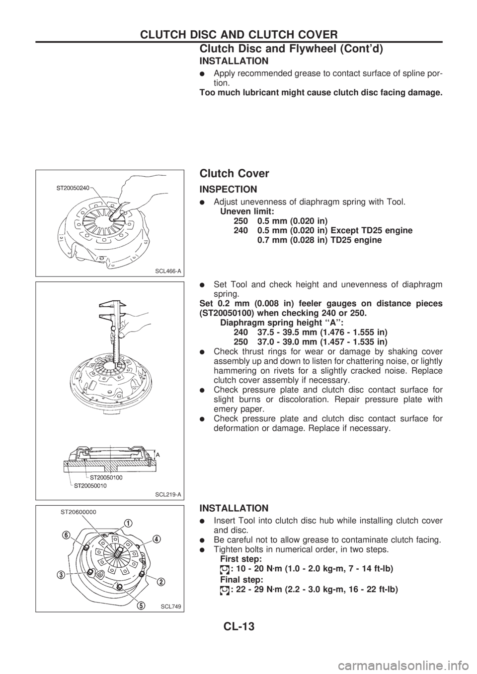
lAdjust unevenness of diaphragm spring with Tool.
Uneven limit:
250 0.5 mm (0.020 in)
240 0.5 mm (0.020 in) Except TD25 engine
0.7 mm (0.028 in) TD25 engine
lSet Tool and check height and unevenness of diaphragm
spring.
Set 0.2 mm (0.008 in) feeler gauges on distance pieces
(ST20050100) when checking 240 or 250.
Diaphragm spring height ``A'':
240 37.5 - 39.5 mm (1.476 - 1.555 in)
250 37.0 - 39.0 mm (1.457 - 1.535 in)
lCheck thrust rings for wear or damage by shaking cover
assembly up and down to listen for chattering noise, or lightly
hammering on rivets for a slightly cracked noise. Replace
clutch cover assembly if necessary.
lCheck pressure plate and clutch disc contact surface for
slight burns or discoloration. Repair pressure plate with
emery paper.
lCheck pressure plate and clutch disc contact surface for
deformation or damage. Replace if necessary.
INSTALLATION
lInsert Tool into clutch disc hub while installing clutch cover
and disc.
lBe careful not to allow grease to contaminate clutch facing.
lTighten bolts in numerical order, in two steps.
First step:
:10-20Nzm (1.0 - 2.0 kg-m,7-14ft-lb)
Final step:
:22-29Nzm (2.2 - 3.0 kg-m, 16 - 22 ft-lb)
SCL466-A
SCL219-A
SCL749
CLUTCH DISC AND CLUTCH COVER
Clutch Disc and Flywheel (Cont'd)
CL-13
Page 178 of 1659

START
Visually check the following:lAir cleaner clogginglHoses and ducts for leakslElectrical connectorslGasketlThrottle valve and throttle position sensor operations
Start engine and warm it up until engine coolant temperature
indicator points to the middle of gauge and ensure that engine
speed is below 1,000 rpm.
Open engine hood and run engine at about 2,000 rpm for about
2 minutes under no-load.
Perform the diagnostic test mode II (Self-diagnostic results).
OKNG
Repair or replace components as necessary.
.
Run engine at about 2,000 rpm for about 2 minutes under no-
load.
Rev engine two or three times under no-load, then run engine for
about 1 minute at idle speed.
1. Select ``IGNITION TIMING ADJ'' in WORK SUPPORT
mode.
2. Touch ``START''.
----------------------------------------------------------------------------------------------------------------------------------------------------------------------------------------------------------------OR----------------------------------------------------------------------------------------------------------------------------------------------------------------------------------------------------------------
1. Stop engine and disconnect throttle position sensor
harness connector.
2. Start engine.
Rev engine (2,000 - 3,000 rpm) 2 or 3 times under no-load and
run engine at idle speed.
Check ignition timing with a timing light.
---------------------------------------------------------------------------------------------------------------------------------------------------------------------------------------------------------------------------------------------------------------------------------------------------------------------------------------------------------------------------------------------------------------------------------------------------------------------
10É 2É BTDC
OK NG
VAVB
SEF146U
SEF247F
SEF051PA
SEF248F
SEF546N
.
.
.
.
.
.
.
.
.
..
BASIC SERVICE PROCEDUREKA
Idle Speed/Ignition Timing/Idle Mixture Ratio
Adjustment (Cont'd)
EC-26
Page 184 of 1659
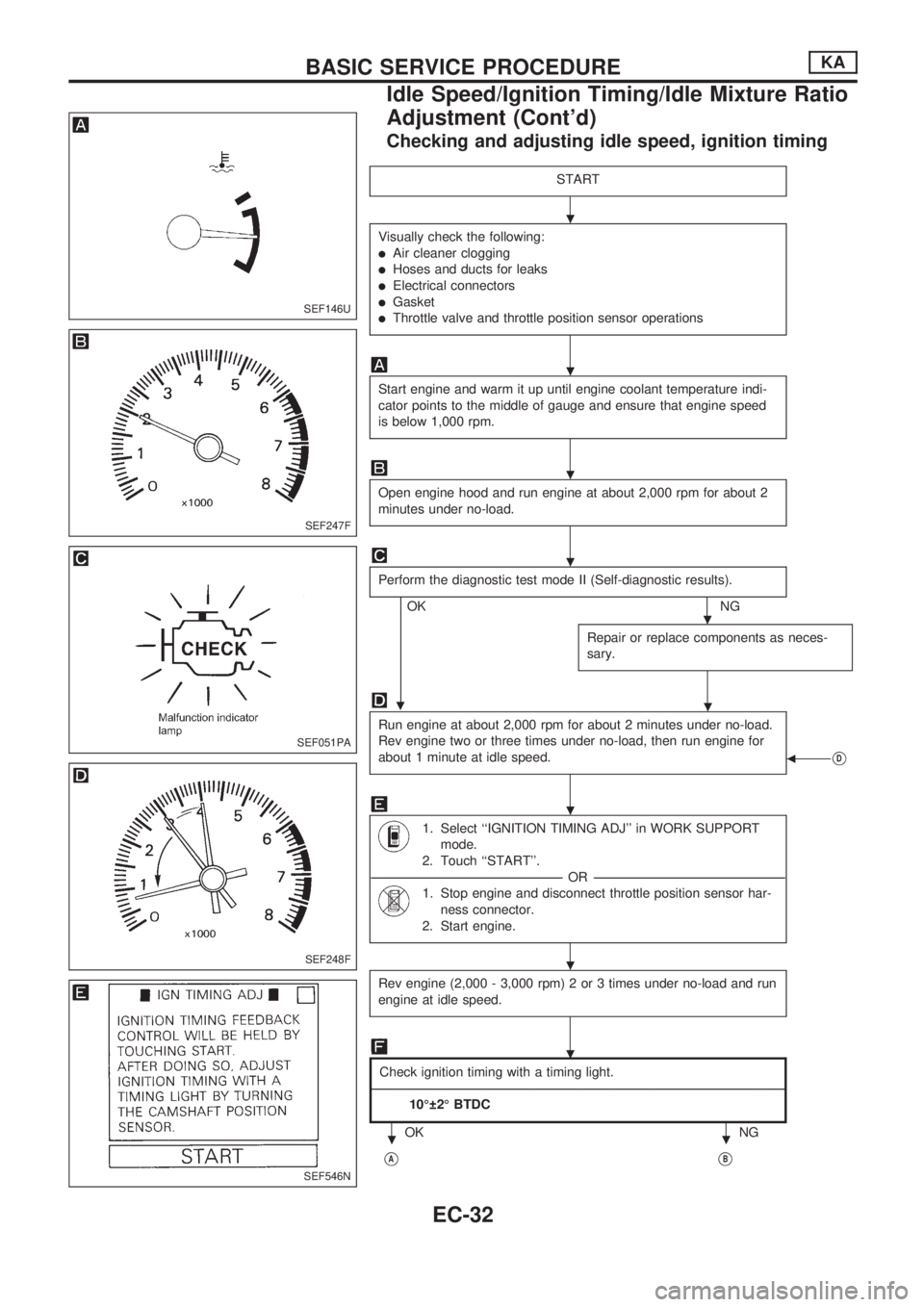
Checking and adjusting idle speed, ignition timing
START
Visually check the following:
lAir cleaner clogging
lHoses and ducts for leaks
lElectrical connectors
lGasket
lThrottle valve and throttle position sensor operations
Start engine and warm it up until engine coolant temperature indi-
cator points to the middle of gauge and ensure that engine speed
is below 1,000 rpm.
Open engine hood and run engine at about 2,000 rpm for about 2
minutes under no-load.
Perform the diagnostic test mode II (Self-diagnostic results).
OKNG
Repair or replace components as neces-
sary.
.
Run engine at about 2,000 rpm for about 2 minutes under no-load.
Rev engine two or three times under no-load, then run engine for
about 1 minute at idle speed.
bVD
1. Select ``IGNITION TIMING ADJ'' in WORK SUPPORT
mode.
2. Touch ``START''.
-----------------------------------------------------------------------------------------------------------------------------------------------------------------------------------------------------------------------OR -----------------------------------------------------------------------------------------------------------------------------------------------------------------------------------------------------------------------
1. Stop engine and disconnect throttle position sensor har-
ness connector.
2. Start engine.
Rev engine (2,000 - 3,000 rpm) 2 or 3 times under no-load and run
engine at idle speed.
Check ignition timing with a timing light.
------------------------------------------------------------------------------------------------------------------------------------------------------------------------------------------------------------------------------------------------------------------------------------------------------------------------------------------------------------------------------------------------------------------------------------------------------------------------------------
10É 2É BTDC
OK NG
VAVB
SEF146U
SEF247F
SEF051PA
SEF248F
SEF546N
.
.
.
.
.
.
.
.
.
..
BASIC SERVICE PROCEDUREKA
Idle Speed/Ignition Timing/Idle Mixture Ratio
Adjustment (Cont'd)
EC-32
Page 190 of 1659
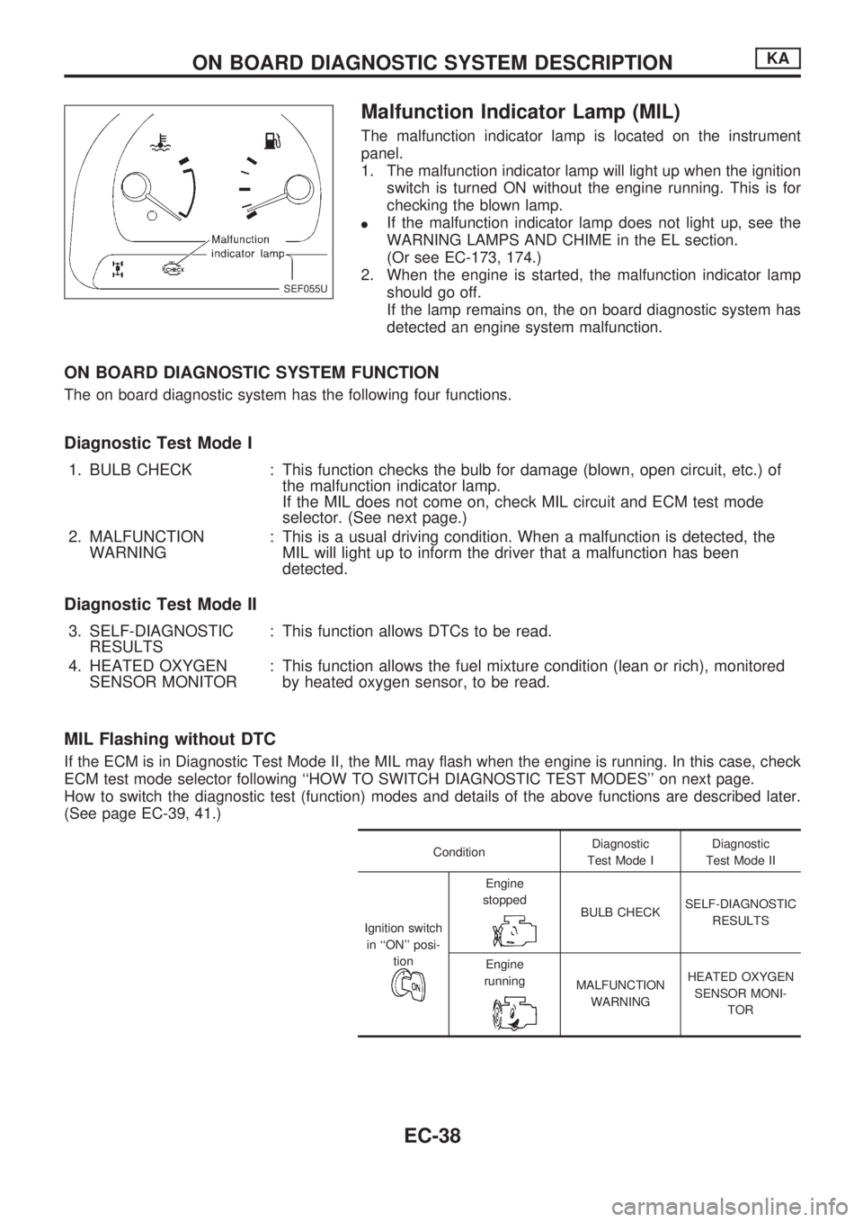
Malfunction Indicator Lamp (MIL)
The malfunction indicator lamp is located on the instrument
panel.
1. The malfunction indicator lamp will light up when the ignition
switch is turned ON without the engine running. This is for
checking the blown lamp.
lIf the malfunction indicator lamp does not light up, see the
WARNING LAMPS AND CHIME in the EL section.
(Or see EC-173, 174.)
2. When the engine is started, the malfunction indicator lamp
should go off.
If the lamp remains on, the on board diagnostic system has
detected an engine system malfunction.
ON BOARD DIAGNOSTIC SYSTEM FUNCTION
The on board diagnostic system has the following four functions.
Diagnostic Test Mode I
1. BULB CHECK : This function checks the bulb for damage (blown, open circuit, etc.) of
the malfunction indicator lamp.
If the MIL does not come on, check MIL circuit and ECM test mode
selector. (See next page.)
2. MALFUNCTION
WARNING: This is a usual driving condition. When a malfunction is detected, the
MIL will light up to inform the driver that a malfunction has been
detected.
Diagnostic Test Mode II
3. SELF-DIAGNOSTIC
RESULTS: This function allows DTCs to be read.
4. HEATED OXYGEN
SENSOR MONITOR: This function allows the fuel mixture condition (lean or rich), monitored
by heated oxygen sensor, to be read.
MIL Flashing without DTC
If the ECM is in Diagnostic Test Mode II, the MIL may flash when the engine is running. In this case, check
ECM test mode selector following ``HOW TO SWITCH DIAGNOSTIC TEST MODES'' on next page.
How to switch the diagnostic test (function) modes and details of the above functions are described later.
(See page EC-39, 41.)
ConditionDiagnostic
Test Mode IDiagnostic
Test Mode II
Ignition switch
in ``ON'' posi-
tion
Engine
stopped
BULB CHECKSELF-DIAGNOSTIC
RESULTS
Engine
running
MALFUNCTION
WARNINGHEATED OXYGEN
SENSOR MONI-
TOR
SEF055U
ON BOARD DIAGNOSTIC SYSTEM DESCRIPTIONKA
EC-38
Page 198 of 1659
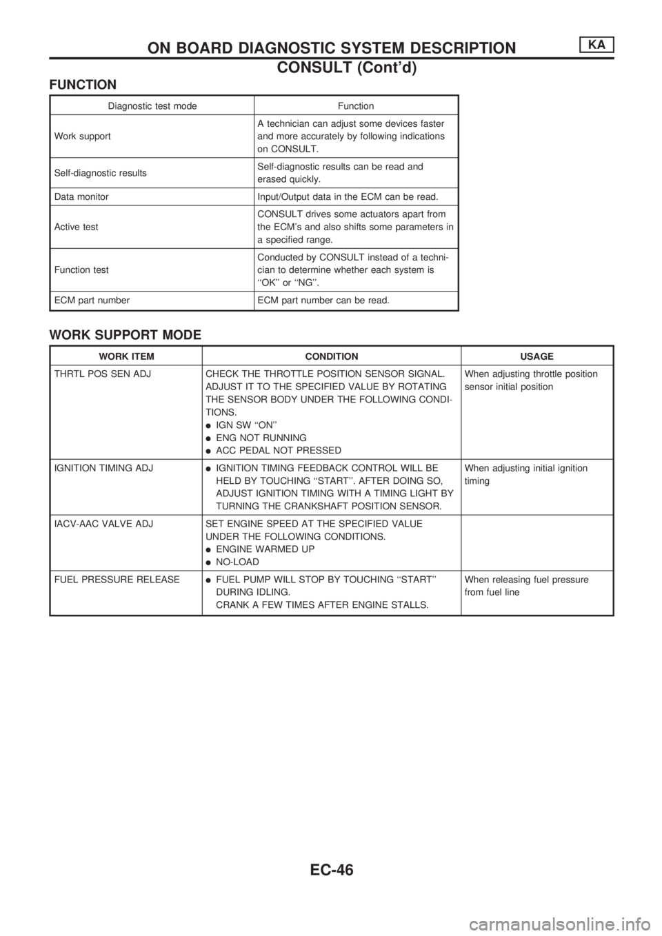
FUNCTION
Diagnostic test mode Function
Work supportA technician can adjust some devices faster
and more accurately by following indications
on CONSULT.
Self-diagnostic resultsSelf-diagnostic results can be read and
erased quickly.
Data monitor Input/Output data in the ECM can be read.
Active testCONSULT drives some actuators apart from
the ECM's and also shifts some parameters in
a specified range.
Function testConducted by CONSULT instead of a techni-
cian to determine whether each system is
``OK'' or ``NG''.
ECM part number ECM part number can be read.
WORK SUPPORT MODE
WORK ITEM CONDITION USAGE
THRTL POS SEN ADJ CHECK THE THROTTLE POSITION SENSOR SIGNAL.
ADJUST IT TO THE SPECIFIED VALUE BY ROTATING
THE SENSOR BODY UNDER THE FOLLOWING CONDI-
TIONS.
lIGN SW ``ON''
lENG NOT RUNNING
lACC PEDAL NOT PRESSEDWhen adjusting throttle position
sensor initial position
IGNITION TIMING ADJ
lIGNITION TIMING FEEDBACK CONTROL WILL BE
HELD BY TOUCHING ``START''. AFTER DOING SO,
ADJUST IGNITION TIMING WITH A TIMING LIGHT BY
TURNING THE CRANKSHAFT POSITION SENSOR.When adjusting initial ignition
timing
IACV-AAC VALVE ADJ SET ENGINE SPEED AT THE SPECIFIED VALUE
UNDER THE FOLLOWING CONDITIONS.
lENGINE WARMED UP
lNO-LOAD
FUEL PRESSURE RELEASE
lFUEL PUMP WILL STOP BY TOUCHING ``START''
DURING IDLING.
CRANK A FEW TIMES AFTER ENGINE STALLS.When releasing fuel pressure
from fuel line
ON BOARD DIAGNOSTIC SYSTEM DESCRIPTIONKA
CONSULT (Cont'd)
EC-46
Page 202 of 1659
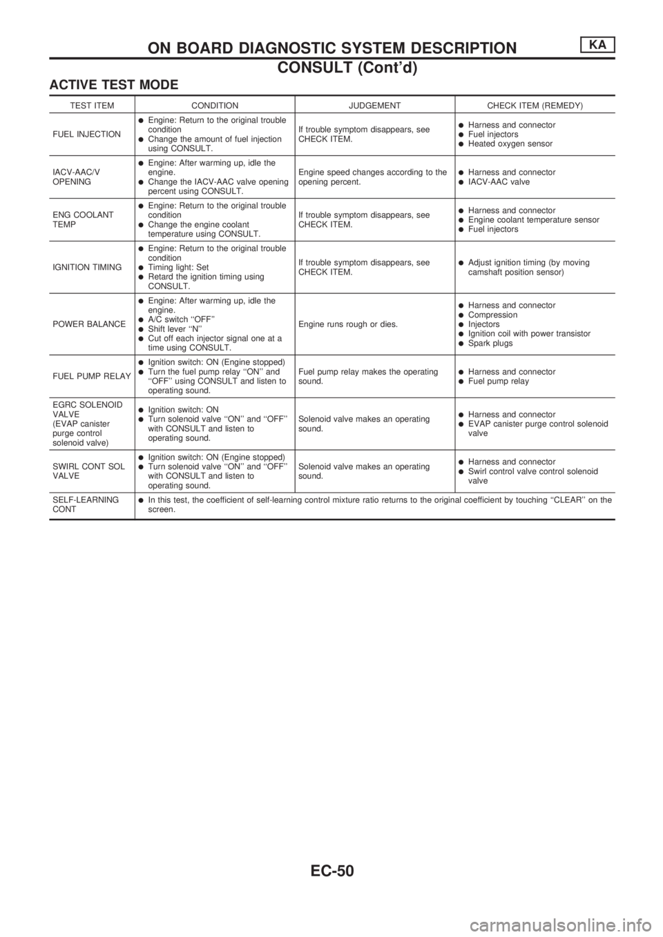
ACTIVE TEST MODE
TEST ITEM CONDITION JUDGEMENT CHECK ITEM (REMEDY)
FUEL INJECTION
lEngine: Return to the original trouble
condition
lChange the amount of fuel injection
using CONSULT.If trouble symptom disappears, see
CHECK ITEM.
lHarness and connectorlFuel injectorslHeated oxygen sensor
IACV-AAC/V
OPENING
lEngine: After warming up, idle the
engine.
lChange the IACV-AAC valve opening
percent using CONSULT.Engine speed changes according to the
opening percent.lHarness and connectorlIACV-AAC valve
ENG COOLANT
TEMP
lEngine: Return to the original trouble
condition
lChange the engine coolant
temperature using CONSULT.If trouble symptom disappears, see
CHECK ITEM.
lHarness and connectorlEngine coolant temperature sensorlFuel injectors
IGNITION TIMING
lEngine: Return to the original trouble
condition
lTiming light: SetlRetard the ignition timing using
CONSULT.If trouble symptom disappears, see
CHECK ITEM.
lAdjust ignition timing (by moving
camshaft position sensor)
POWER BALANCE
lEngine: After warming up, idle the
engine.
lA/C switch ``OFF''lShift lever ``N''lCut off each injector signal one at a
time using CONSULT.Engine runs rough or dies.
lHarness and connectorlCompressionlInjectorslIgnition coil with power transistorlSpark plugs
FUEL PUMP RELAY
lIgnition switch: ON (Engine stopped)lTurn the fuel pump relay ``ON'' and
``OFF'' using CONSULT and listen to
operating sound.Fuel pump relay makes the operating
sound.lHarness and connectorlFuel pump relay
EGRC SOLENOID
VALVE
(EVAP canister
purge control
solenoid valve)
lIgnition switch: ONlTurn solenoid valve ``ON'' and ``OFF''
with CONSULT and listen to
operating sound.Solenoid valve makes an operating
sound.lHarness and connectorlEVAP canister purge control solenoid
valve
SWIRL CONT SOL
VALVE
lIgnition switch: ON (Engine stopped)lTurn solenoid valve ``ON'' and ``OFF''
with CONSULT and listen to
operating sound.Solenoid valve makes an operating
sound.lHarness and connectorlSwirl control valve control solenoid
valve
SELF-LEARNING
CONT
lIn this test, the coefficient of self-learning control mixture ratio returns to the original coefficient by touching ``CLEAR'' on the
screen.
ON BOARD DIAGNOSTIC SYSTEM DESCRIPTIONKA
CONSULT (Cont'd)
EC-50