1998 NISSAN PICK-UP check engine light
[x] Cancel search: check engine lightPage 595 of 1659
Trouble Diagnoses
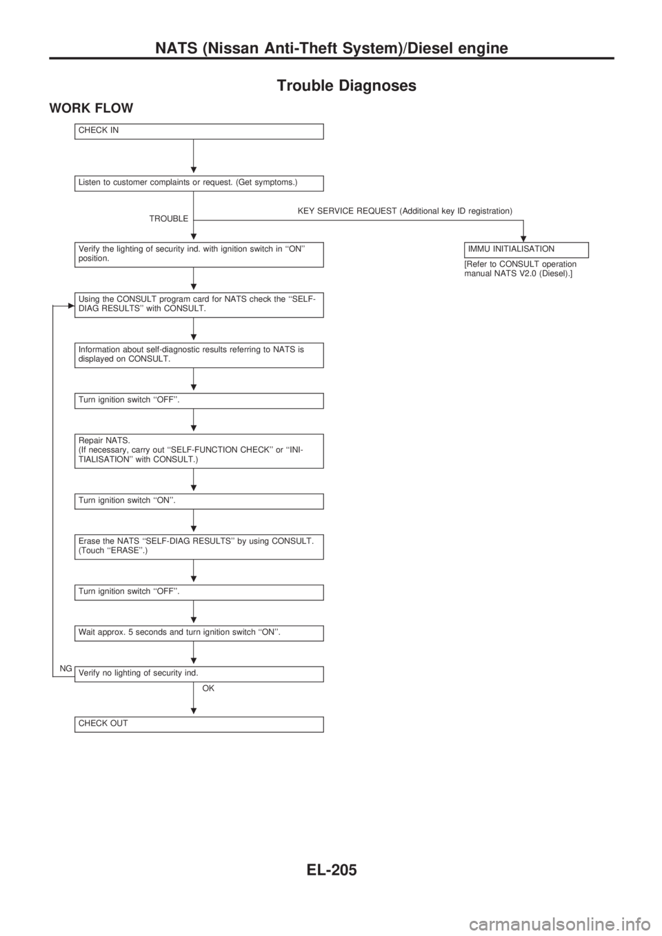
WORK FLOW
CHECK IN
Listen to customer complaints or request. (Get symptoms.)
TROUBLEKEY SERVICE REQUEST (Additional key ID registration)
.Verify the lighting of security ind. with ignition switch in ``ON''
position.IMMU INITIALISATION
[Refer to CONSULT operation
manual NATS V2.0 (Diesel).]
cUsing the CONSULT program card for NATS check the ``SELF-
DIAG RESULTS'' with CONSULT.
Information about self-diagnostic results referring to NATS is
displayed on CONSULT.
Turn ignition switch ``OFF''.
Repair NATS.
(If necessary, carry out ``SELF-FUNCTION CHECK'' or ``INI-
TIALISATION'' with CONSULT.)
Turn ignition switch ``ON''.
Erase the NATS ``SELF-DIAG RESULTS'' by using CONSULT.
(Touch ``ERASE''.)
Turn ignition switch ``OFF''.
Wait approx. 5 seconds and turn ignition switch ``ON''.
NGVerify no lighting of security ind.
OK
CHECK OUT
.
.
.
.
.
.
.
.
.
.
.
.
NATS (Nissan Anti-Theft System)/Diesel engine
EL-205
Page 606 of 1659
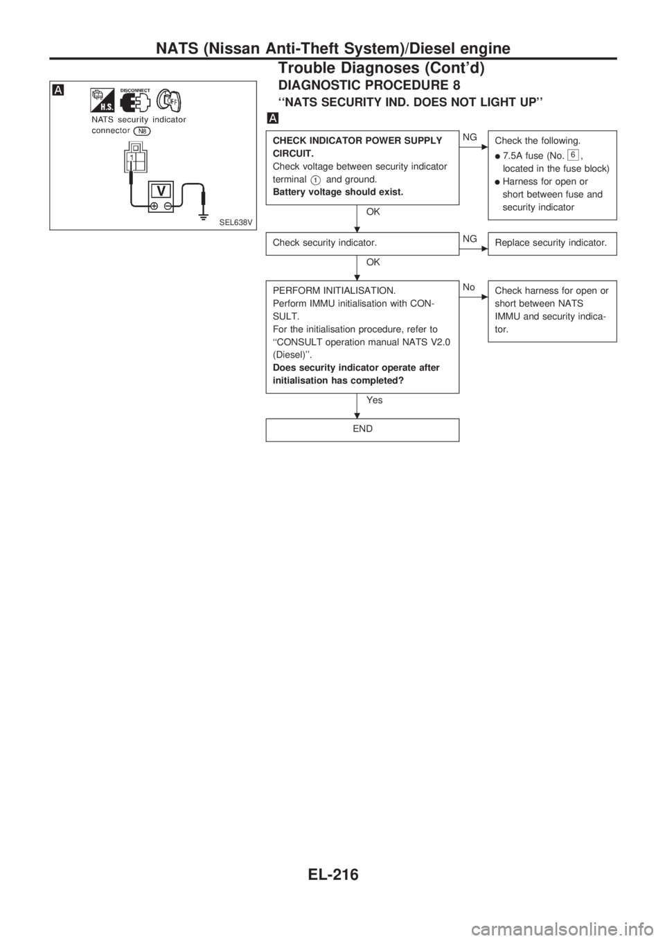
DIAGNOSTIC PROCEDURE 8
``NATS SECURITY IND. DOES NOT LIGHT UP''
CHECK INDICATOR POWER SUPPLY
CIRCUIT.
Check voltage between security indicator
terminal
V1and ground.
Battery voltage should exist.
OK
cNG
Check the following.
l7.5A fuse (No.6,
located in the fuse block)
lHarness for open or
short between fuse and
security indicator
Check security indicator.
OK
cNG
Replace security indicator.
PERFORM INITIALISATION.
Perform IMMU initialisation with CON-
SULT.
For the initialisation procedure, refer to
``CONSULT operation manual NATS V2.0
(Diesel)''.
Does security indicator operate after
initialisation has completed?
Yes
cNo
Check harness for open or
short between NATS
IMMU and security indica-
tor.
END
SEL638V.
.
.
NATS (Nissan Anti-Theft System)/Diesel engine
Trouble Diagnoses (Cont'd)
EL-216
Page 826 of 1659
Incident Simulation Tests
INTRODUCTION
Sometimes the symptom is not present when the vehicle is brought in for service. If possible, re-create the
conditions present at the time of the incident. Doing so may help avoid a No Trouble Found Diagnosis. The
following section illustrates ways to simulate the conditions/environment under which the owner experiences
an electrical incident.
The section is broken into the six following topics:
lVehicle vibration
lHeat sensitive
lFreezing
lWater intrusion
lElectrical load
lCold or hot start up
Get a thorough description of the incident from the customer. It is important for simulating the conditions of
the problem.
VEHICLE VIBRATION
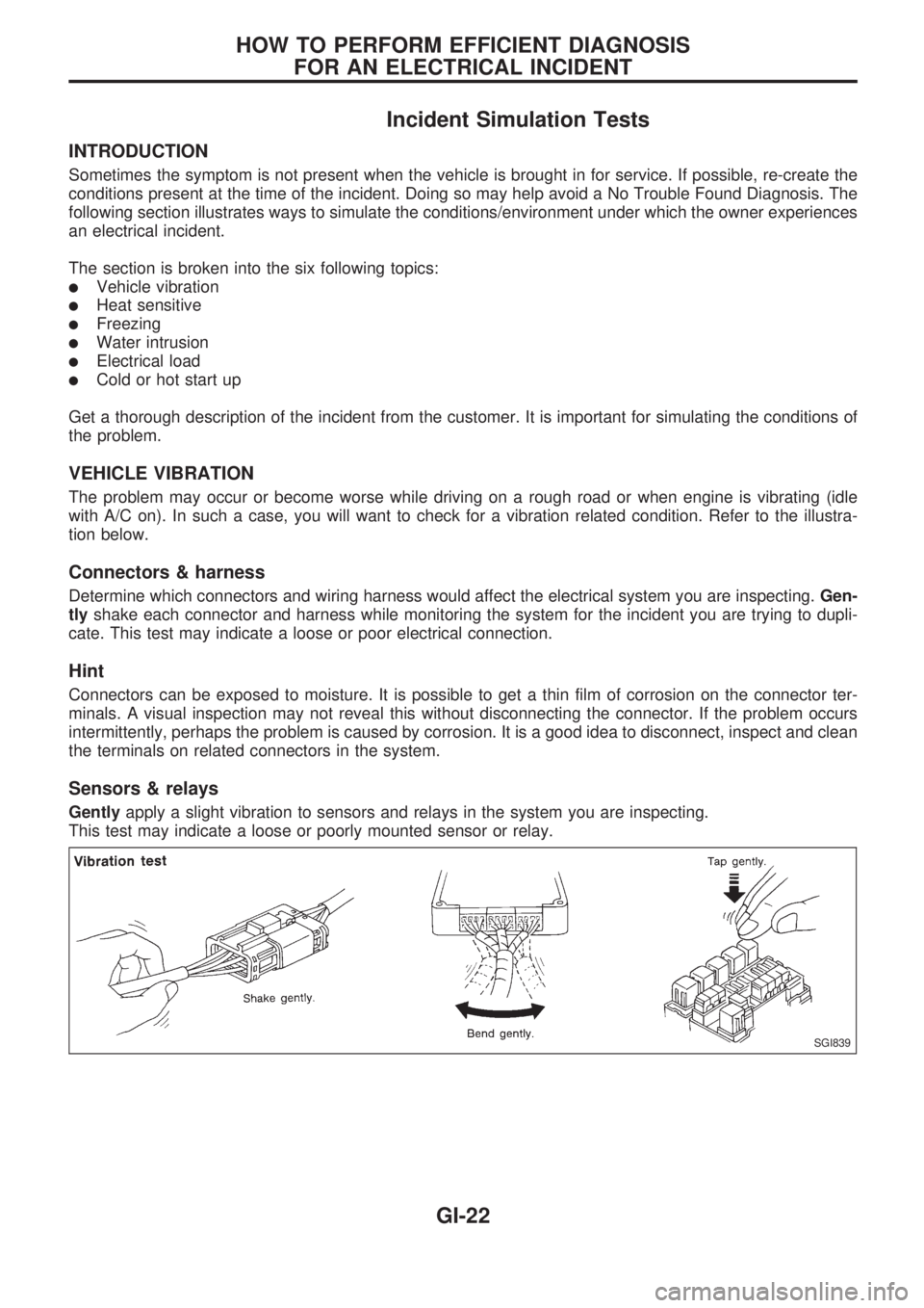
The problem may occur or become worse while driving on a rough road or when engine is vibrating (idle
with A/C on). In such a case, you will want to check for a vibration related condition. Refer to the illustra-
tion below.
Connectors & harness
Determine which connectors and wiring harness would affect the electrical system you are inspecting.Gen-
tlyshake each connector and harness while monitoring the system for the incident you are trying to dupli-
cate. This test may indicate a loose or poor electrical connection.
Hint
Connectors can be exposed to moisture. It is possible to get a thin film of corrosion on the connector ter-
minals. A visual inspection may not reveal this without disconnecting the connector. If the problem occurs
intermittently, perhaps the problem is caused by corrosion. It is a good idea to disconnect, inspect and clean
the terminals on related connectors in the system.
Sensors & relays
Gentlyapply a slight vibration to sensors and relays in the system you are inspecting.
This test may indicate a loose or poorly mounted sensor or relay.
SGI839
HOW TO PERFORM EFFICIENT DIAGNOSIS
FOR AN ELECTRICAL INCIDENT
GI-22
Page 860 of 1659
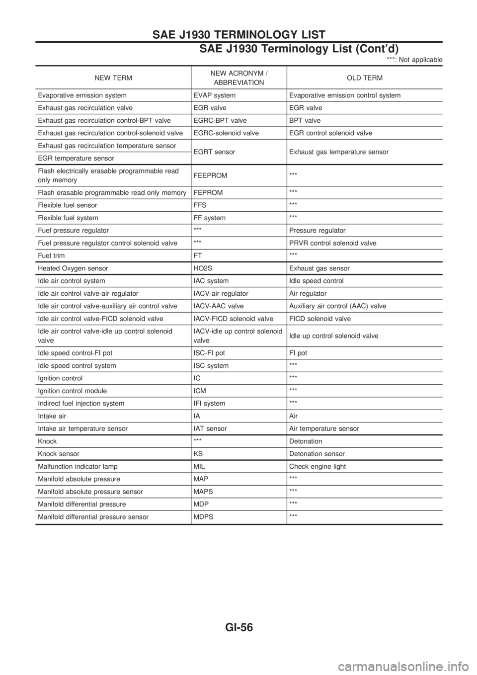
***: Not applicable
NEW TERMNEW ACRONYM /
ABBREVIATIONOLD TERM
Evaporative emission system EVAP system Evaporative emission control system
Exhaust gas recirculation valve EGR valve EGR valve
Exhaust gas recirculation control-BPT valve EGRC-BPT valve BPT valve
Exhaust gas recirculation control-solenoid valve EGRC-solenoid valve EGR control solenoid valve
Exhaust gas recirculation temperature sensor
EGRT sensor Exhaust gas temperature sensor
EGR temperature sensor
Flash electrically erasable programmable read
only memoryFEEPROM ***
Flash erasable programmable read only memory FEPROM ***
Flexible fuel sensor FFS ***
Flexible fuel system FF system ***
Fuel pressure regulator *** Pressure regulator
Fuel pressure regulator control solenoid valve *** PRVR control solenoid valve
Fuel trim FT ***
Heated Oxygen sensor HO2S Exhaust gas sensor
Idle air control system IAC system Idle speed control
Idle air control valve-air regulator IACV-air regulator Air regulator
Idle air control valve-auxiliary air control valve IACV-AAC valve Auxiliary air control (AAC) valve
Idle air control valve-FICD solenoid valve IACV-FICD solenoid valve FICD solenoid valve
Idle air control valve-idle up control solenoid
valveIACV-idle up control solenoid
valveIdle up control solenoid valve
Idle speed control-FI pot ISC-FI pot FI pot
Idle speed control system ISC system ***
Ignition control IC ***
Ignition control module ICM ***
Indirect fuel injection system IFI system ***
Intake air IA Air
Intake air temperature sensor IAT sensor Air temperature sensor
Knock *** Detonation
Knock sensor KS Detonation sensor
Malfunction indicator lamp MIL Check engine light
Manifold absolute pressure MAP ***
Manifold absolute pressure sensor MAPS ***
Manifold differential pressure MDP ***
Manifold differential pressure sensor MDPS ***
SAE J1930 TERMINOLOGY LIST
SAE J1930 Terminology List (Cont'd)
GI-56
Page 864 of 1659
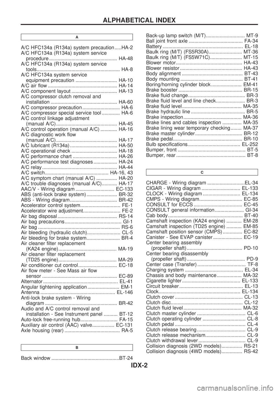
A
A/C HFC134a (R134a) system precaution .....HA-2
A/C HFC134a (R134a) system service
procedure ................................................. HA-48
A/C HFC134a (R134a) system service
tools............................................................ HA-8
A/C HFC134a system service
equipment precaution .............................. HA-10
A/C air flow .................................................. HA-14
A/C component layout ................................. HA-13
A/C compressor clutch removal and
installation ................................................ HA-60
A/C compressor precaution ........................... HA-6
A/C compressor special service tool ............. HA-6
A/C control linkage adjustment
(manual A/C) ............................................ HA-45
A/C control operation (manual A/C) ............ HA-16
A/C diagnostic work flow
(manual A/C) ............................................ HA-17
A/C lubricant (R134a) .................................. HA-50
A/C operational check ................................. HA-18
A/C performance chart ................................ HA-26
A/C performance test diagnoses ................. HA-24
A/C relay ...................................................... HA-44
A/C switch.............................................. HA-16, 43
A/C symptom chart (manual A/C) ............... HA-20
A/C trouble diagnoses (manual A/C)........... HA-17
AAC/V - Wiring diagram ............................ EC-133
ABS (anti-lock brake system) ...................... BR-32
ABS - Wiring diagram .................................. BR-42
Accelerator control system............................. FE-1
Accelerator wire adjustment........................... FE-2
Air bag disposal ........................................... RS-14
Air bag precautions ......................................... GI-1
Air bag ........................................................... RS-6
Air bleeding (hydraulic clutch)........................ CL-5
Air bleeding for brake system........................ BR-4
Air cleaner filter replacement
(KA24 engine).......................................... MA-19
Air cleaner filter replacement
(TD25 engine).......................................... MA-29
Air conditioner cut control ............................ EC-18
Air flow meter - See Mass air flow
sensor ...................................................... EC-89
Alternator ...................................................... EL-41
Angular tightening application ....................... EM-1
Antenna ...................................................... EL-146
Anti-lock brake system - Wiring
diagram .................................................... BR-42
Audio and A/C control removal and
installation - See Instrument panel .......... BT-12
Auto-lock free-running hub........................... FA-15
Auxiliary air control (AAC) valve................ EC-131
Axle housing (rear) ........................................ RA-5
B
Back window .................................................BT-24Back-up lamp switch (M/T)............................ MT-9
Ball joint front axle ....................................... FA-34
Battery .......................................................... EL-18
Baulk ring (M/T) (FS5R30A)........................ MT-36
Baulk ring (M/T) (FS5W71C)....................... MT-15
Blower motor................................................ HA-43
Blower resistor ............................................. HA-43
Body alignment ............................................ BT-43
Body mounting ............................................. BT-41
Boring/horning cylinder block ...................... EM-41
Brake booster .............................................. BR-15
Brake fluid change ......................................... BR-3
Brake fluid level and line check..................... BR-3
Brake fluid level ........................................... MA-35
Brake hydraulic line ....................................... BR-5
Brake inspection .......................................... MA-36
Brake lines and cables inspection .............. MA-35
Brake lining wear temporary checking ........ MA-37
Brake master cylinder .................................. BR-12
Brake pedal.................................................. BR-10
Bulb specifications...................................... EL-252
Bumper, front ................................................. BT-5
Bumper, rear .................................................. BT-8
C
CHARGE - Wiring diagram ...........................EL-34
CIGAR - Wiring diagram ............................ EL-133
CLOCK - Wiring diagram ........................... EL-134
CMPS - Wiring diagram............................... EC-85
CONSULT for ECCS ................................... EC-45
CONSULT general information ..................... GI-34
Cab body ...................................................... BT-40
Camshaft inspection (KA24 engine) ........... EM-28
Camshaft inspection (TD25 engine) ........... EM-85
Camshaft position sensor (CMPS) .............. EC-82
Canister - See EVAP canister ..................... EC-19
Center bearing assembly
(propeller shaft) ........................................ PD-10
Center bearing disassembly
(propeller shaft) .......................................... PD-9
Center case (Transfer) ................................... TF-8
Charging system .......................................... EL-34
Chassis and body maintenance .................. MA-32
Cigarette lighter .......................................... EL-133
Circuit breaker .............................................. EL-13
Clock........................................................... EL-134
Clutch cover ................................................. CL-13
Clutch disc.................................................... CL-12
Clutch fluid level .......................................... MA-32
Clutch master cylinder ................................... CL-6
Clutch operating cylinder ............................... CL-8
Clutch pedal ................................................... CL-4
Clutch release bearing ................................... CL-9
Clutch release mechanism............................. CL-9
Clutch withdrawal lever .................................. CL-9
Collision diagnosis (2WD models)............... RS-21
Collision diagnosis (4WD models)............... RS-42
ALPHABETICAL INDEX
IDX-2
Page 889 of 1659
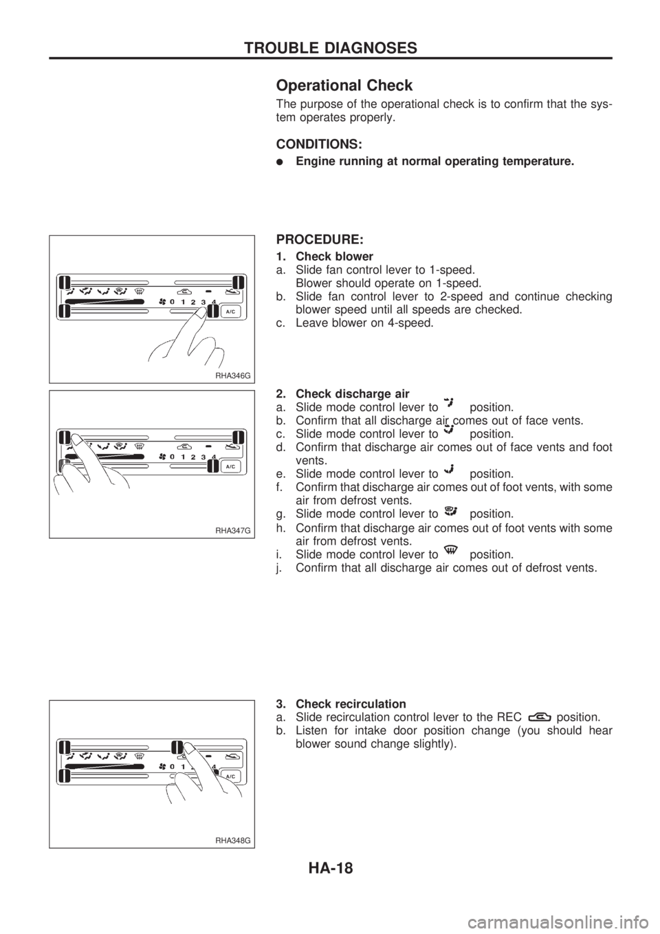
Operational Check
The purpose of the operational check is to confirm that the sys-
tem operates properly.
CONDITIONS:
lEngine running at normal operating temperature.
PROCEDURE:
1. Check blower
a. Slide fan control lever to 1-speed.
Blower should operate on 1-speed.
b. Slide fan control lever to 2-speed and continue checking
blower speed until all speeds are checked.
c. Leave blower on 4-speed.
2. Check discharge air
a. Slide mode control lever to
position.
b. Confirm that all discharge air comes out of face vents.
c. Slide mode control lever to
position.
d. Confirm that discharge air comes out of face vents and foot
vents.
e. Slide mode control lever to
position.
f. Confirm that discharge air comes out of foot vents, with some
air from defrost vents.
g. Slide mode control lever to
position.
h. Confirm that discharge air comes out of foot vents with some
air from defrost vents.
i. Slide mode control lever to
position.
j. Confirm that all discharge air comes out of defrost vents.
3. Check recirculation
a. Slide recirculation control lever to the REC
position.
b. Listen for intake door position change (you should hear
blower sound change slightly).
RHA346G
RHA347G
RHA348G
TROUBLE DIAGNOSES
HA-18
Page 976 of 1659
Shown below are Pre-delivery Inspection Items required for the new vehicle. It is recommended that
necessary items other than those listed here be added, paying due regard to the conditions in each
country.
Perform applicable items on each model. Consult text of this section for specifications.
UNDER HOOD Ð engine off
hRadiator coolant level and coolant hose con-
nections for leaks
hBattery fluid level, specific gravity and condi-
tions of battery terminals
hDrive belts tension
hFuel filter for water or dusts, and fuel lines and
connections for leaks
hEngine oil level and oil leaks
hClutch and brake reservoir fluid level and fluid
lines for leaks
hWindshield and rear window washer and head-
lamp cleaner reservoir fluid level
hPower steering reservoir fluid level and hose
connections for leaks
ON INSIDE AND OUTSIDE
hRemove front spring/strut spacer (If applicable)
hOperation of all instruments, gauges, lights and
accessories
hOperation of horn(s), wiper and washer
hSteering lock for operation
hCheck air conditioner for gas leaks
hFront and rear seats, and seat belts for opera-
tion
hAll moldings, trims and fittings for fit and align-
ment
hAll windows for operation and alignment
hHood, trunk lid, door panels for fit and align-
ment
hLatches, keys and locks for operation
hWeatherstrips for adhesion and fit
hHeadlamp aiming
hTighten wheel nuts (Inc. inner nuts if appli-
cable)
hTire pressure (Inc. spare tire)
hCheck front wheels for toe-in
hInstall clock/voltmeter/room lamp fuse (If appli-
cable)
UNDER BODY
hManual transmission/transaxle gear oil, trans-
fer fluid and differential gear oil level
hBrake and fuel lines and oil/fluid reservoirs for
leaks
hTighten bolts and nuts of steering linkage and
gear box, suspension, propeller shafts and
drive shafts
ROAD TEST
hClutch operation
hParking brake operation
hService brake operation
hSteering control and returnability
hEngine performance
hSqueaks and rattles
ENGINE OPERATING AND HOT
hAdjust idle mixture and speed (and ignition tim-
ing*1)
hEngine idling and stop knob operation (Diesel
only)
FINAL INSPECTION
hInstall necessary parts (outside mirror, wheel
covers, seat belts, mat, carpet or mud flaps)
hInspect for interior and exterior metal and paint
damage
hCheck for spare tire, jack, tools (wheel chock),
and literature
hWash, clean interior and exterior
*1: Not required on models with a direct ignition system
h
X: Not applicable to this model.
PRE-DELIVERY INSPECTION ITEMS
MA-3
Page 977 of 1659
General maintenance includes those items which should be checked during the normal day-to-day opera-
tion of the vehicle. They are essential if the vehicle is to continue operating properly. The owners can per-
form the checks and inspections themselves or they can have their NISSAN dealers do them.
Item Reference pages
OUTSIDE THE VEHICLE
The maintenance items listed here should be performed from time to time, unless otherwise
specified.
TiresCheck the pressure with a gauge periodically when at a service station, including the
spare, and adjust to the specified pressure if necessary. Check carefully for damage, cuts or
excessive wear.Ð
Windshield wiper bladesCheck for cracks or wear if they do not wipe properly. Ð
Doors and engine hoodCheck that all doors, the engine hood, the trunk lid and back door
operate properly. Also ensure that all latches lock securely. Lubricate hinges, latches, rollers and
links if necessary. Make sure that the secondary latch keeps the hood from opening when the
primary latch is released.
When driving in areas using road salt or other corrosive materials, check for lubrication fre-
quently.MA-39
Tire rotationTires should be rotated every 10,000 km (6,000 miles) for 2WD models and every
5,000 km (3,000 miles) for 4WD models.MA-35
INSIDE THE VEHICLE
The maintenance items listed here should be checked on a regular basis, such as when per-
forming periodic maintenance, cleaning the vehicle, etc.
LightsMake sure that the headlights, stop lights, tail lights, turn signal lights, and other lights
are all operating properly and installed securely. Also check headlight aim.Ð
Warning lights and chimesMake sure that all warning lights and chimes are operating prop-
erly.Ð
Steering wheelCheck for change in the steering conditions, such as excessive free play, hard
steering or strange noises.
Free play: Less than 35 mm (1.38 in)Ð
Seat beltsCheck that all parts of the seat belt system (e.g. buckles, anchors, adjusters and
retractors) operate properly and smoothly, and are installed securely. Check the belt webbing for
cuts, fraying, wear or damage.MA-40
UNDER THE HOOD AND VEHICLE
The maintenance items listed here should be checked periodically e.g. each time you check the
engine oil or refuel.
Windshield washer fluidCheck that there is adequate fluid in the tank. Ð
Engine coolant levelCheck the coolant level when the engine is cold. MA-16, 25
Engine oil levelCheck the level after parking the vehicle on a level spot and turning off the
engine.MA-19, 24
Brake and clutch fluid levelMake sure that the brake and clutch fluid levels are between the
``MAX'' and ``MIN'' lines on the reservoir.MA-32, 35
BatteryCheck the fluid level in each cell. It should be between the ``MAX'' and ``MIN'' lines. Ð
GENERAL MAINTENANCE
MA-4