1998 NISSAN PICK-UP check engine light
[x] Cancel search: check engine lightPage 204 of 1659
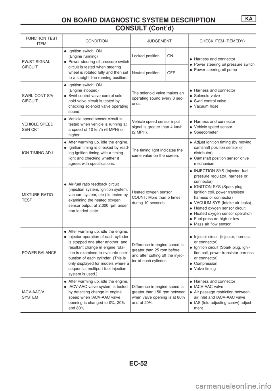
FUNCTION TEST
ITEMCONDITION JUDGEMENT CHECK ITEM (REMEDY)
PW/ST SIGNAL
CIRCUIT
lIgnition switch: ON
(Engine running)
lPower steering oil pressure switch
circuit is tested when steering
wheel is rotated fully and then set
to a straight line running position.Locked position ONlHarness and connector
lPower steering oil pressure switch
lPower steering oil pump
Neutral position OFF
SWRL CONT S/V
CIRCUIT
lIgnition switch: ON
(Engine stopped)
lSwirl control valve control sole-
noid valve circuit is tested by
checking solenoid valve operating
sound.The solenoid valve makes an
operating sound every 3 sec-
onds.
lHarness and connector
lSolenoid valve
lSwirl control valve
lVacuum hose
VEHICLE SPEED
SEN CKT
lVehicle speed sensor circuit is
tested when vehicle is running at
a speed of 10 km/h (6 MPH) or
higher.Vehicle speed sensor input
signal is greater than 4 km/h
(2 MPH).lHarness and connector
lVehicle speed sensor
lSpeedometer
IGN TIMING ADJ
lAfter warming up, idle the engine.
lIgnition timing is checked by read-
ing ignition timing with a timing
light and checking whether it
agrees with specifications.The timing light indicates the
same value on the screen.
lAdjust ignition timing (by moving
camshaft position sensor or
distributor)
lCamshaft position sensor drive
mechanism
MIXTURE RATIO
TEST
lAir-fuel ratio feedback circuit
(injection system, ignition system,
vacuum system, etc.) is tested by
examining the heated oxygen
sensor output at 2,000 rpm under
non-loaded state.Heated oxygen sensor
COUNT: More than 5 times
during 10 seconds
lINJECTION SYS (Injector, fuel
pressure regulator, harness or
connector)
lIGNITION SYS (Spark plug,
ignition coil, power transistor
harness or connector)
lVACUUM SYS (Intake air leaks)
lHeated oxygen sensor circuit
lHeated oxygen sensor operation
lFuel pressure high or low
lMass air flow sensor
POWER BALANCE
lAfter warming up, idle the engine.
lInjector operation of each cylinder
is stopped one after another, and
resultant change in engine rota-
tion is examined to evaluate com-
bustion of each cylinder. (This is
only displayed for models where a
sequential multiport fuel injection
system is used.)Difference in engine speed is
greater than 25 rpm before
and after cutting off the injec-
tor of each cylinder.lInjector circuit (Injector, harness
or connector)
lIgnition circuit (Spark plug, igni-
tion coil, power transistor harness
or connector)
lCompression
lValve timing
IACV-AAC/V
SYSTEM
lAfter warming up, idle the engine.
lIACV-AAC valve system is tested
by detecting change in engine
speed when IACV-AAC valve
opening is changed to 0%, 20%
and 80%.Difference in engine speed is
greater than 150 rpm between
when valve opening is at 80%
and at 20%.
lHarness and connector
lIACV-AAC valve
lAir passage restriction between
air inlet and IACV-AAC valve
lIAS (Idle adjusting screw) adjust-
ment
ON BOARD DIAGNOSTIC SYSTEM DESCRIPTIONKA
CONSULT (Cont'd)
EC-52
Page 210 of 1659
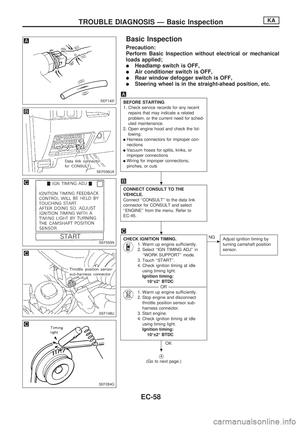
Basic Inspection
Precaution:
Perform Basic Inspection without electrical or mechanical
loads applied;
lHeadlamp switch is OFF,
lAir conditioner switch is OFF,
lRear window defogger switch is OFF,
lSteering wheel is in the straight-ahead position, etc.
BEFORE STARTING
1. Check service records for any recent
repairs that may indicate a related
problem, or the current need for sched-
uled maintenance.
2. Open engine hood and check the fol-
lowing:
lHarness connectors for improper con-
nections
lVacuum hoses for splits, kinks, or
improper connections
lWiring for improper connections,
pinches, or cuts
CONNECT CONSULT TO THE
VEHICLE.
Connect ``CONSULT'' to the data link
connector for CONSULT and select
``ENGINE'' from the menu. Refer to
EC-45.
CHECK IGNITION TIMING.
1. Warm up engine sufficiently.
2. Select ``IGN TIMING ADJ'' in
``WORK SUPPORT'' mode.
3. Touch ``START''.
4. Check ignition timing at idle
using timing light.
Ignition timing:
10É 2É BTDC
----------------------------------------------------------------------------------------------------------------------------------OR----------------------------------------------------------------------------------------------------------------------------------
1. Warm up engine sufficiently.
2. Stop engine and disconnect
throttle position sensor sub-
harness connector.
3. Start engine.
4. Check ignition timing at idle
using timing light.
Ignition timing:
10É 2É BTDC
OK
cNG
Adjust ignition timing by
turning camshaft position
sensor.
VA
(Go to next page.)
SEF142I
SEF056UA
SEF555N
SEF148U
SEF284G
.
.
.
TROUBLE DIAGNOSIS Ð Basic InspectionKA
EC-58
Page 216 of 1659
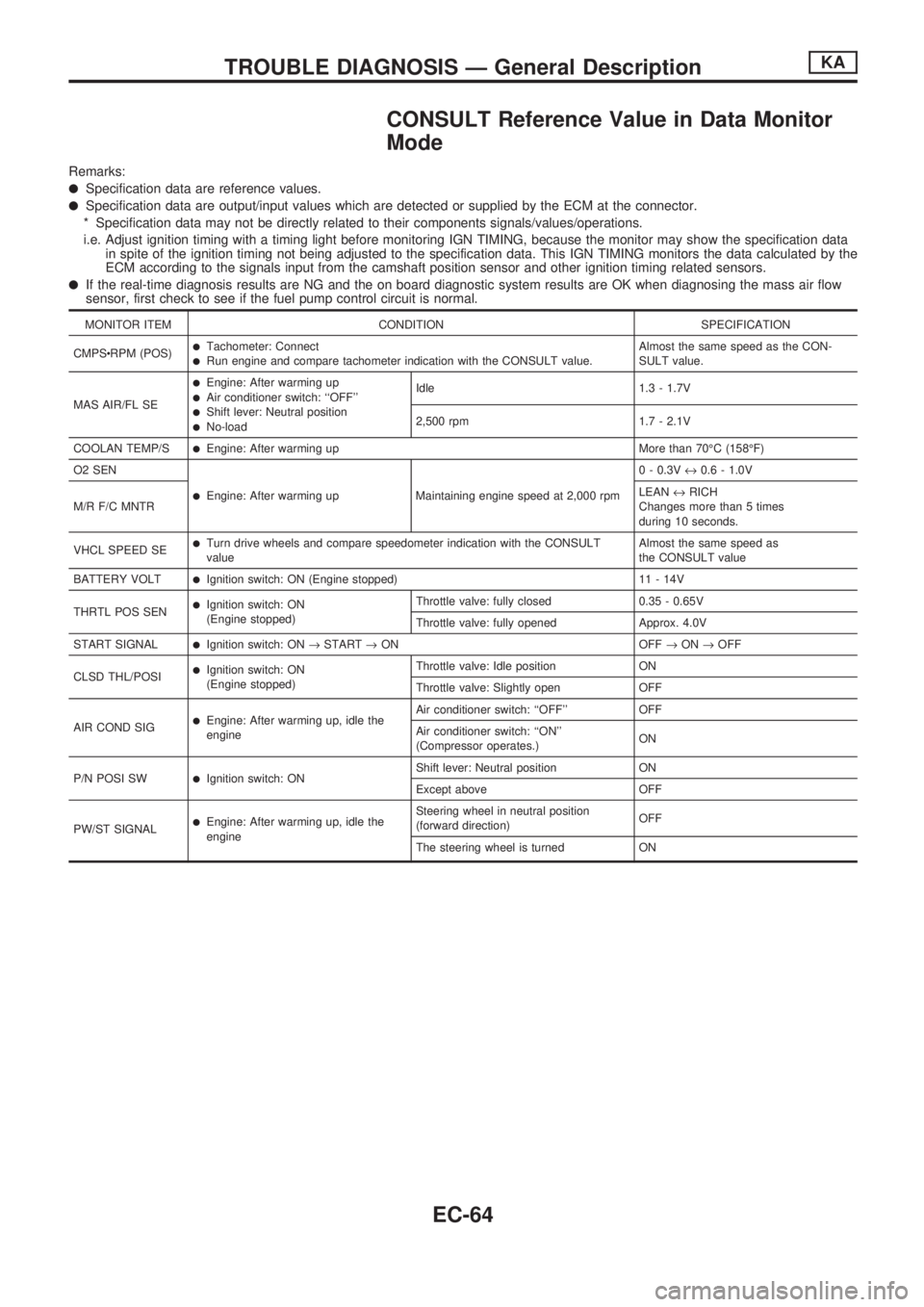
CONSULT Reference Value in Data Monitor
Mode
Remarks:
lSpecification data are reference values.
lSpecification data are output/input values which are detected or supplied by the ECM at the connector.
* Specification data may not be directly related to their components signals/values/operations.
i.e. Adjust ignition timing with a timing light before monitoring IGN TIMING, because the monitor may show the specification data
in spite of the ignition timing not being adjusted to the specification data. This IGN TIMING monitors the data calculated by the
ECM according to the signals input from the camshaft position sensor and other ignition timing related sensors.
lIf the real-time diagnosis results are NG and the on board diagnostic system results are OK when diagnosing the mass air flow
sensor, first check to see if the fuel pump control circuit is normal.
MONITOR ITEM CONDITION SPECIFICATION
CMPScRPM (POS)
lTachometer: ConnectlRun engine and compare tachometer indication with the CONSULT value.Almost the same speed as the CON-
SULT value.
MAS AIR/FL SE
lEngine: After warming uplAir conditioner switch: ``OFF''lShift lever: Neutral positionlNo-loadIdle 1.3 - 1.7V
2,500 rpm 1.7 - 2.1V
COOLAN TEMP/S
lEngine: After warming up More than 70ÉC (158ÉF)
O2 SEN
lEngine: After warming up Maintaining engine speed at 2,000 rpm0 - 0.3V«0.6 - 1.0V
M/R F/C MNTRLEAN«RICH
Changes more than 5 times
during 10 seconds.
VHCL SPEED SE
lTurn drive wheels and compare speedometer indication with the CONSULT
valueAlmost the same speed as
the CONSULT value
BATTERY VOLT
lIgnition switch: ON (Engine stopped) 11 - 14V
THRTL POS SEN
lIgnition switch: ON
(Engine stopped)Throttle valve: fully closed 0.35 - 0.65V
Throttle valve: fully opened Approx. 4.0V
START SIGNAL
lIgnition switch: ON®START®ON OFF®ON®OFF
CLSD THL/POSI
lIgnition switch: ON
(Engine stopped)Throttle valve: Idle position ON
Throttle valve: Slightly open OFF
AIR COND SIG
lEngine: After warming up, idle the
engineAir conditioner switch: ``OFF'' OFF
Air conditioner switch: ``ON''
(Compressor operates.)ON
P/N POSI SW
lIgnition switch: ONShift lever: Neutral position ON
Except above OFF
PW/ST SIGNAL
lEngine: After warming up, idle the
engineSteering wheel in neutral position
(forward direction)OFF
The steering wheel is turned ON
TROUBLE DIAGNOSIS Ð General DescriptionKA
EC-64
Page 388 of 1659

ELECTRICAL SYSTEM
SECTION
EL
When you read wiring diagrams:
lRead GI section, ``HOW TO READ WIRING DIAGRAMS''.
When you perform trouble diagnoses, read GI section, ``HOW TO FOLLOW FLOW CHART IN
TROUBLE DIAGNOSES'' and ``HOW TO PERFORM EFFICIENT DIAGNOSIS FOR AN ELECTRI-
CAL INCIDENT''.
CONTENTS
PRECAUTIONS......................................................... 1
Supplemental Restraint System (SRS) ``AIR
BAG'' (4WD models).............................................. 1
Supplemental Restraint System (SRS) ``AIR
BAG'' (2WD models).............................................. 1
HARNESS CONNECTOR.......................................... 2
Description ............................................................. 2
STANDARDIZED RELAY.......................................... 3
Description ............................................................. 3
POWER SUPPLY ROUTING..................................... 5
Schematic .............................................................. 5
Wiring Diagram - POWER -................................... 6
Fuse ..................................................................... 13
Fusible Link .......................................................... 13
Circuit Breaker Inspection.................................... 13
GROUND DISTRIBUTION....................................... 14
BATTERY................................................................. 18
How to Handle Battery......................................... 18
Battery Test and Charging Chart......................... 21
Service Data and Specifications (SDS) ............... 25
STARTING SYSTEM............................................... 26
Wiring Diagram - START - .................................. 26
Trouble Diagnoses ............................................... 27
Construction ......................................................... 28
Removal and Installation ..................................... 30
Inspection ............................................................. 30
Assembly.............................................................. 32
Service Data and Specifications (SDS) ............... 33
CHARGING SYSTEM.............................................. 34
Wiring Diagram - CHARGE -/Gasoline Engine ... 34
Wiring Diagram - CHARGE -/Diesel Engine ....... 35Trouble Diagnoses ............................................... 36
Construction ......................................................... 38
Removal and Installation ..................................... 39
Disassembly ......................................................... 39
Inspection ............................................................. 39
Assembly.............................................................. 40
Service Data and Specifications (SDS) ............... 41
COMBINATION SWITCH........................................ 42
Check ................................................................... 42
Replacement ........................................................ 43
HEADLAMP - Conventional Type -....................... 44
Wiring Diagram - H/LAMP -/LHD Models ............ 44
Wiring Diagram - H/LAMP -/RHD Models ........... 46
Trouble Diagnoses ............................................... 48
Bulb Replacement................................................ 49
Aiming Adjustment ............................................... 49
Low Beam ............................................................ 50
HEADLAMP - Daytime Light System -................. 51
System Description .............................................. 51
Schematic ............................................................ 53
Wiring Diagram - DTRL - ..................................... 54
Trouble Diagnoses ............................................... 57
Bulb Replacement................................................ 57
Aiming Adjustment ............................................... 57
HEADLAMP - Dim-dip Lamp System -................. 58
System Description .............................................. 58
Schematic ............................................................ 58
Wiring Diagram - DIMDIP -.................................. 59
Trouble Diagnoses ............................................... 62
Bulb Replacement................................................ 62
Aiming Adjustment ............................................... 62
EL
Page 404 of 1659
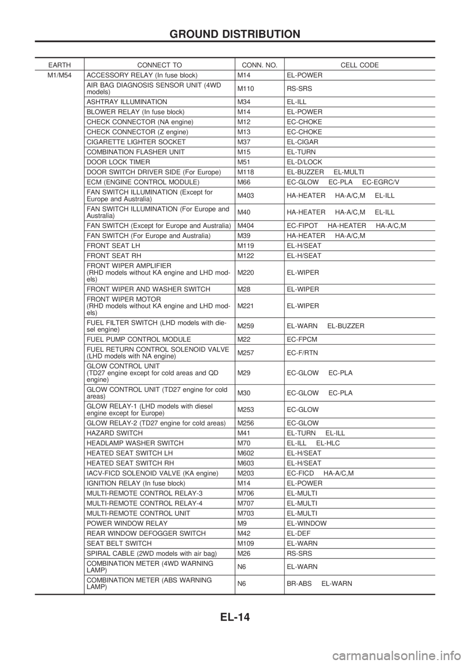
EARTH CONNECT TO CONN. NO. CELL CODE
M1/M54 ACCESSORY RELAY (In fuse block) M14 EL-POWER
AIR BAG DIAGNOSIS SENSOR UNIT (4WD
models)M110 RS-SRS
ASHTRAY ILLUMINATION M34 EL-ILL
BLOWER RELAY (In fuse block) M14 EL-POWER
CHECK CONNECTOR (NA engine) M12 EC-CHOKE
CHECK CONNECTOR (Z engine) M13 EC-CHOKE
CIGARETTE LIGHTER SOCKET M37 EL-CIGAR
COMBINATION FLASHER UNIT M15 EL-TURN
DOOR LOCK TIMER M51 EL-D/LOCK
DOOR SWITCH DRIVER SIDE (For Europe) M118 EL-BUZZER EL-MULTI
ECM (ENGINE CONTROL MODULE) M66 EC-GLOW EC-PLA EC-EGRC/V
FAN SWITCH ILLUMINATION (Except for
Europe and Australia)M403 HA-HEATER HA-A/C,M EL-ILL
FAN SWITCH ILLUMINATION (For Europe and
Australia)M40 HA-HEATER HA-A/C,M EL-ILL
FAN SWITCH (Except for Europe and Australia) M404 EC-FIPOT HA-HEATER HA-A/C,M
FAN SWITCH (For Europe and Australia) M39 HA-HEATER HA-A/C,M
FRONT SEAT LH M119 EL-H/SEAT
FRONT SEAT RH M122 EL-H/SEAT
FRONT WIPER AMPLIFIER
(RHD models without KA engine and LHD mod-
els)M220 EL-WIPER
FRONT WIPER AND WASHER SWITCH M28 EL-WIPER
FRONT WIPER MOTOR
(RHD models without KA engine and LHD mod-
els)M221 EL-WIPER
FUEL FILTER SWITCH (LHD models with die-
sel engine)M259 EL-WARN EL-BUZZER
FUEL PUMP CONTROL MODULE M22 EC-FPCM
FUEL RETURN CONTROL SOLENOID VALVE
(LHD models with NA engine)M257 EC-F/RTN
GLOW CONTROL UNIT
(TD27 engine except for cold areas and QD
engine)M29 EC-GLOW EC-PLA
GLOW CONTROL UNIT (TD27 engine for cold
areas)M30 EC-GLOW EC-PLA
GLOW RELAY-1 (LHD models with diesel
engine except for Europe)M253 EC-GLOW
GLOW RELAY-2 (TD27 engine for cold areas) M256 EC-GLOW
HAZARD SWITCH M41 EL-TURN EL-ILL
HEADLAMP WASHER SWITCH M70 EL-ILL EL-HLC
HEATED SEAT SWITCH LH M602 EL-H/SEAT
HEATED SEAT SWITCH RH M603 EL-H/SEAT
IACV-FICD SOLENOID VALVE (KA engine) M203 EC-FICD HA-A/C,M
IGNITION RELAY (In fuse block) M14 EL-POWER
MULTI-REMOTE CONTROL RELAY-3 M706 EL-MULTI
MULTI-REMOTE CONTROL RELAY-4 M707 EL-MULTI
MULTI-REMOTE CONTROL UNIT M703 EL-MULTI
POWER WINDOW RELAY M9 EL-WINDOW
REAR WINDOW DEFOGGER SWITCH M42 EL-DEF
SEAT BELT SWITCH M109 EL-WARN
SPIRAL CABLE (2WD models with air bag) M26 RS-SRS
COMBINATION METER (4WD WARNING
LAMP)N6 EL-WARN
COMBINATION METER (ABS WARNING
LAMP)N6 BR-ABS EL-WARN
GROUND DISTRIBUTION
EL-14
Page 506 of 1659
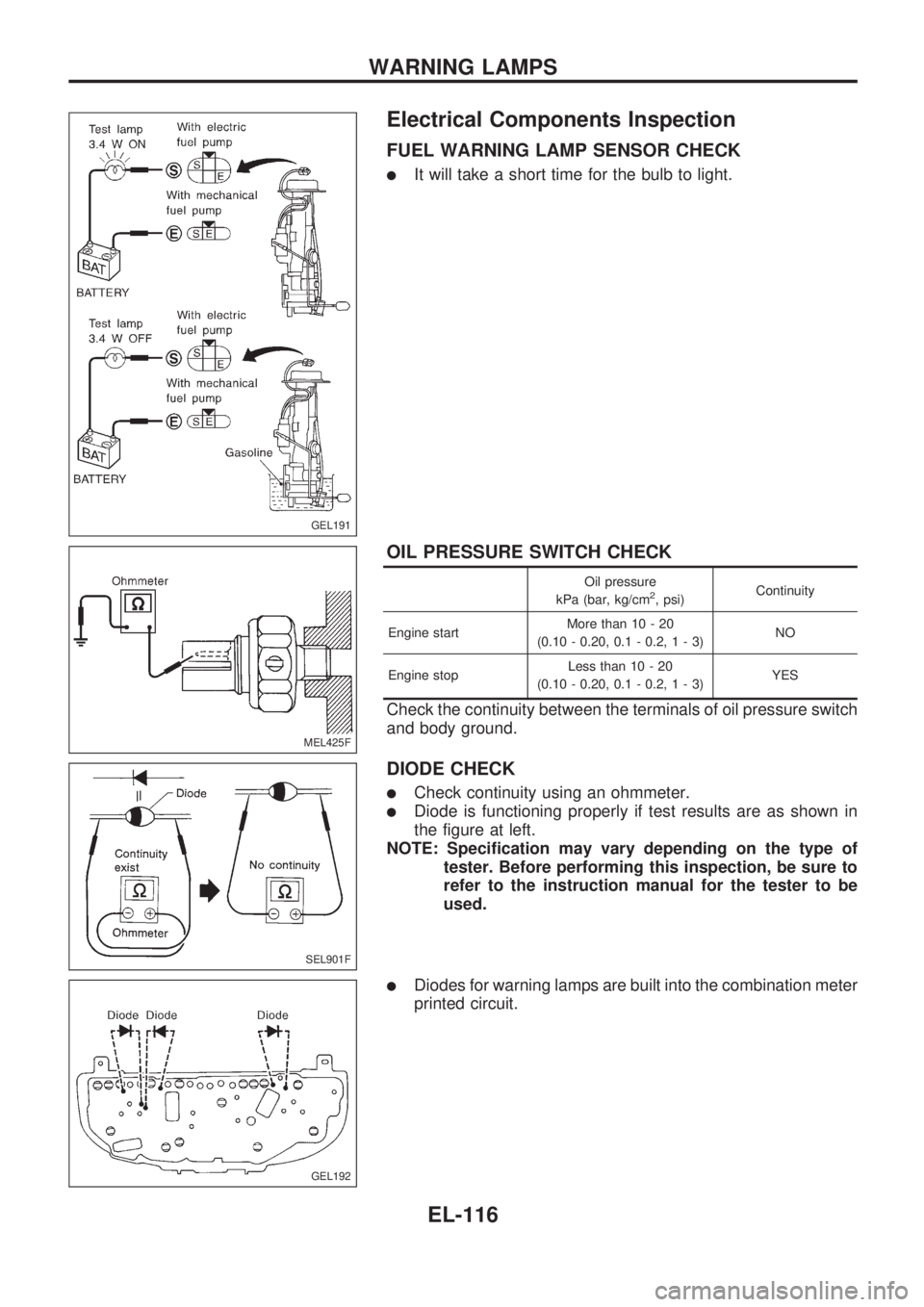
Electrical Components Inspection
FUEL WARNING LAMP SENSOR CHECK
lIt will take a short time for the bulb to light.
OIL PRESSURE SWITCH CHECK
Oil pressure
kPa (bar, kg/cm2, psi)Continuity
Engine startMore than 10 - 20
(0.10 - 0.20, 0.1 - 0.2,1-3)NO
Engine stopLess than 10 - 20
(0.10 - 0.20, 0.1 - 0.2,1-3)YES
Check the continuity between the terminals of oil pressure switch
and body ground.
DIODE CHECK
lCheck continuity using an ohmmeter.
lDiode is functioning properly if test results are as shown in
the figure at left.
NOTE: Specification may vary depending on the type of
tester. Before performing this inspection, be sure to
refer to the instruction manual for the tester to be
used.
lDiodes for warning lamps are built into the combination meter
printed circuit.
GEL191
MEL425F
SEL901F
GEL192
WARNING LAMPS
EL-116
Page 578 of 1659
Trouble Diagnoses
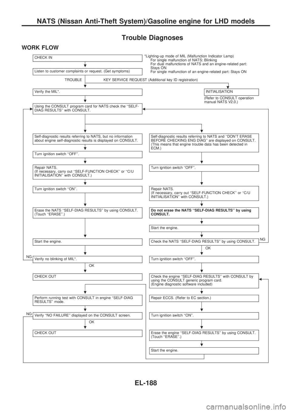
WORK FLOW
CHECK IN*Lighting-up mode of MIL (Malfunction Indicator Lamp)
For single malfunction of NATS: Blinking
For dual malfunctions of NATS and an engine-related part:
Stays ON
For single malfunction of an engine-related part: Stays ON Listen to customer complaints or request. (Get symptoms)
TROUBLE KEY SERVICE REQUEST (Additional key ID registration)
.Verify the MIL*.INITIALISATION
(Refer to CONSULT operation
manual NATS V2.0.)
cUsing the CONSULT program card for NATS check the ``SELF-
DIAG RESULTS'' with CONSULT.b
Self-diagnostic results referring to NATS, but no information
about engine self-diagnostic results is displayed on CONSULT.Self-diagnostic results referring to NATS and ``DON'T ERASE
BEFORE CHECKING ENG DIAG'' are displayed on CONSULT.
(This means that engine trouble data has been detected in
ECM.)
Turn ignition switch ``OFF''.
Repair NATS.
(If necessary, carry out ``SELF-FUNCTION CHECK'' or ``C/U
INITIALISATION'' with CONSULT.)Turn ignition switch ``OFF''.
Turn ignition switch ``ON''.Repair NATS.
(If necessary, carry out ``SELF-FUNCTION CHECK'' or ``C/U
INITIALISATION'' with CONSULT.)
Erase the NATS ``SELF-DIAG RESULTS'' by using CONSULT.
(Touch ``ERASE''.)Do not erase the NATS ``SELF-DIAG RESULTS'' by using
CONSULT.
Start the engine.
Start the engine.Check the NATS ``SELF-DIAG RESULTS'' by using CONSULT.
OKNG
NGVerify no blinking of MIL*.
OKTurn ignition switch ``OFF''.
CHECK OUTCheck the engine ``SELF-DIAG RESULTS'' with CONSULT by
using the CONSULT generic program card.
(Engine diagnostic software included)b
Perform running test with CONSULT in engine ``SELF-DIAG
RESULTS'' mode.Repair ECCS. (Refer to EC section.)
NGVerify ``NO FAILURE'' displayed on the CONSULT screen.
OKTurn ignition switch ``ON''.
CHECK OUTErase the engine ``SELF-DIAG RESULTS'' by using CONSULT.
(Touch ``ERASE''.)
Start the engine.
.
.
.
..
.
..
..
..
.
..
..
..
..
..
..
.
NATS (Nissan Anti-Theft System)/Gasoline engine for LHD models
EL-188
Page 579 of 1659
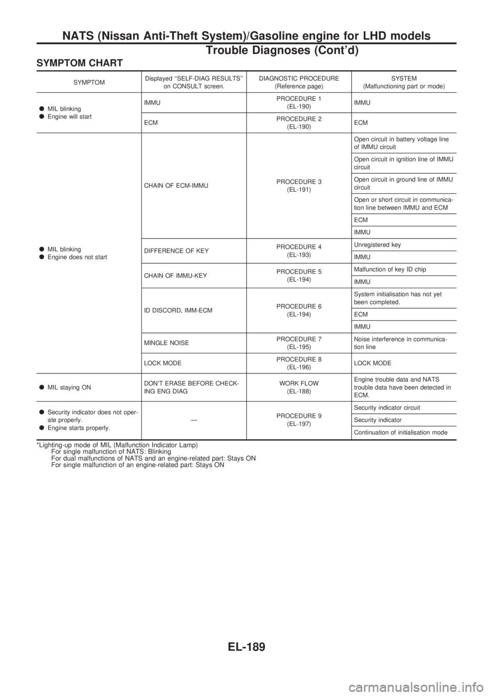
SYMPTOM CHART
SYMPTOMDisplayed ``SELF-DIAG RESULTS''
on CONSULT screen.DIAGNOSTIC PROCEDURE
(Reference page)SYSTEM
(Malfunctioning part or mode)
lMIL blinkinglEngine will startIMMUPROCEDURE 1
(EL-190)IMMU
ECMPROCEDURE 2
(EL-190)ECM
lMIL blinkinglEngine does not startCHAIN OF ECM-IMMUPROCEDURE 3
(EL-191)Open circuit in battery voltage line
of IMMU circuit
Open circuit in ignition line of IMMU
circuit
Open circuit in ground line of IMMU
circuit
Open or short circuit in communica-
tion line between IMMU and ECM
ECM
IMMU
DIFFERENCE OF KEYPROCEDURE 4
(EL-193)Unregistered key
IMMU
CHAIN OF IMMU-KEYPROCEDURE 5
(EL-194)Malfunction of key ID chip
IMMU
ID DISCORD, IMM-ECMPROCEDURE 6
(EL-194)System initialisation has not yet
been completed.
ECM
IMMU
MINGLE NOISEPROCEDURE 7
(EL-195)Noise interference in communica-
tion line
LOCK MODEPROCEDURE 8
(EL-196)LOCK MODE
lMIL staying ONDON'T ERASE BEFORE CHECK-
ING ENG DIAGWORK FLOW
(EL-188)Engine trouble data and NATS
trouble data have been detected in
ECM.
lSecurity indicator does not oper-
ate properly.
lEngine starts properly.ÐPROCEDURE 9
(EL-197)Security indicator circuit
Security indicator
Continuation of initialisation mode
*Lighting-up mode of MIL (Malfunction Indicator Lamp)
For single malfunction of NATS: Blinking
For dual malfunctions of NATS and an engine-related part: Stays ON
For single malfunction of an engine-related part: Stays ON
NATS (Nissan Anti-Theft System)/Gasoline engine for LHD models
Trouble Diagnoses (Cont'd)
EL-189