1998 NISSAN PICK-UP check engine light
[x] Cancel search: check engine lightPage 993 of 1659

Changing Oil Filter
1. Remove oil filter with a suitable tool.
WARNING:
Be careful not to burn yourself, as the engine and the engine
oil are hot.
2. Before installing a new oil filter, clean the oil filter mounting
surface on cylinder block, and coat the rubber seal of oil fil-
ter with a little engine oil.
3. Screw in the oil filter until a slight resistance is felt, then
tighten additionally more than 2/3 turn.
4. Add engine oil.
Refer to ``Changing Engine Oil'', MA-19.
Checking and Changing Spark Plugs
1. Disconnect ignition wires from spark plugs at boot.
Do not pull on the wire.
2. Remove spark plugs with spark plug wrench.
3. Clean plugs in sand blast cleaner.
4. Check insulator for cracks or chips, gasket for damage or
deterioration and electrode for wear and burning. If they are
excessively worn away, replace with new spark plugs.
Spark plug:
Make NGK
Standard type ZFR5E-11
Hot type ZFR4E-11
Cold type ZFR6E-11
SMA946C
SMA010
SMA229B
SMA017-A
SMA581C
ENGINE MAINTENANCEKA
MA-20
Page 1001 of 1659
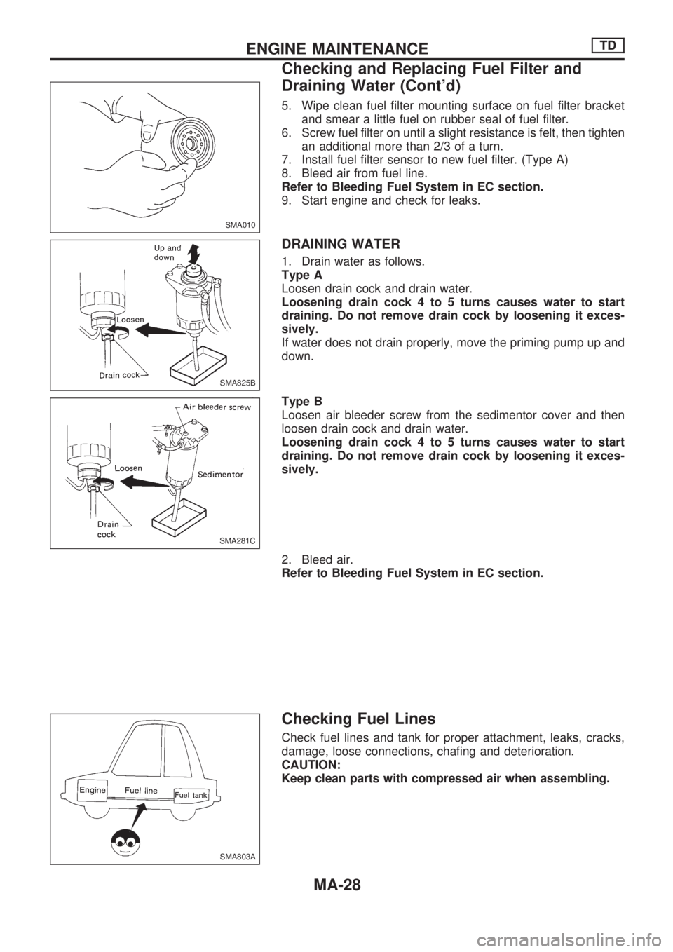
5. Wipe clean fuel filter mounting surface on fuel filter bracket
and smear a little fuel on rubber seal of fuel filter.
6. Screw fuel filter on until a slight resistance is felt, then tighten
an additional more than 2/3 of a turn.
7. Install fuel filter sensor to new fuel filter. (Type A)
8. Bleed air from fuel line.
Refer to Bleeding Fuel System in EC section.
9. Start engine and check for leaks.
DRAINING WATER
1. Drain water as follows.
Type A
Loosen drain cock and drain water.
Loosening drain cock 4 to 5 turns causes water to start
draining. Do not remove drain cock by loosening it exces-
sively.
If water does not drain properly, move the priming pump up and
down.
Type B
Loosen air bleeder screw from the sedimentor cover and then
loosen drain cock and drain water.
Loosening drain cock 4 to 5 turns causes water to start
draining. Do not remove drain cock by loosening it exces-
sively.
2. Bleed air.
Refer to Bleeding Fuel System in EC section.
Checking Fuel Lines
Check fuel lines and tank for proper attachment, leaks, cracks,
damage, loose connections, chafing and deterioration.
CAUTION:
Keep clean parts with compressed air when assembling.
SMA010
SMA825B
SMA281C
SMA803A
ENGINE MAINTENANCETD
Checking and Replacing Fuel Filter and
Draining Water (Cont'd)
MA-28
Page 1003 of 1659
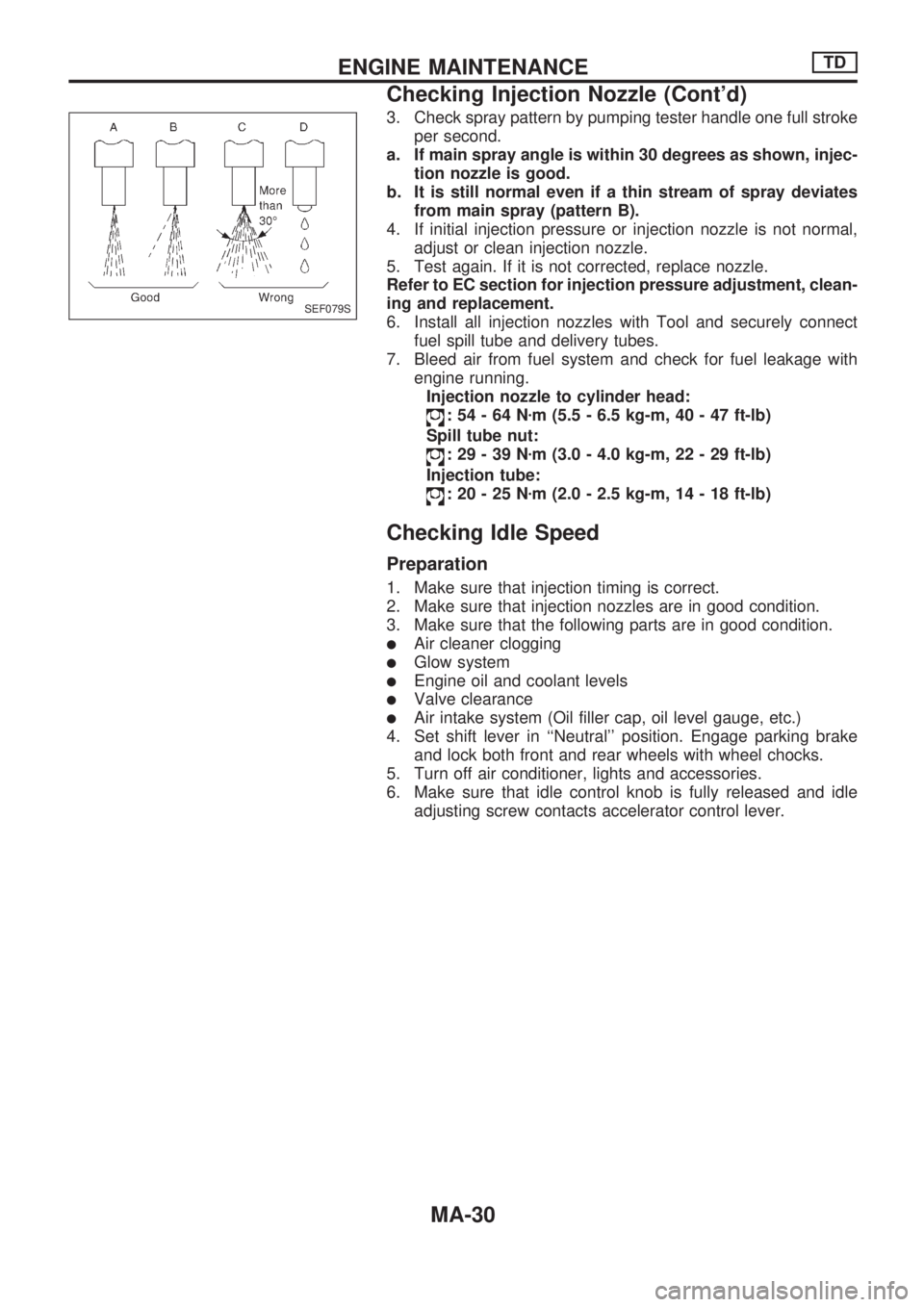
3. Check spray pattern by pumping tester handle one full stroke
per second.
a. If main spray angle is within 30 degrees as shown, injec-
tion nozzle is good.
b. It is still normal even if a thin stream of spray deviates
from main spray (pattern B).
4. If initial injection pressure or injection nozzle is not normal,
adjust or clean injection nozzle.
5. Test again. If it is not corrected, replace nozzle.
Refer to EC section for injection pressure adjustment, clean-
ing and replacement.
6. Install all injection nozzles with Tool and securely connect
fuel spill tube and delivery tubes.
7. Bleed air from fuel system and check for fuel leakage with
engine running.
Injection nozzle to cylinder head:
:54-64Nzm (5.5 - 6.5 kg-m, 40 - 47 ft-lb)
Spill tube nut:
:29-39Nzm (3.0 - 4.0 kg-m, 22 - 29 ft-lb)
Injection tube:
:20-25Nzm (2.0 - 2.5 kg-m, 14 - 18 ft-lb)
Checking Idle Speed
Preparation
1. Make sure that injection timing is correct.
2. Make sure that injection nozzles are in good condition.
3. Make sure that the following parts are in good condition.
lAir cleaner clogging
lGlow system
lEngine oil and coolant levels
lValve clearance
lAir intake system (Oil filler cap, oil level gauge, etc.)
4. Set shift lever in ``Neutral'' position. Engage parking brake
and lock both front and rear wheels with wheel chocks.
5. Turn off air conditioner, lights and accessories.
6. Make sure that idle control knob is fully released and idle
adjusting screw contacts accelerator control lever.
SEF079S
ENGINE MAINTENANCETD
Checking Injection Nozzle (Cont'd)
MA-30
Page 1227 of 1659
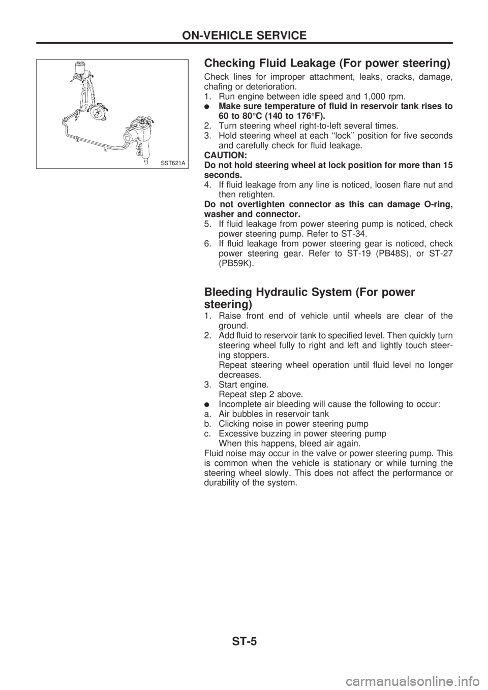
Checking Fluid Leakage (For power steering)
Check lines for improper attachment, leaks, cracks, damage,
chafing or deterioration.
1. Run engine between idle speed and 1,000 rpm.
lMake sure temperature of fluid in reservoir tank rises to
60 to 80ÉC (140 to 176ÉF).
2. Turn steering wheel right-to-left several times.
3. Hold steering wheel at each ``lock'' position for five seconds
and carefully check for fluid leakage.
CAUTION:
Do not hold steering wheel at lock position for more than 15
seconds.
4. If fluid leakage from any line is noticed, loosen flare nut and
then retighten.
Do not overtighten connector as this can damage O-ring,
washer and connector.
5. If fluid leakage from power steering pump is noticed, check
power steering pump. Refer to ST-34.
6. If fluid leakage from power steering gear is noticed, check
power steering gear. Refer to ST-19 (PB48S), or ST-27
(PB59K).
Bleeding Hydraulic System (For power
steering)
1. Raise front end of vehicle until wheels are clear of the
ground.
2. Add fluid to reservoir tank to specified level. Then quickly turn
steering wheel fully to right and left and lightly touch steer-
ing stoppers.
Repeat steering wheel operation until fluid level no longer
decreases.
3. Start engine.
Repeat step 2 above.
lIncomplete air bleeding will cause the following to occur:
a. Air bubbles in reservoir tank
b. Clicking noise in power steering pump
c. Excessive buzzing in power steering pump
When this happens, bleed air again.
Fluid noise may occur in the valve or power steering pump. This
is common when the vehicle is stationary or while turning the
steering wheel slowly. This does not affect the performance or
durability of the system.
SST621A
ON-VEHICLE SERVICE
ST-5
Page 1234 of 1659
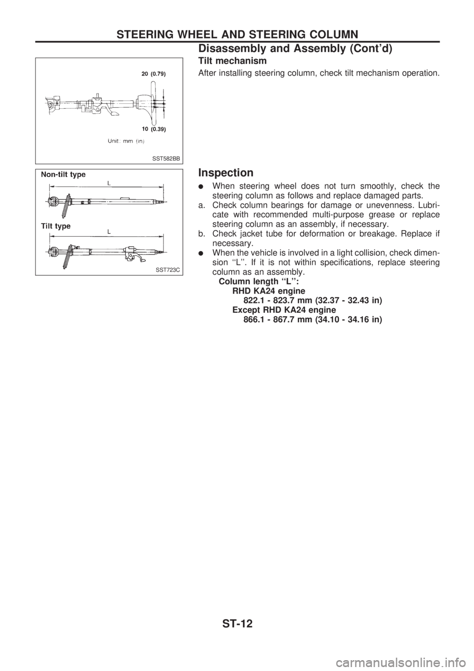
Tilt mechanism
After installing steering column, check tilt mechanism operation.
Inspection
lWhen steering wheel does not turn smoothly, check the
steering column as follows and replace damaged parts.
a. Check column bearings for damage or unevenness. Lubri-
cate with recommended multi-purpose grease or replace
steering column as an assembly, if necessary.
b. Check jacket tube for deformation or breakage. Replace if
necessary.
lWhen the vehicle is involved in a light collision, check dimen-
sion ``L''. If it is not within specifications, replace steering
column as an assembly.
Column length ``L'':
RHD KA24 engine
822.1 - 823.7 mm (32.37 - 32.43 in)
Except RHD KA24 engine
866.1 - 867.7 mm (34.10 - 34.16 in)
SST582BB
SST723C
STEERING WHEEL AND STEERING COLUMN
Disassembly and Assembly (Cont'd)
ST-12
Page 1296 of 1659
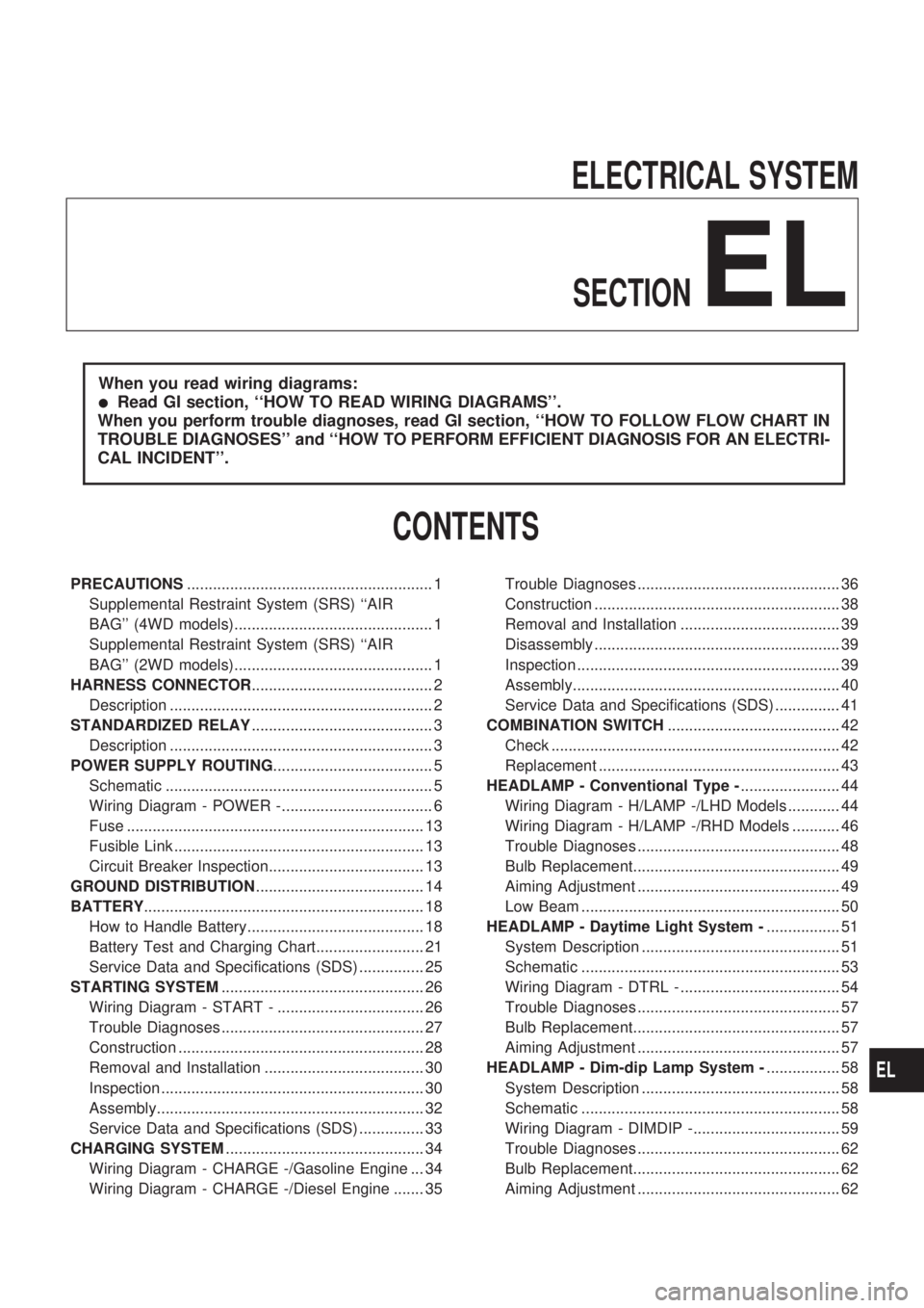
ELECTRICAL SYSTEM
SECTION
EL
When you read wiring diagrams:
lRead GI section, ``HOW TO READ WIRING DIAGRAMS''.
When you perform trouble diagnoses, read GI section, ``HOW TO FOLLOW FLOW CHART IN
TROUBLE DIAGNOSES'' and ``HOW TO PERFORM EFFICIENT DIAGNOSIS FOR AN ELECTRI-
CAL INCIDENT''.
CONTENTS
PRECAUTIONS......................................................... 1
Supplemental Restraint System (SRS) ``AIR
BAG'' (4WD models).............................................. 1
Supplemental Restraint System (SRS) ``AIR
BAG'' (2WD models).............................................. 1
HARNESS CONNECTOR.......................................... 2
Description ............................................................. 2
STANDARDIZED RELAY.......................................... 3
Description ............................................................. 3
POWER SUPPLY ROUTING..................................... 5
Schematic .............................................................. 5
Wiring Diagram - POWER -................................... 6
Fuse ..................................................................... 13
Fusible Link .......................................................... 13
Circuit Breaker Inspection.................................... 13
GROUND DISTRIBUTION....................................... 14
BATTERY................................................................. 18
How to Handle Battery......................................... 18
Battery Test and Charging Chart......................... 21
Service Data and Specifications (SDS) ............... 25
STARTING SYSTEM............................................... 26
Wiring Diagram - START - .................................. 26
Trouble Diagnoses ............................................... 27
Construction ......................................................... 28
Removal and Installation ..................................... 30
Inspection ............................................................. 30
Assembly.............................................................. 32
Service Data and Specifications (SDS) ............... 33
CHARGING SYSTEM.............................................. 34
Wiring Diagram - CHARGE -/Gasoline Engine ... 34
Wiring Diagram - CHARGE -/Diesel Engine ....... 35Trouble Diagnoses ............................................... 36
Construction ......................................................... 38
Removal and Installation ..................................... 39
Disassembly ......................................................... 39
Inspection ............................................................. 39
Assembly.............................................................. 40
Service Data and Specifications (SDS) ............... 41
COMBINATION SWITCH........................................ 42
Check ................................................................... 42
Replacement ........................................................ 43
HEADLAMP - Conventional Type -....................... 44
Wiring Diagram - H/LAMP -/LHD Models ............ 44
Wiring Diagram - H/LAMP -/RHD Models ........... 46
Trouble Diagnoses ............................................... 48
Bulb Replacement................................................ 49
Aiming Adjustment ............................................... 49
Low Beam ............................................................ 50
HEADLAMP - Daytime Light System -................. 51
System Description .............................................. 51
Schematic ............................................................ 53
Wiring Diagram - DTRL - ..................................... 54
Trouble Diagnoses ............................................... 57
Bulb Replacement................................................ 57
Aiming Adjustment ............................................... 57
HEADLAMP - Dim-dip Lamp System -................. 58
System Description .............................................. 58
Schematic ............................................................ 58
Wiring Diagram - DIMDIP -.................................. 59
Trouble Diagnoses ............................................... 62
Bulb Replacement................................................ 62
Aiming Adjustment ............................................... 62
EL
Page 1312 of 1659
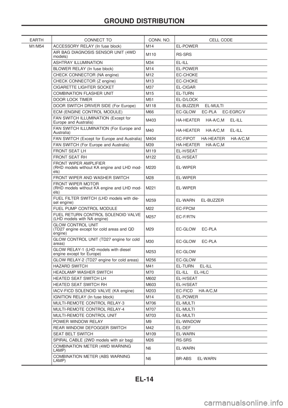
EARTH CONNECT TO CONN. NO. CELL CODE
M1/M54 ACCESSORY RELAY (In fuse block) M14 EL-POWER
AIR BAG DIAGNOSIS SENSOR UNIT (4WD
models)M110 RS-SRS
ASHTRAY ILLUMINATION M34 EL-ILL
BLOWER RELAY (In fuse block) M14 EL-POWER
CHECK CONNECTOR (NA engine) M12 EC-CHOKE
CHECK CONNECTOR (Z engine) M13 EC-CHOKE
CIGARETTE LIGHTER SOCKET M37 EL-CIGAR
COMBINATION FLASHER UNIT M15 EL-TURN
DOOR LOCK TIMER M51 EL-D/LOCK
DOOR SWITCH DRIVER SIDE (For Europe) M118 EL-BUZZER EL-MULTI
ECM (ENGINE CONTROL MODULE) M66 EC-GLOW EC-PLA EC-EGRC/V
FAN SWITCH ILLUMINATION (Except for
Europe and Australia)M403 HA-HEATER HA-A/C,M EL-ILL
FAN SWITCH ILLUMINATION (For Europe and
Australia)M40 HA-HEATER HA-A/C,M EL-ILL
FAN SWITCH (Except for Europe and Australia) M404 EC-FIPOT HA-HEATER HA-A/C,M
FAN SWITCH (For Europe and Australia) M39 HA-HEATER HA-A/C,M
FRONT SEAT LH M119 EL-H/SEAT
FRONT SEAT RH M122 EL-H/SEAT
FRONT WIPER AMPLIFIER
(RHD models without KA engine and LHD mod-
els)M220 EL-WIPER
FRONT WIPER AND WASHER SWITCH M28 EL-WIPER
FRONT WIPER MOTOR
(RHD models without KA engine and LHD mod-
els)M221 EL-WIPER
FUEL FILTER SWITCH (LHD models with die-
sel engine)M259 EL-WARN EL-BUZZER
FUEL PUMP CONTROL MODULE M22 EC-FPCM
FUEL RETURN CONTROL SOLENOID VALVE
(LHD models with NA engine)M257 EC-F/RTN
GLOW CONTROL UNIT
(TD27 engine except for cold areas and QD
engine)M29 EC-GLOW EC-PLA
GLOW CONTROL UNIT (TD27 engine for cold
areas)M30 EC-GLOW EC-PLA
GLOW RELAY-1 (LHD models with diesel
engine except for Europe)M253 EC-GLOW
GLOW RELAY-2 (TD27 engine for cold areas) M256 EC-GLOW
HAZARD SWITCH M41 EL-TURN EL-ILL
HEADLAMP WASHER SWITCH M70 EL-ILL EL-HLC
HEATED SEAT SWITCH LH M602 EL-H/SEAT
HEATED SEAT SWITCH RH M603 EL-H/SEAT
IACV-FICD SOLENOID VALVE (KA engine) M203 EC-FICD HA-A/C,M
IGNITION RELAY (In fuse block) M14 EL-POWER
MULTI-REMOTE CONTROL RELAY-3 M706 EL-MULTI
MULTI-REMOTE CONTROL RELAY-4 M707 EL-MULTI
MULTI-REMOTE CONTROL UNIT M703 EL-MULTI
POWER WINDOW RELAY M9 EL-WINDOW
REAR WINDOW DEFOGGER SWITCH M42 EL-DEF
SEAT BELT SWITCH M109 EL-WARN
SPIRAL CABLE (2WD models with air bag) M26 RS-SRS
COMBINATION METER (4WD WARNING
LAMP)N6 EL-WARN
COMBINATION METER (ABS WARNING
LAMP)N6 BR-ABS EL-WARN
GROUND DISTRIBUTION
EL-14
Page 1414 of 1659
Electrical Components Inspection
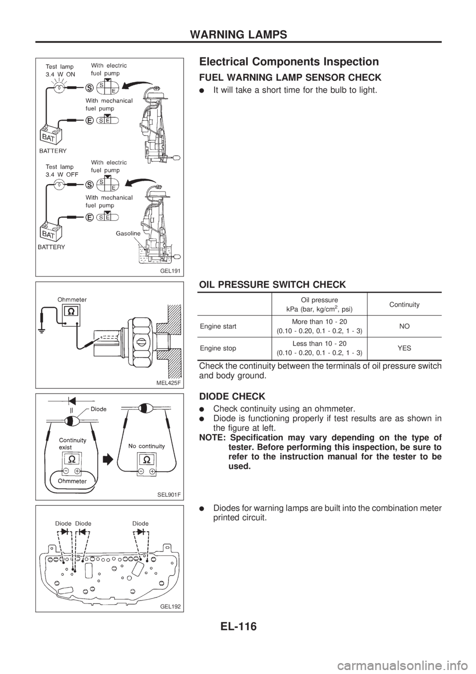
FUEL WARNING LAMP SENSOR CHECK
lIt will take a short time for the bulb to light.
OIL PRESSURE SWITCH CHECK
Oil pressure
kPa (bar, kg/cm2, psi)Continuity
Engine startMore than 10 - 20
(0.10 - 0.20, 0.1 - 0.2,1-3)NO
Engine stopLess than 10 - 20
(0.10 - 0.20, 0.1 - 0.2,1-3)YES
Check the continuity between the terminals of oil pressure switch
and body ground.
DIODE CHECK
lCheck continuity using an ohmmeter.
lDiode is functioning properly if test results are as shown in
the figure at left.
NOTE: Specification may vary depending on the type of
tester. Before performing this inspection, be sure to
refer to the instruction manual for the tester to be
used.
lDiodes for warning lamps are built into the combination meter
printed circuit.
GEL191
MEL425F
SEL901F
GEL192
WARNING LAMPS
EL-116