1998 NISSAN PICK-UP fuel cap
[x] Cancel search: fuel capPage 156 of 1659
Commercial Service Tool
FOR KA ENGINE MODELS
Tool name Description
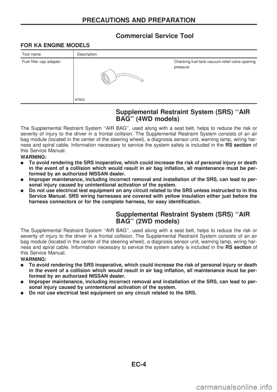
Fuel filler cap adapter
NT653
Checking fuel tank vacuum relief valve opening
pressure
Supplemental Restraint System (SRS) ``AIR
BAG'' (4WD models)
The Supplemental Restraint System ``AIR BAG'', used along with a seat belt, helps to reduce the risk or
severity of injury to the driver in a frontal collision. The Supplemental Restraint System consists of an air
bag module (located in the center of the steering wheel), a diagnosis sensor unit, warning lamp, wiring har-
ness and spiral cable. Information necessary to service the system safely is included in theRS sectionof
this Service Manual.
WARNING:
lTo avoid rendering the SRS inoperative, which could increase the risk of personal injury or death
in the event of a collision which would result in air bag inflation, all maintenance must be per-
formed by an authorized NISSAN dealer.
lImproper maintenance, including incorrect removal and installation of the SRS, can lead to per-
sonal injury caused by unintentional activation of the system.
lDo not use electrical test equipment on any circuit related to the SRS unless instructed to in this
Service Manual. SRS wiring harnesses are covered with yellow insulation either just before the
harness connectors or for the complete harness, for easy identification.
Supplemental Restraint System (SRS) ``AIR
BAG'' (2WD models)
The Supplemental Restraint System ``AIR BAG'', used along with a seat belt, helps to reduce the risk or
severity of injury to the driver in a frontal collision. The Supplemental Restraint System consists of an air
bag module (located in the center of the steering wheel), a diagnosis sensor unit, warning lamp, wiring har-
ness and spiral cable. Information necessary to service the system safely is included in theRS sectionof
this Service Manual.
WARNING:
lTo avoid rendering the SRS inoperative, which could increase the risk of personal injury or death
in the event of a collision which would result in air bag inflation, all maintenance must be per-
formed by an authorized NISSAN dealer.
lImproper maintenance, including incorrect removal and installation of the SRS, can lead to per-
sonal injury caused by unintentional activation of the system.
lDo not use electrical test equipment on any circuit related to the SRS.
PRECAUTIONS AND PREPARATION
EC-4
Page 172 of 1659
FUEL CHECK VALVE
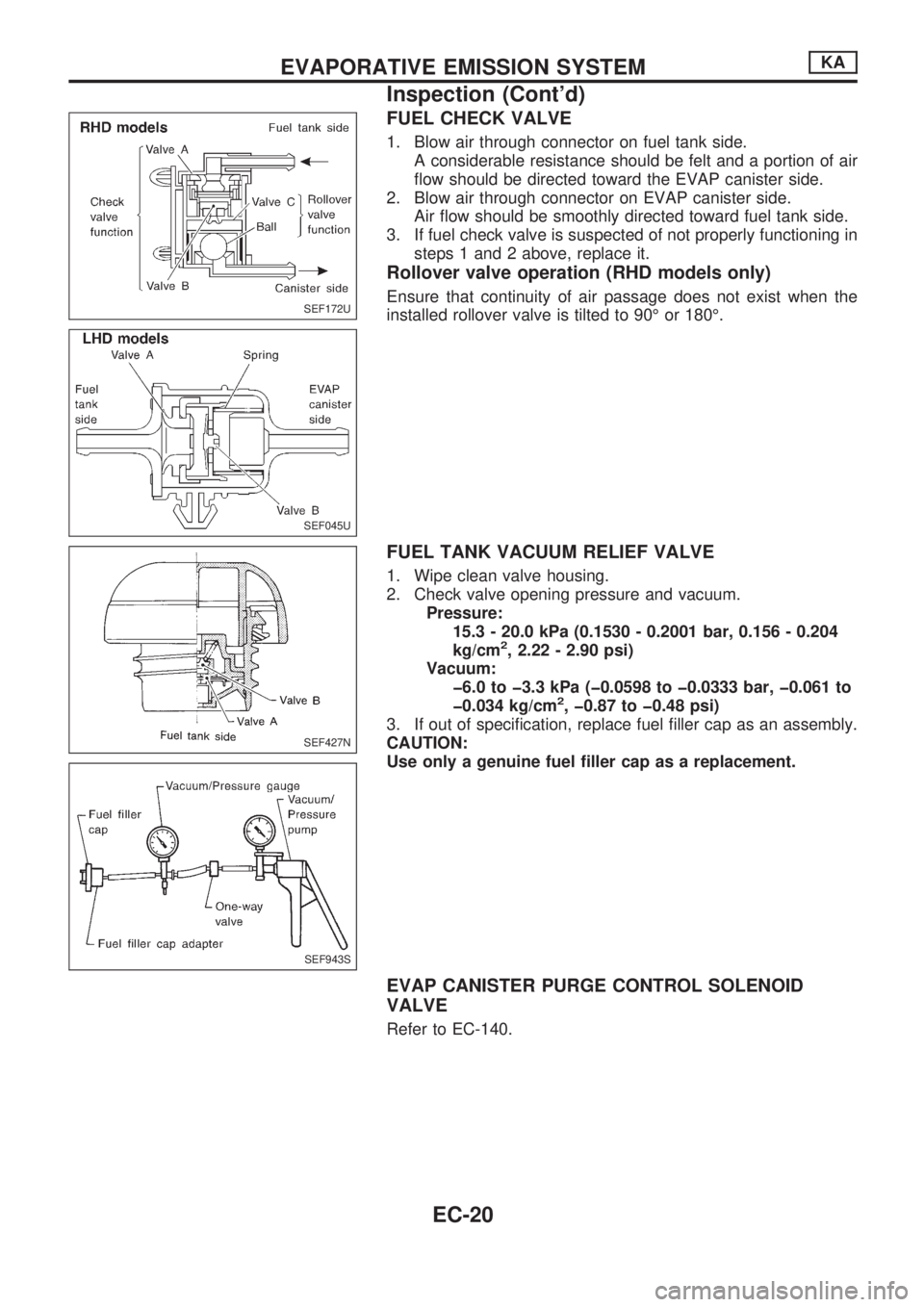
1. Blow air through connector on fuel tank side.
A considerable resistance should be felt and a portion of air
flow should be directed toward the EVAP canister side.
2. Blow air through connector on EVAP canister side.
Air flow should be smoothly directed toward fuel tank side.
3. If fuel check valve is suspected of not properly functioning in
steps 1 and 2 above, replace it.
Rollover valve operation (RHD models only)
Ensure that continuity of air passage does not exist when the
installed rollover valve is tilted to 90É or 180É.
FUEL TANK VACUUM RELIEF VALVE
1. Wipe clean valve housing.
2. Check valve opening pressure and vacuum.
Pressure:
15.3 - 20.0 kPa (0.1530 - 0.2001 bar, 0.156 - 0.204
kg/cm
2, 2.22 - 2.90 psi)
Vacuum:
þ6.0 to þ3.3 kPa (þ0.0598 to þ0.0333 bar, þ0.061 to
þ0.034 kg/cm
2, þ0.87 to þ0.48 psi)
3. If out of specification, replace fuel filler cap as an assembly.
CAUTION:
Use only a genuine fuel filler cap as a replacement.
EVAP CANISTER PURGE CONTROL SOLENOID
VALVE
Refer to EC-140.
SEF172U
SEF045U
SEF427N
SEF943S
EVAPORATIVE EMISSION SYSTEMKA
Inspection (Cont'd)
EC-20
Page 174 of 1659
Fuel Pressure Release
Before disconnecting fuel line, release fuel pressure from
fuel line to eliminate danger.
1. Start engine.
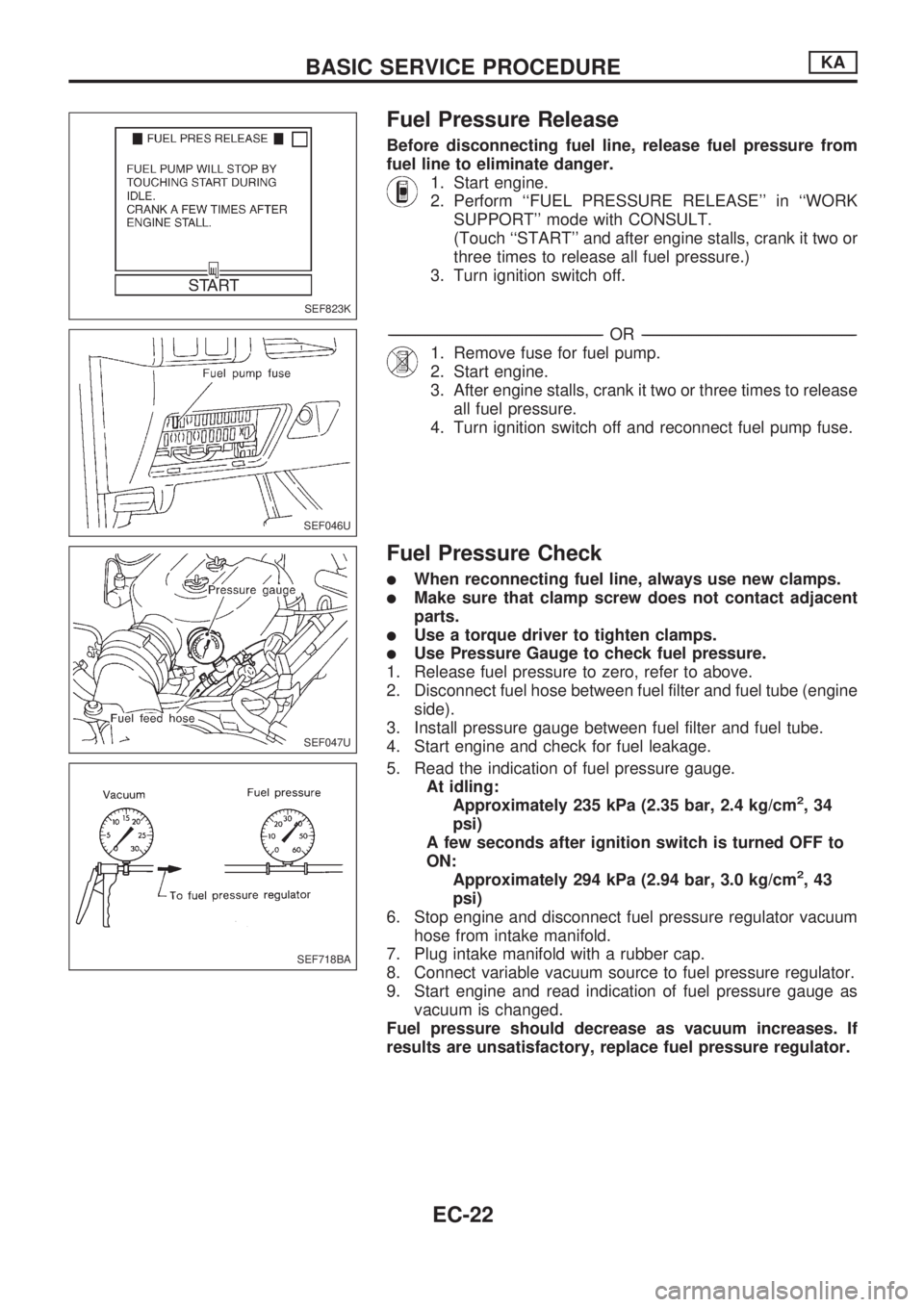
2. Perform ``FUEL PRESSURE RELEASE'' in ``WORK
SUPPORT'' mode with CONSULT.
(Touch ``START'' and after engine stalls, crank it two or
three times to release all fuel pressure.)
3. Turn ignition switch off.
-------------------------------------------------------------------------------------------------------------------------------------------------------------------------------------------------------------------------------------------------OR-------------------------------------------------------------------------------------------------------------------------------------------------------------------------------------------------------------------------------------------------
1. Remove fuse for fuel pump.
2. Start engine.
3. After engine stalls, crank it two or three times to release
all fuel pressure.
4. Turn ignition switch off and reconnect fuel pump fuse.
Fuel Pressure Check
lWhen reconnecting fuel line, always use new clamps.
lMake sure that clamp screw does not contact adjacent
parts.
lUse a torque driver to tighten clamps.
lUse Pressure Gauge to check fuel pressure.
1. Release fuel pressure to zero, refer to above.
2. Disconnect fuel hose between fuel filter and fuel tube (engine
side).
3. Install pressure gauge between fuel filter and fuel tube.
4. Start engine and check for fuel leakage.
5. Read the indication of fuel pressure gauge.
At idling:
Approximately 235 kPa (2.35 bar, 2.4 kg/cm
2,34
psi)
A few seconds after ignition switch is turned OFF to
ON:
Approximately 294 kPa (2.94 bar, 3.0 kg/cm
2,43
psi)
6. Stop engine and disconnect fuel pressure regulator vacuum
hose from intake manifold.
7. Plug intake manifold with a rubber cap.
8. Connect variable vacuum source to fuel pressure regulator.
9. Start engine and read indication of fuel pressure gauge as
vacuum is changed.
Fuel pressure should decrease as vacuum increases. If
results are unsatisfactory, replace fuel pressure regulator.
SEF823K
SEF046U
SEF047U
SEF718BA
BASIC SERVICE PROCEDUREKA
EC-22
Page 177 of 1659
Idle Speed/Ignition Timing/Idle Mixture Ratio
Adjustment
PREPARATION
lMake sure that the following parts are in
good order.
(1) Battery
(2) Ignition system
(3) Engine oil and coolant levels
(4) Fuses
(5) ECM harness connector
(6) Vacuum hoses
(7) Air intake system
(Oil filler cap, oil level gauge, etc.)
(8) Fuel pressure(9) Engine compression
(10) Throttle valvelOn air conditioner equipped models,
checks should be carried out while the air
conditioner is ``OFF''.
lWhen measuring ``CO'' percentage, insert
probe more than 40 cm (15.7 in) into tail
pipe.
lTurn off headlamps, heater blower, rear
window defogger.
lKeep front wheels pointed straight ahead.
LHD MODELS
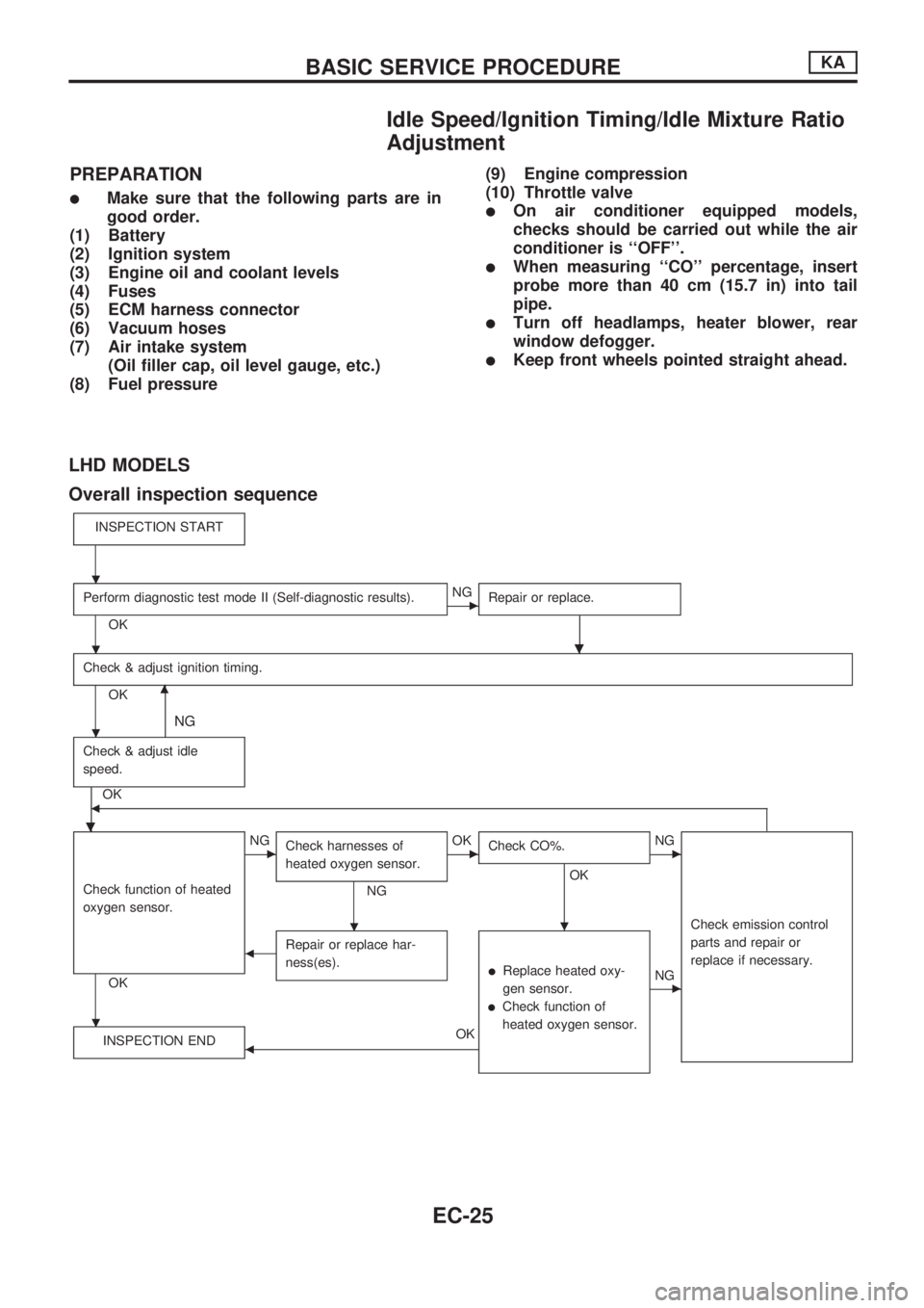
Overall inspection sequence
INSPECTION START
Perform diagnostic test mode II (Self-diagnostic results).
OK
cNG
Repair or replace.
.
Check & adjust ignition timing.
OKm
NG
Check & adjust idle
speed.
.
OKb
Check function of heated
oxygen sensor.
OK
cNG
Check harnesses of
heated oxygen sensor.
NG
cOK
Check CO%.
OK
.
cNG
Check emission control
parts and repair or
replace if necessary.
bRepair or replace har-
ness(es).
lReplace heated oxy-
gen sensor.
lCheck function of
heated oxygen sensor.
cNG
INSPECTION END
bOK
.
.
.
.
.
BASIC SERVICE PROCEDUREKA
EC-25
Page 207 of 1659
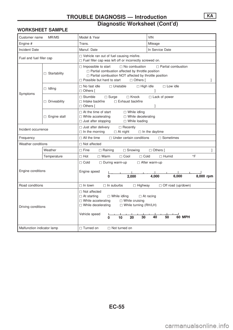
WORKSHEET SAMPLE
Customer name MR/MS Model & Year VIN
Engine # Trans. Mileage
Incident Date Manuf. Date In Service Date
Fuel and fuel filler caphVehicle ran out of fuel causing misfire.
hFuel filler cap was left off or incorrectly screwed on.
SymptomshStartabilityhImpossible to starthNo combustionhPartial combustion
hPartial combustion affected by throttle position
hPartial combustion NOT affected by throttle position
hPossible but hard to starthOthers [ ]
hIdlinghNo fast idlehUnstablehHigh idlehLow idle
hOthers [ ]
hDriveabilityhStumblehSurgehKnockhLack of power
hIntake backfirehExhaust backfire
hOthers [ ]
hEngine stallhAt the time of starthWhile idling
hWhile acceleratinghWhile decelerating
hJust after stoppinghWhile loading
Incident occurrencehJust after deliveryhRecently
hIn the morninghAt nighthIn the daytime
FrequencyhAll the timehUnder certain conditionshSometimes
Weather conditionshNot affected
WeatherhFinehRaininghSnowinghOthers [ ]
TemperaturehHothWarmhCoolhColdhHumid ÉF
Engine conditionshColdhDuring warm-uphAfter warm-up
Engine speed
Road conditionshIn townhIn suburbshHighwayhOff road (up/down)
Driving conditionshNot affected
hAt startinghWhile idlinghAt racing
hWhile acceleratinghWhile cruising
hWhile deceleratinghWhile turning (RH/LH)
Vehicle speed
Malfunction indicator lamphTurned onhNot turned on
TROUBLE DIAGNOSIS Ð IntroductionKA
Diagnostic Worksheet (Cont'd)
EC-55
Page 215 of 1659
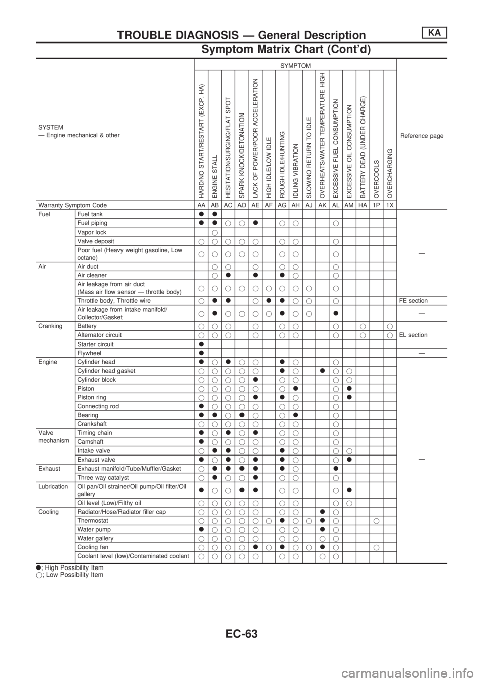
SYSTEM
Ð Engine mechanical & otherSYMPTOM
Reference page
HARD/NO START/RESTART (EXCP. HA)
ENGINE STALL
HESITATION/SURGING/FLAT SPOT
SPARK KNOCK/DETONATION
LACK OF POWER/POOR ACCELERATION
HIGH IDLE/LOW IDLE
ROUGH IDLE/HUNTING
IDLING VIBRATION
SLOW/NO RETURN TO IDLE
OVERHEATS/WATER TEMPERATURE HIGH
EXCESSIVE FUEL CONSUMPTION
EXCESSIVE OIL CONSUMPTION
BATTERY DEAD (UNDER CHARGE)
OVERCOOLS
OVERCHARGING
Warranty Symptom Code AA AB AC AD AE AF AG AH AJ AK AL AM HA 1P 1X
Fuel Fuel tank
ll
Ð Fuel piping
lljjljj j
Vapor lockj
Valve depositjjjjj jj j
Poor fuel (Heavy weight gasoline, Low
octane)jjjjj jj j
Air Air ductjjjjj j
Air cleanerj
llljj
Air leakage from air duct
(Mass air flow sensor Ð throttle body)jjjjjjjjj j
Throttle body, Throttle wirej
lljlljj jFE section
Air leakage from intake manifold/
Collector/Gasketj
ljjjjljjlÐ
Cranking Batteryjjjjjj jjj
EL section Alternator circuitjjjjjj jjj
Starter circuit
l
FlywheellÐ
Engine Cylinder head
ljljjljj
Ð Cylinder head gasketjjjjj
ljljj
Cylinder blockjjjj
ljj jj
Pistonjjjjj j
ljl
Piston ringjjjjlljjl
Connecting rodljjjj jj j
Bearing
lljljjlj
Crankshaftjjjjj jj j
Valve
mechanismTiming chain
ljljljj j
Camshaft
ljjjj jj j
Intake valvej
lljjljjj
Exhaust valve
ljljlljjl
Exhaust Exhaust manifold/Tube/Muffler/Gasketjllll ljl
Three way catalystjljjljj j
Lubrication Oil pan/Oil strainer/Oil pump/Oil filter/Oil
gallery
ljjlljj jl
Oil level (Low)/Filthy oiljjjjj jj jj
Cooling Radiator/Hose/Radiator filler capjjjjj jj
lj
Thermostatjjjjjj
ljjljj
Water pump
ljjjj jjlj
Water galleryjjjjj jj jj
Cooling fanjjjj
ljljjljj
Coolant level (low)/Contaminated coolantjjjjj jj jj
l; High Possibility Item
j; Low Possibility Item
TROUBLE DIAGNOSIS Ð General DescriptionKA
Symptom Matrix Chart (Cont'd)
EC-63
Page 234 of 1659
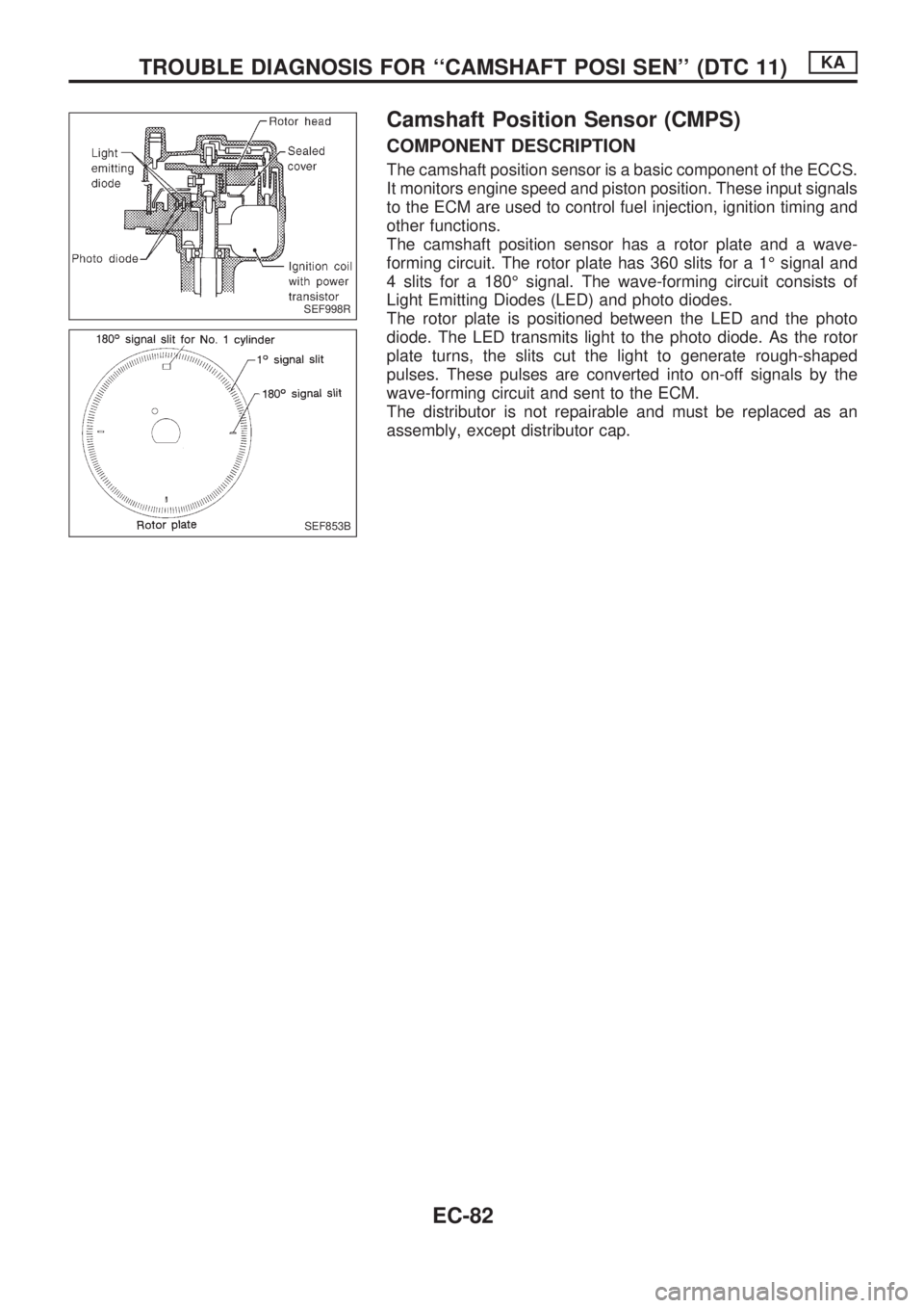
Camshaft Position Sensor (CMPS)
COMPONENT DESCRIPTION
The camshaft position sensor is a basic component of the ECCS.
It monitors engine speed and piston position. These input signals
to the ECM are used to control fuel injection, ignition timing and
other functions.
The camshaft position sensor has a rotor plate and a wave-
forming circuit. The rotor plate has 360 slits for a 1É signal and
4 slits for a 180É signal. The wave-forming circuit consists of
Light Emitting Diodes (LED) and photo diodes.
The rotor plate is positioned between the LED and the photo
diode. The LED transmits light to the photo diode. As the rotor
plate turns, the slits cut the light to generate rough-shaped
pulses. These pulses are converted into on-off signals by the
wave-forming circuit and sent to the ECM.
The distributor is not repairable and must be replaced as an
assembly, except distributor cap.
SEF998R
SEF853B
TROUBLE DIAGNOSIS FOR ``CAMSHAFT POSI SEN'' (DTC 11)KA
EC-82
Page 439 of 1659
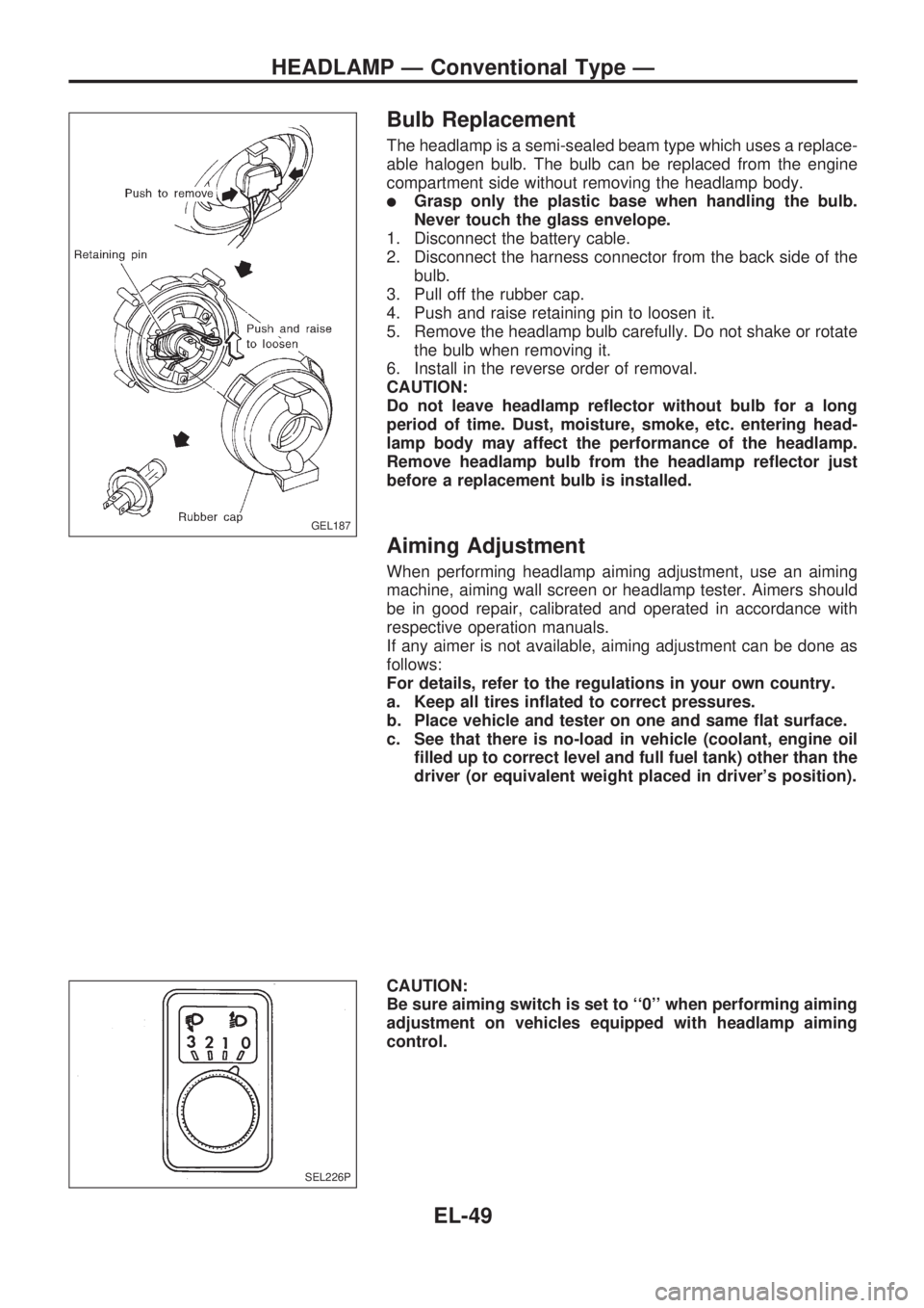
Bulb Replacement
The headlamp is a semi-sealed beam type which uses a replace-
able halogen bulb. The bulb can be replaced from the engine
compartment side without removing the headlamp body.
lGrasp only the plastic base when handling the bulb.
Never touch the glass envelope.
1. Disconnect the battery cable.
2. Disconnect the harness connector from the back side of the
bulb.
3. Pull off the rubber cap.
4. Push and raise retaining pin to loosen it.
5. Remove the headlamp bulb carefully. Do not shake or rotate
the bulb when removing it.
6. Install in the reverse order of removal.
CAUTION:
Do not leave headlamp reflector without bulb for a long
period of time. Dust, moisture, smoke, etc. entering head-
lamp body may affect the performance of the headlamp.
Remove headlamp bulb from the headlamp reflector just
before a replacement bulb is installed.
Aiming Adjustment
When performing headlamp aiming adjustment, use an aiming
machine, aiming wall screen or headlamp tester. Aimers should
be in good repair, calibrated and operated in accordance with
respective operation manuals.
If any aimer is not available, aiming adjustment can be done as
follows:
For details, refer to the regulations in your own country.
a. Keep all tires inflated to correct pressures.
b. Place vehicle and tester on one and same flat surface.
c. See that there is no-load in vehicle (coolant, engine oil
filled up to correct level and full fuel tank) other than the
driver (or equivalent weight placed in driver's position).
CAUTION:
Be sure aiming switch is set to ``0'' when performing aiming
adjustment on vehicles equipped with headlamp aiming
control.
GEL187
SEL226P
HEADLAMP Ð Conventional Type Ð
EL-49