Page 31 of 1659
Removal
WARNING:
Clean brake lining with a vacuum dust collector to minimize
the hazard of airborne materials.
CAUTION:
Make sure parking brake lever is completely released.
1. Release parking brake lever fully, then remove drum.
lIf drum is hard to remove, the following procedures
should be carried out.
a. Remove plug. Then shorten adjuster to make clearance
between brake shoe and drum.
b. Install two bolts as shown. Tighten the two bolts gradu-
ally.
2. After removing retainer, remove spring by rotating shoes.
lBe careful not to damage wheel cylinder piston boots.
lBe careful not to damage parking brake cable when
separating it.
3. Remove adjuster.
4. Disconnect parking brake cable from toggle lever.
5. Remove retainer clip with a suitable tool. Then separate
toggle lever and brake shoe.
SBR280B
SBR093A
ABR369
ABR408
REAR DRUM BRAKE
BR-27
Page 98 of 1659
INSTALLATION
lApply recommended grease to contact surface of spline por-
tion.
Too much lubricant might cause clutch disc facing damage.
Clutch Cover
INSPECTION
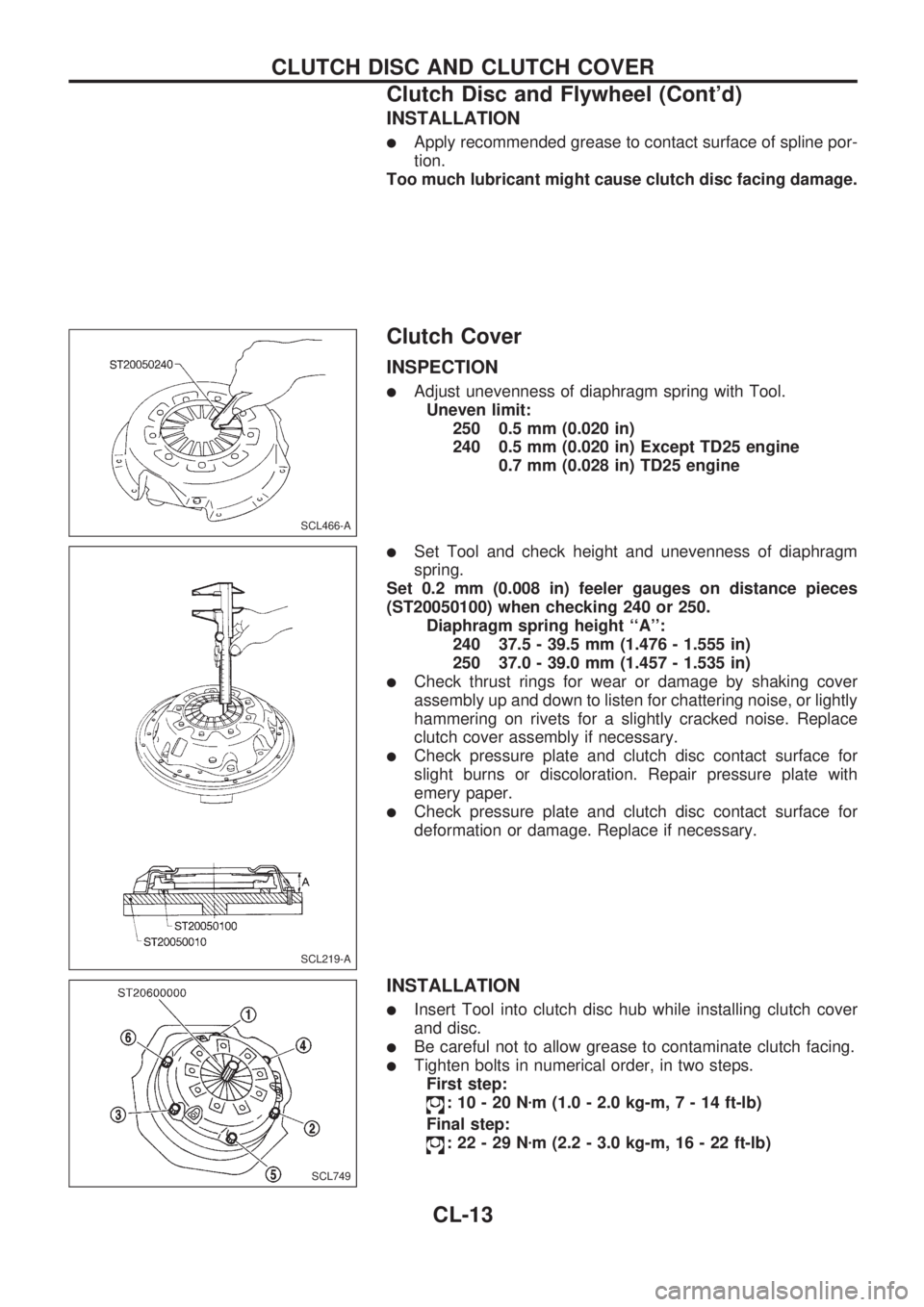
lAdjust unevenness of diaphragm spring with Tool.
Uneven limit:
250 0.5 mm (0.020 in)
240 0.5 mm (0.020 in) Except TD25 engine
0.7 mm (0.028 in) TD25 engine
lSet Tool and check height and unevenness of diaphragm
spring.
Set 0.2 mm (0.008 in) feeler gauges on distance pieces
(ST20050100) when checking 240 or 250.
Diaphragm spring height ``A'':
240 37.5 - 39.5 mm (1.476 - 1.555 in)
250 37.0 - 39.0 mm (1.457 - 1.535 in)
lCheck thrust rings for wear or damage by shaking cover
assembly up and down to listen for chattering noise, or lightly
hammering on rivets for a slightly cracked noise. Replace
clutch cover assembly if necessary.
lCheck pressure plate and clutch disc contact surface for
slight burns or discoloration. Repair pressure plate with
emery paper.
lCheck pressure plate and clutch disc contact surface for
deformation or damage. Replace if necessary.
INSTALLATION
lInsert Tool into clutch disc hub while installing clutch cover
and disc.
lBe careful not to allow grease to contaminate clutch facing.
lTighten bolts in numerical order, in two steps.
First step:
:10-20Nzm (1.0 - 2.0 kg-m,7-14ft-lb)
Final step:
:22-29Nzm (2.2 - 3.0 kg-m, 16 - 22 ft-lb)
SCL466-A
SCL219-A
SCL749
CLUTCH DISC AND CLUTCH COVER
Clutch Disc and Flywheel (Cont'd)
CL-13
Page 112 of 1659
CAUTION:
lDisconnect both terminals from battery in advance.
lDisconnect air bag module connector in advance.
lBe careful not to scratch finishers and other parts.
lNever tamper with or force air bag lid open, as this may adversely affect air bag performance.
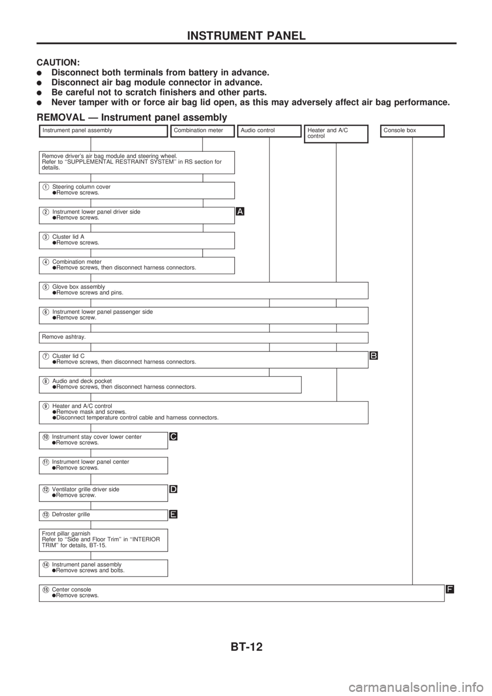
REMOVAL Ð Instrument panel assembly
Instrument panel assemblyCombination meterAudio controlHeater and A/C
controlConsole box
Remove driver's air bag module and steering wheel.
Refer to ``SUPPLEMENTAL RESTRAINT SYSTEM'' in RS section for
details.
V1Steering column coverlRemove screws.
V2Instrument lower panel driver sidelRemove screws.
V3Cluster lid AlRemove screws.
V4Combination meterlRemove screws, then disconnect harness connectors.
V5Glove box assemblylRemove screws and pins.
V6Instrument lower panel passenger sidelRemove screw.
Remove ashtray.
V7Cluster lid ClRemove screws, then disconnect harness connectors.
V8Audio and deck pocketlRemove screws, then disconnect harness connectors.
V9Heater and A/C controllRemove mask and screws.lDisconnect temperature control cable and harness connectors.
V10Instrument stay cover lower centerlRemove screws.
V11Instrument lower panel centerlRemove screws.
V12Ventilator grille driver sidelRemove screw.
V13Defroster grille
Front pillar garnish
Refer to ``Side and Floor Trim'' in ``INTERIOR
TRIM'' for details, BT-15.
V14Instrument panel assemblylRemove screws and bolts.
V15Center consolelRemove screws.
INSTRUMENT PANEL
BT-12
Page 681 of 1659
WARNING:
lPosition vehicle on a flat and solid surface.
lPlace chocks at front and back of rear wheels.
lDo not remove engine until exhaust system has com-
pletely cooled off.
Otherwise, you may burn yourself and/or fire may break
out in fuel line.
lBefore disconnecting fuel hose, release fuel pressure.
Refer to EC section (``Fuel Pressure Release'').
lBe sure to hoist engine and transmission in a safe man-
ner.
lFor engines not equipped with engine slingers, attach
proper slingers and bolts described in PARTS CATA-
LOG.
CAUTION:
lWhen lifting engine, be sure to clear surrounding parts.
Take special care near accelerator wire casing, brake
lines and brake master cylinder.
lIn lifting the engine, always use engine slingers in a safe
manner.
lFor 4WD models, apply sealant between engine and
transmission. Refer to MT section (``Removal and Instal-
lation'').
SEM601FA
ENGINE REMOVALKA
EM-36
Page 684 of 1659
CAUTION:
lWhen installing sliding parts (bearings, pistons, etc.),
lubricate contacting surfaces with new engine oil.
lPlace removed parts such as bearings and bearing caps
in their proper order and direction.
lWhen installing connecting rod nuts and main bearing
cap bolts, apply new engine oil to threads and seating
surfaces.
lDo not allow any magnetic materials to contact the ring
gear teeth of flywheel or drive plate.
Disassembly
PISTON AND CRANKSHAFT
1. Remove intake manifold.
2. Place engine on a work stand.
3. Drain coolant and oil.
4. Remove oil pan.
5. Remove water pump.
6. Remove timing chain.
7. Remove cylinder head.
8. Remove pistons with connecting rod.
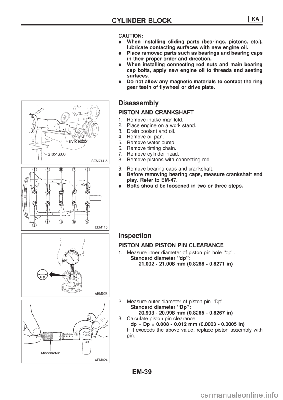
9. Remove bearing caps and crankshaft.
lBefore removing bearing caps, measure crankshaft end
play. Refer to EM-47.
lBolts should be loosened in two or three steps.
Inspection
PISTON AND PISTON PIN CLEARANCE
1. Measure inner diameter of piston pin hole ``dp''.
Standard diameter ``dp'':
21.002 - 21.008 mm (0.8268 - 0.8271 in)
2. Measure outer diameter of piston pin ``Dp''.
Standard diameter ``Dp'':
20.993 - 20.998 mm (0.8265 - 0.8267 in)
3. Calculate piston pin clearance.
dp þ Dp = 0.008 - 0.012 mm (0.0003 - 0.0005 in)
If it exceeds the above value, replace piston assembly with
pin.
SEM744-A
EEM118
AEM023
AEM024
CYLINDER BLOCKKA
EM-39
Page 697 of 1659
Removal
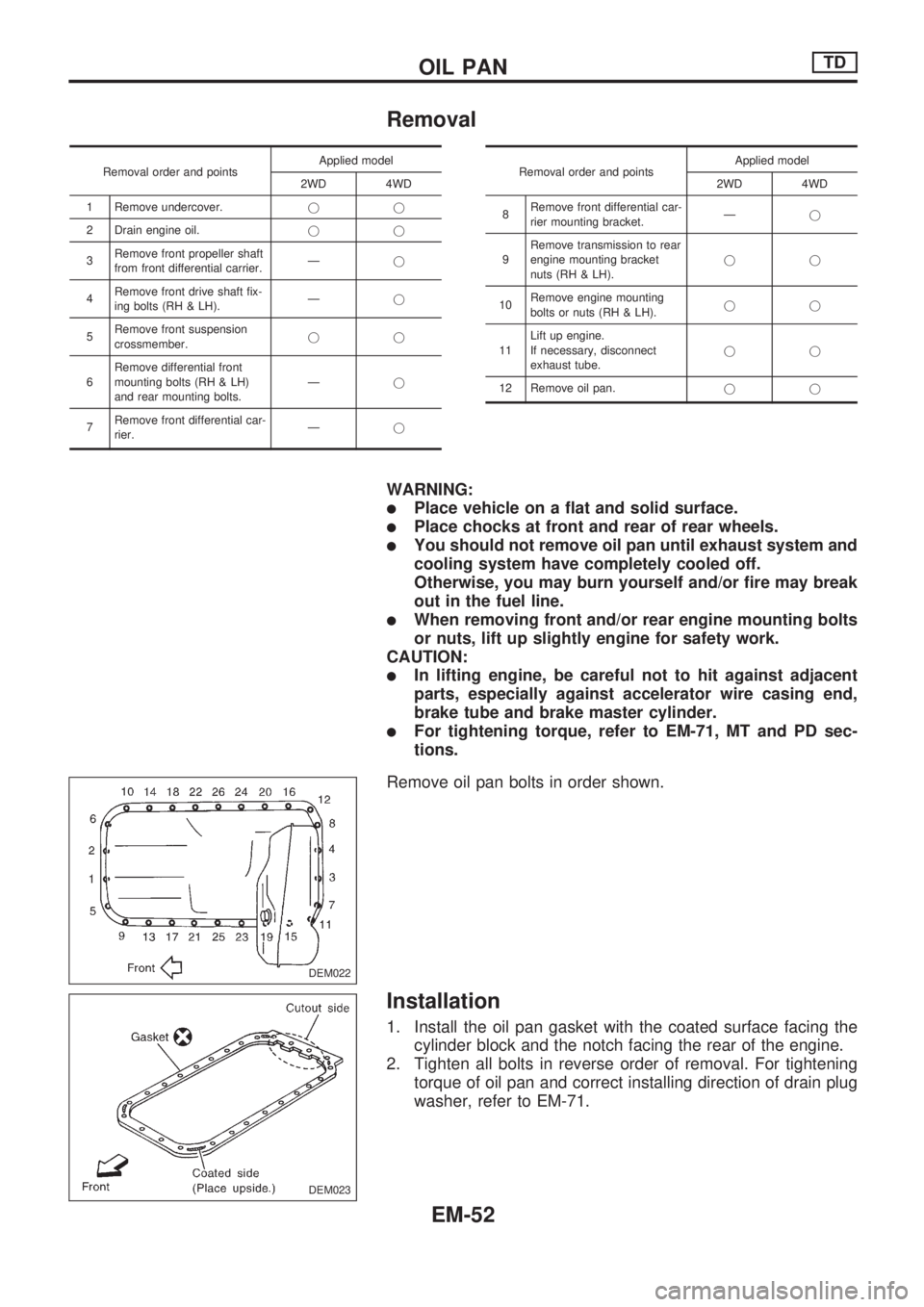
Removal order and pointsApplied model
2WD 4WD
1 Remove undercover.jj
2 Drain engine oil.jj
3Remove front propeller shaft
from front differential carrier.Ðj
4Remove front drive shaft fix-
ing bolts (RH & LH).Ðj
5Remove front suspension
crossmember.jj
6Remove differential front
mounting bolts (RH & LH)
and rear mounting bolts.Ðj
7Remove front differential car-
rier.ÐjRemoval order and pointsApplied model
2WD 4WD
8Remove front differential car-
rier mounting bracket.Ðj
9Remove transmission to rear
engine mounting bracket
nuts (RH & LH).jj
10Remove engine mounting
bolts or nuts (RH & LH).jj
11Lift up engine.
If necessary, disconnect
exhaust tube.jj
12 Remove oil pan.jj
WARNING:
lPlace vehicle on a flat and solid surface.
lPlace chocks at front and rear of rear wheels.
lYou should not remove oil pan until exhaust system and
cooling system have completely cooled off.
Otherwise, you may burn yourself and/or fire may break
out in the fuel line.
lWhen removing front and/or rear engine mounting bolts
or nuts, lift up slightly engine for safety work.
CAUTION:
lIn lifting engine, be careful not to hit against adjacent
parts, especially against accelerator wire casing end,
brake tube and brake master cylinder.
lFor tightening torque, refer to EM-71, MT and PD sec-
tions.
Remove oil pan bolts in order shown.
Installation
1. Install the oil pan gasket with the coated surface facing the
cylinder block and the notch facing the rear of the engine.
2. Tighten all bolts in reverse order of removal. For tightening
torque of oil pan and correct installing direction of drain plug
washer, refer to EM-71.
DEM022
DEM023
OIL PANTD
EM-52
Page 714 of 1659
WARNING:
lPosition vehicle on a flat and solid surface.
lPlace chocks at front and back of rear wheels.
lDo not remove engine until exhaust system has com-
pletely cooled off.
Otherwise, you may burn yourself and/or fire may break
out in fuel line.
lBe sure to hoist engine and transmission in a safe man-
ner.
lFor engines not equipped with engine slingers, attach
proper slingers and bolts described in PARTS CATA-
LOG.
CAUTION:
lWhen lifting engine, be sure to clear surrounding parts.
Take special care near accelerator wire casing, brake
lines and brake master cylinder.
lIn lifting the engine, always use engine slingers in a safe
manner.
lFor 4WD models, apply sealant between engine and
transmission. Refer to MT section (``Removal and Instal-
lation'').
SEM613FN
ENGINE REMOVALTD
EM-69
Page 770 of 1659
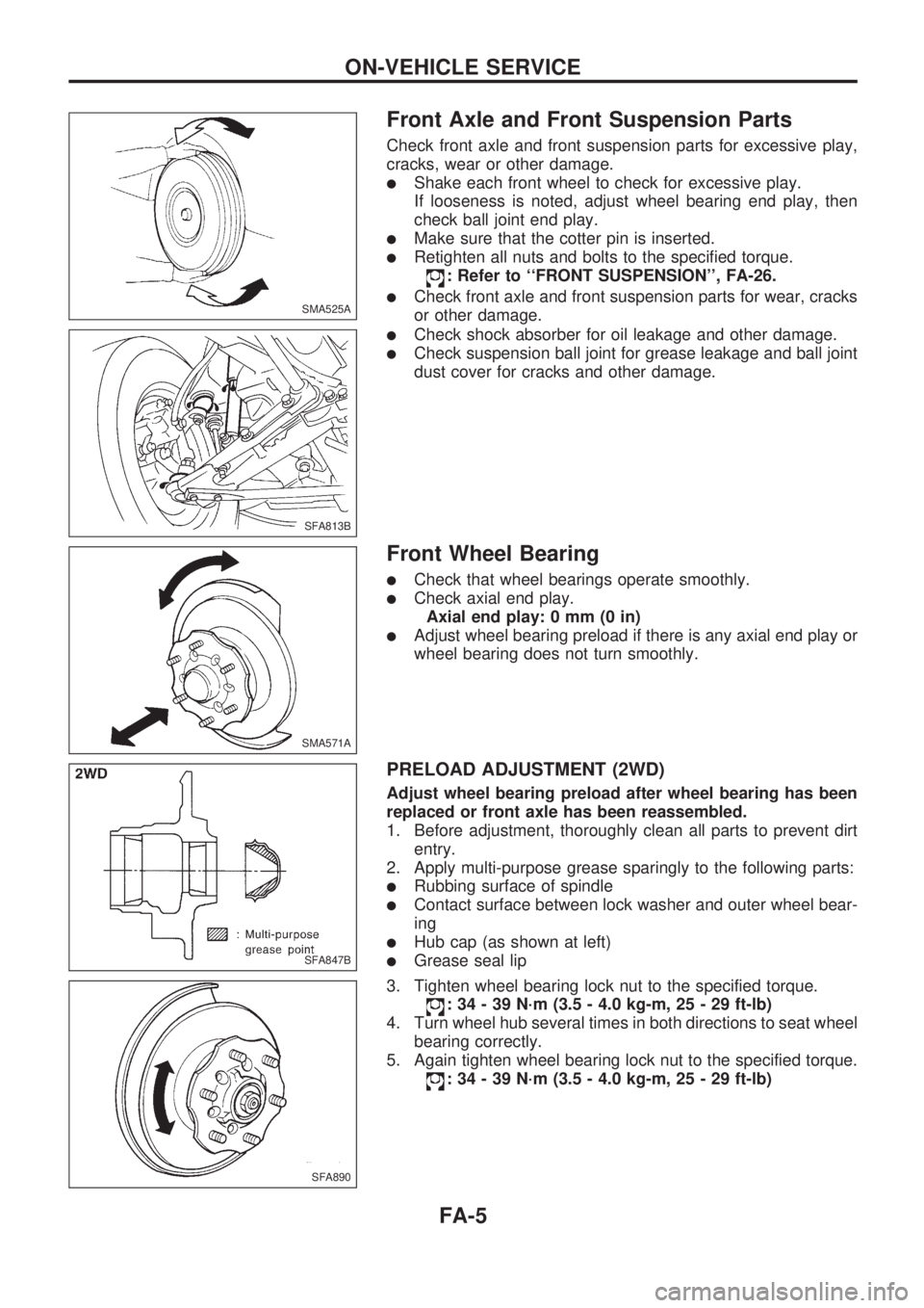
Front Axle and Front Suspension Parts
Check front axle and front suspension parts for excessive play,
cracks, wear or other damage.
lShake each front wheel to check for excessive play.
If looseness is noted, adjust wheel bearing end play, then
check ball joint end play.
lMake sure that the cotter pin is inserted.
lRetighten all nuts and bolts to the specified torque.
: Refer to ``FRONT SUSPENSION'', FA-26.
lCheck front axle and front suspension parts for wear, cracks
or other damage.
lCheck shock absorber for oil leakage and other damage.
lCheck suspension ball joint for grease leakage and ball joint
dust cover for cracks and other damage.
Front Wheel Bearing
lCheck that wheel bearings operate smoothly.
lCheck axial end play.
Axial end play: 0 mm (0 in)
lAdjust wheel bearing preload if there is any axial end play or
wheel bearing does not turn smoothly.
PRELOAD ADJUSTMENT (2WD)
Adjust wheel bearing preload after wheel bearing has been
replaced or front axle has been reassembled.
1. Before adjustment, thoroughly clean all parts to prevent dirt
entry.
2. Apply multi-purpose grease sparingly to the following parts:
lRubbing surface of spindle
lContact surface between lock washer and outer wheel bear-
ing
lHub cap (as shown at left)
lGrease seal lip
3. Tighten wheel bearing lock nut to the specified torque.
: 34 - 39 N´m (3.5 - 4.0 kg-m, 25 - 29 ft-lb)
4. Turn wheel hub several times in both directions to seat wheel
bearing correctly.
5. Again tighten wheel bearing lock nut to the specified torque.
: 34 - 39 N´m (3.5 - 4.0 kg-m, 25 - 29 ft-lb)
SMA525A
SFA813B
SMA571A
SFA847B
SFA890
ON-VEHICLE SERVICE
FA-5