Page 1210 of 1659
Rear Axle and Rear Suspension Parts
Check rear axle and rear suspension parts for excessive play,
wear or damage.
lShake each rear wheel to check for excessive play.
lRetighten all nuts and bolts to the specified torque.
: Refer to REAR SUSPENSION, RA-12..
lCheck shock absorber for oil leakage or other damage.
lCheck shock absorber bushing for excessive wear or other
damage.
Rear Wheel Bearing
lCheck that wheel bearings operate smoothly.
lCheck axial end play.
Axial end play:
Refer to SDS, RA-15.
SMA525A
SRA839
SRA734
SRA006-A
ON-VEHICLE SERVICE
RA-4
Page 1232 of 1659
![NISSAN PICK-UP 1998 Repair Manual 3. Remove steering wheel using Tool.
lFor installation, refer to RS section [``Air Bag Module and
Spiral Cable, ``SUPPLEMENTAL RESTRAINT SYSTEM
(SRS)].
Steering Column
REMOVAL
CAUTION:
lThe rotati NISSAN PICK-UP 1998 Repair Manual 3. Remove steering wheel using Tool.
lFor installation, refer to RS section [``Air Bag Module and
Spiral Cable, ``SUPPLEMENTAL RESTRAINT SYSTEM
(SRS)].
Steering Column
REMOVAL
CAUTION:
lThe rotati](/manual-img/5/57374/w960_57374-1231.png)
3. Remove steering wheel using Tool.
lFor installation, refer to RS section [``Air Bag Module and
Spiral Cable'', ``SUPPLEMENTAL RESTRAINT SYSTEM
(SRS)''].
Steering Column
REMOVAL
CAUTION:
lThe rotation of the spiral cable (SRS ``Air bag'' compo-
nent part) is limited. If the steering gear must be
removed, set the front wheels in the straight-ahead
direction.
Do not rotate the steering column while the steering gear
is removed.
lRemove the steering wheel before removing the steering
lower joint to avoid damaging the SRS spiral cable. Refer
to ST-9.
1. Remove steering wheel, refer to ST-9.
2. Remove steering column cover.
3. Remove instrument lower panel.
4. Disconnect combination switch electrical connectors and air
bag harness connector.
5. Remove dash insulator.
6. Remove bolt from lower joint.
7. Remove two steering column bolts and remove steering col-
umn.
INSTALLATION
lWhen installing steering column, finger-tighten all lower
bracket and clamp retaining bolts; then tighten them
securely. Make sure that undue stress is not applied to steer-
ing column.
lWhen fitting steering lower joint, be sure tightening bolt faces
cutout portion.
lAlign spiral cable correctly when installing steering wheel.
Refer to RS section [``Air Bag Module and Spiral Cable'',
``SUPPLEMENTAL RESTRAINT SYSTEM (SRS)''].
CAUTION:
After installation, turn steering wheel to make sure it moves
smoothly. Ensure the number of turns from the straight for-
ward position to left and right locks are the same. Be sure
that the steering wheel is in a neutral position when driving
straight ahead.
SST515B
SST666A
STEERING WHEEL AND STEERING COLUMN
Steering Wheel (Cont'd)
ST-10
Page 1589 of 1659
WARNING:
lPosition vehicle on a flat and solid surface.
lPlace chocks at front and back of rear wheels.
lDo not remove engine until exhaust system has com-
pletely cooled off.
Otherwise, you may burn yourself and/or fire may break
out in fuel line.
lBefore disconnecting fuel hose, release fuel pressure.
Refer to EC section (``Fuel Pressure Release'').
lBe sure to hoist engine and transmission in a safe man-
ner.
lFor engines not equipped with engine slingers, attach
proper slingers and bolts described in PARTS CATA-
LOG.
CAUTION:
lWhen lifting engine, be sure to clear surrounding parts.
Take special care near accelerator wire casing, brake
lines and brake master cylinder.
lIn lifting the engine, always use engine slingers in a safe
manner.
lFor 4WD models, apply sealant between engine and
transmission. Refer to MT section (``Removal and Instal-
lation'').
SEM601FA
ENGINE REMOVALKA
EM-36
Page 1592 of 1659

CAUTION:
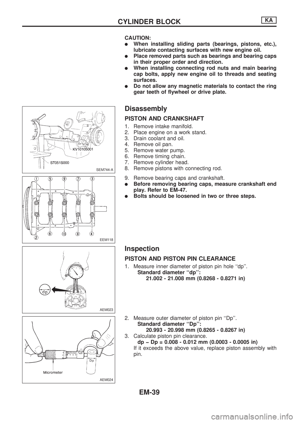
lWhen installing sliding parts (bearings, pistons, etc.),
lubricate contacting surfaces with new engine oil.
lPlace removed parts such as bearings and bearing caps
in their proper order and direction.
lWhen installing connecting rod nuts and main bearing
cap bolts, apply new engine oil to threads and seating
surfaces.
lDo not allow any magnetic materials to contact the ring
gear teeth of flywheel or drive plate.
Disassembly
PISTON AND CRANKSHAFT
1. Remove intake manifold.
2. Place engine on a work stand.
3. Drain coolant and oil.
4. Remove oil pan.
5. Remove water pump.
6. Remove timing chain.
7. Remove cylinder head.
8. Remove pistons with connecting rod.
9. Remove bearing caps and crankshaft.
lBefore removing bearing caps, measure crankshaft end
play. Refer to EM-47.
lBolts should be loosened in two or three steps.
Inspection
PISTON AND PISTON PIN CLEARANCE
1. Measure inner diameter of piston pin hole ``dp''.
Standard diameter ``dp'':
21.002 - 21.008 mm (0.8268 - 0.8271 in)
2. Measure outer diameter of piston pin ``Dp''.
Standard diameter ``Dp'':
20.993 - 20.998 mm (0.8265 - 0.8267 in)
3. Calculate piston pin clearance.
dp þ Dp = 0.008 - 0.012 mm (0.0003 - 0.0005 in)
If it exceeds the above value, replace piston assembly with
pin.
SEM744-A
EEM118
AEM023
AEM024
CYLINDER BLOCKKA
EM-39
Page 1605 of 1659

Removal
Removal order and pointsApplied model
2WD 4WD
1 Remove undercover.jj
2 Drain engine oil.jj
3Remove front propeller shaft
from front differential carrier.Ðj
4Remove front drive shaft fix-
ing bolts (RH & LH).Ðj
5Remove front suspension
crossmember.jj
6Remove differential front
mounting bolts (RH & LH)
and rear mounting bolts.Ðj
7Remove front differential car-
rier.ÐjRemoval order and pointsApplied model
2WD 4WD
8Remove front differential car-
rier mounting bracket.Ðj
9Remove transmission to rear
engine mounting bracket
nuts (RH & LH).jj
10Remove engine mounting
bolts or nuts (RH & LH).jj
11Lift up engine.
If necessary, disconnect
exhaust tube.jj
12 Remove oil pan.jj
WARNING:
lPlace vehicle on a flat and solid surface.
lPlace chocks at front and rear of rear wheels.
lYou should not remove oil pan until exhaust system and
cooling system have completely cooled off.
Otherwise, you may burn yourself and/or fire may break
out in the fuel line.
lWhen removing front and/or rear engine mounting bolts
or nuts, lift up slightly engine for safety work.
CAUTION:
lIn lifting engine, be careful not to hit against adjacent
parts, especially against accelerator wire casing end,
brake tube and brake master cylinder.
lFor tightening torque, refer to EM-71, MT and PD sec-
tions.
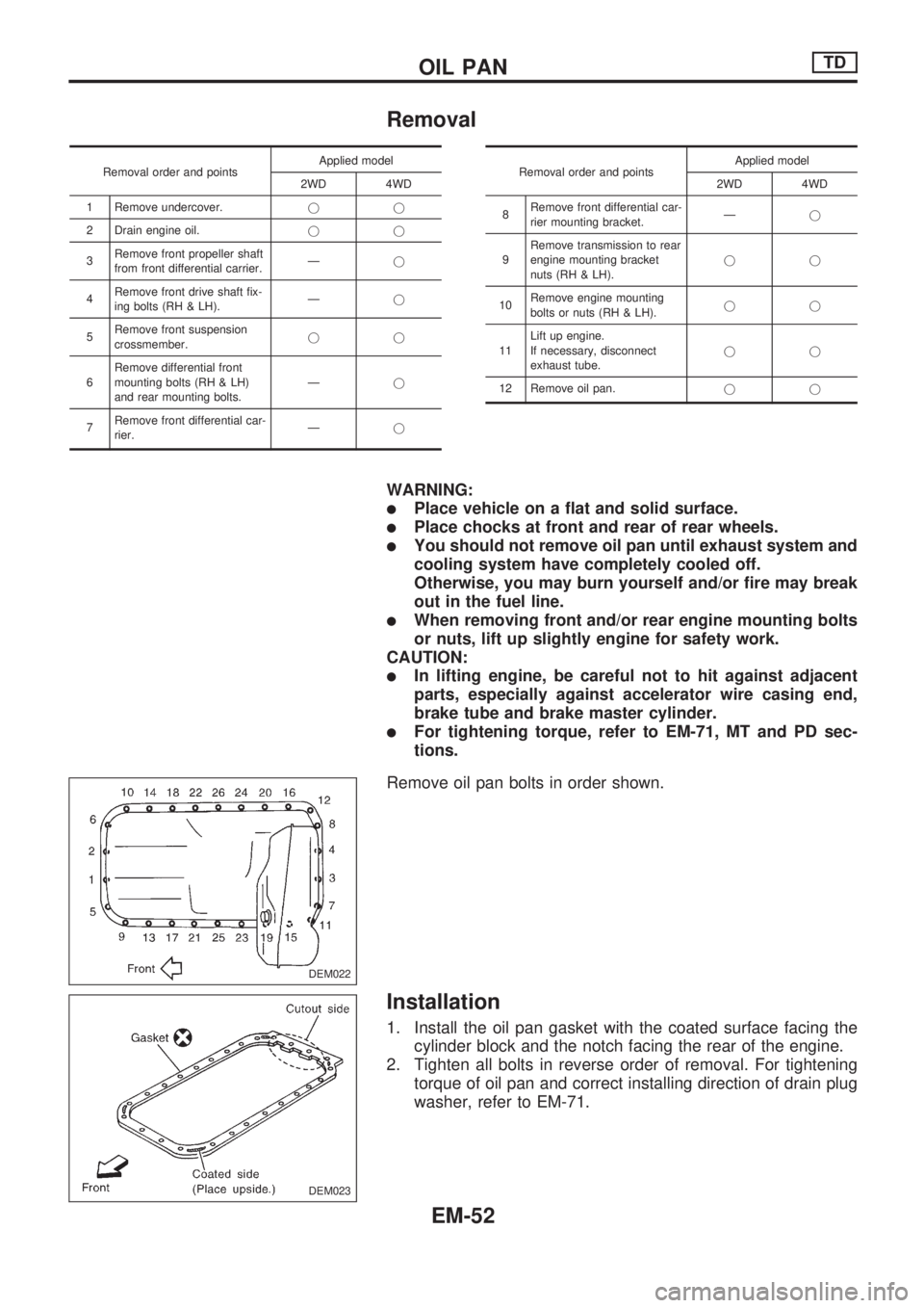
Remove oil pan bolts in order shown.
Installation
1. Install the oil pan gasket with the coated surface facing the
cylinder block and the notch facing the rear of the engine.
2. Tighten all bolts in reverse order of removal. For tightening
torque of oil pan and correct installing direction of drain plug
washer, refer to EM-71.
DEM022
DEM023
OIL PANTD
EM-52
Page 1622 of 1659
WARNING:
lPosition vehicle on a flat and solid surface.
lPlace chocks at front and back of rear wheels.
lDo not remove engine until exhaust system has com-
pletely cooled off.
Otherwise, you may burn yourself and/or fire may break
out in fuel line.
lBe sure to hoist engine and transmission in a safe man-
ner.
lFor engines not equipped with engine slingers, attach
proper slingers and bolts described in PARTS CATA-
LOG.
CAUTION:
lWhen lifting engine, be sure to clear surrounding parts.
Take special care near accelerator wire casing, brake
lines and brake master cylinder.
lIn lifting the engine, always use engine slingers in a safe
manner.
lFor 4WD models, apply sealant between engine and
transmission. Refer to MT section (``Removal and Instal-
lation'').
SEM613FN
ENGINE REMOVALTD
EM-69