1998 NISSAN PICK-UP mirror
[x] Cancel search: mirrorPage 100 of 1659
BODY & TRIM
SECTIONBT
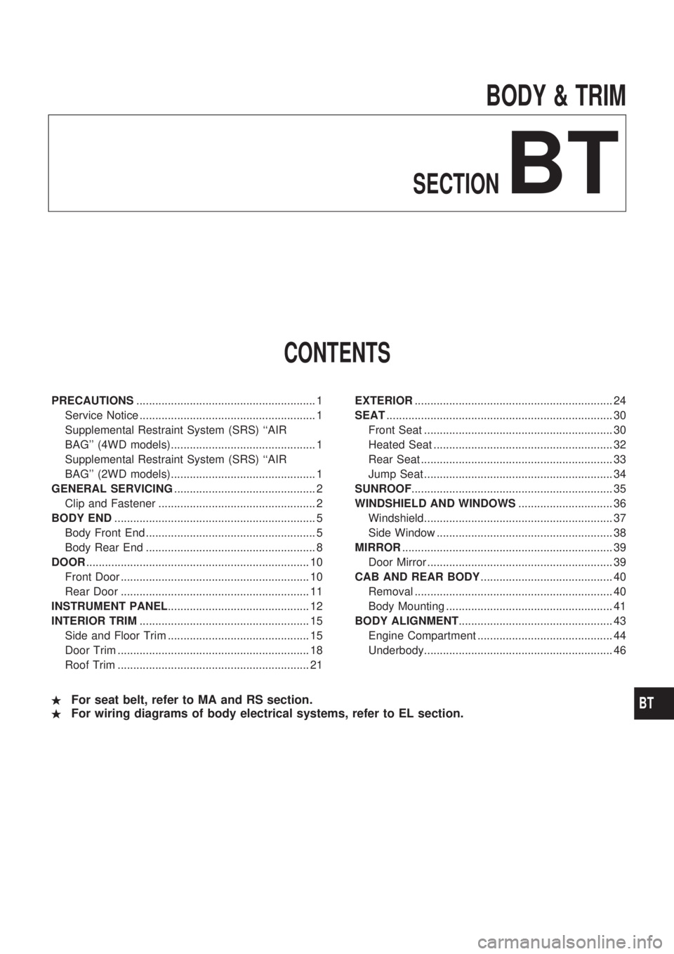
CONTENTS
PRECAUTIONS......................................................... 1
Service Notice ........................................................ 1
Supplemental Restraint System (SRS) ``AIR
BAG'' (4WD models).............................................. 1
Supplemental Restraint System (SRS) ``AIR
BAG'' (2WD models).............................................. 1
GENERAL SERVICING............................................. 2
Clip and Fastener .................................................. 2
BODY END................................................................ 5
Body Front End ...................................................... 5
Body Rear End ...................................................... 8
DOOR....................................................................... 10
Front Door ............................................................ 10
Rear Door ............................................................ 11
INSTRUMENT PANEL............................................. 12
INTERIOR TRIM...................................................... 15
Side and Floor Trim ............................................. 15
Door Trim ............................................................. 18
Roof Trim ............................................................. 21EXTERIOR............................................................... 24
SEAT........................................................................ 30
Front Seat ............................................................ 30
Heated Seat ......................................................... 32
Rear Seat ............................................................. 33
Jump Seat ............................................................ 34
SUNROOF................................................................ 35
WINDSHIELD AND WINDOWS.............................. 36
Windshield............................................................ 37
Side Window ........................................................ 38
MIRROR................................................................... 39
Door Mirror ........................................................... 39
CAB AND REAR BODY.......................................... 40
Removal ............................................................... 40
Body Mounting ..................................................... 41
BODY ALIGNMENT................................................. 43
Engine Compartment ........................................... 44
Underbody............................................................ 46
.For seat belt, refer to MA and RS section.
.For wiring diagrams of body electrical systems, refer to EL section.BT
Page 121 of 1659
Roof Trim
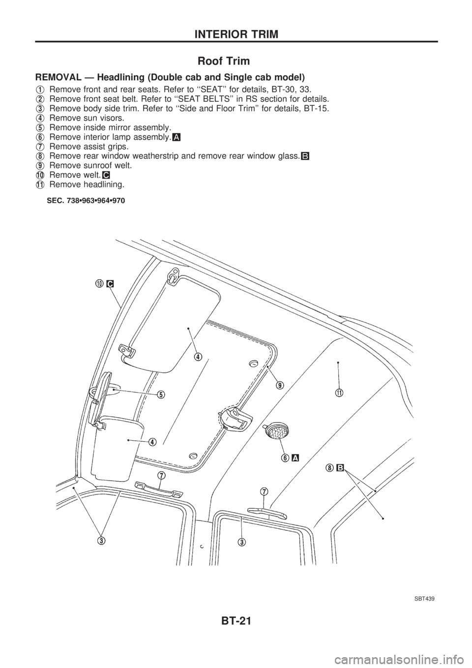
REMOVAL Ð Headlining (Double cab and Single cab model)
V1Remove front and rear seats. Refer to ``SEAT'' for details, BT-30, 33.
V2Remove front seat belt. Refer to ``SEAT BELTS'' in RS section for details.
V3Remove body side trim. Refer to ``Side and Floor Trim'' for details, BT-15.
V4Remove sun visors.
V5Remove inside mirror assembly.
V6Remove interior lamp assembly.
V7Remove assist grips.
V8Remove rear window weatherstrip and remove rear window glass.
V9Remove sunroof welt.
V10Remove welt.
V11Remove headlining.
SBT439
INTERIOR TRIM
BT-21
Page 123 of 1659
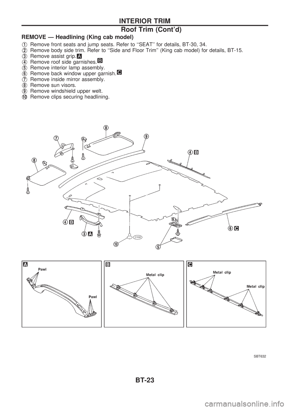
REMOVE Ð Headlining (King cab model)
V1Remove front seats and jump seats. Refer to ``SEAT'' for details, BT-30, 34.
V2Remove body side trim. Refer to ``Side and Floor Trim'' (King cab model) for details, BT-15.
V3Remove assist grip.
V4Remove roof side garnishes.
V5Remove interior lamp assembly.
V6Remove back window upper garnish.
V7Remove inside mirror assembly.
V8Remove sun visors.
V9Remove windshield upper welt.
V10Remove clips securing headlining.
SBT632
INTERIOR TRIM
Roof Trim (Cont'd)
BT-23
Page 139 of 1659

Door MirrorCAUTION:
Be careful not to scratch door rearview mirror body.
.For Wiring Diagram, refer to ``POWER DOOR MIRROR'' in EL section.
REMOVAL Ð Door mirror
V1Remove door trim. Refer to ``Door Trim'' for details, BT-18.
V2Remove inner cover from front corner of door.
V3Disconnect door mirror harness connector.
V4Remove bolts securing door mirror, then remove door mirror assembly.
SBT458
MIRROR
BT-39
Page 389 of 1659
HEADLAMP - Headlamp Aiming Control -........... 63
System Description .............................................. 63
Wiring Diagram - H/AIM - .................................... 64
PARKING, LICENSE AND TAIL LAMPS............... 66
Wiring Diagram - TAIL/L -/Except for LHD
Models for Europe ............................................... 66
Wiring Diagram - TAIL/L -/LHD Models for
Europe.................................................................. 68
STOP LAMP............................................................ 70
Wiring Diagram - STOP/L - ................................. 70
BACK-UP LAMP...................................................... 71
Wiring Diagram - BACK/L - ................................. 71
REAR FOG LAMP................................................... 72
Wiring Diagram - R/FOG -/LHD Models .............. 72
Wiring Diagram - R/FOG -/RHD Models ............. 73
TURN SIGNAL AND HAZARD WARNING
LAMPS..................................................................... 74
Schematic ............................................................ 74
Wiring Diagram - TURN -/Except 4WD Models
for Europe ............................................................ 75
Wiring Diagram - TURN -/4WD Models for
Europe.................................................................. 77
Trouble Diagnoses ............................................... 80
Combination Flasher Unit Check ......................... 80
ILLUMINATION........................................................ 81
Wiring Diagram - ILL -/LHD Models .................... 81
Wiring Diagram - ILL -/RHD Models.................... 83
INTERIOR AND SPOT LAMPS............................... 85
Wiring Diagram - INT/L - ..................................... 85
Combination Meter............................................... 87
Schematic ............................................................ 89
Wiring Diagram - METER -/LHD Models............. 90
Wiring Diagram - METER -/RHD Models ............ 93
Unified Control Meter System Description .......... 96
Meter/gauge Operation and Odo/Trip Meter
Segment Check in Diagnosis Mode .................... 96
Flexible Print Circuit (FPC) .................................. 97
Trouble Diagnoses ............................................... 98
Electrical Components Inspection ..................... 103
WARNING LAMPS................................................ 105
Schematic .......................................................... 105
Wiring Diagram - WARN -/LHD Models ............ 106
Wiring Diagram - WARN -/RHD Models............ 111
Electrical Components Inspection ..................... 116
WARNING BUZZER.............................................. 117
Wiring diagram - BUZZER -/LHD Models for
Europe................................................................ 117
Wiring diagram - BUZZER -/RHD Models for
Europe................................................................ 118
Electrical Components Inspection ..................... 119
FRONT WIPER AND WASHER............................ 120
System Description ............................................ 120
Wiring Diagram - WIPER -/LHD Models with
Intermittent ......................................................... 122Wiring Diagram - WIPER -/RHD Models with
Intermittent ......................................................... 124
Trouble Diagnoses ............................................. 126
Wiper Installation and Adjustment ..................... 127
Washer Nozzle Adjustment ............................... 128
Washer Tube Layout ......................................... 128
Wiper Linkage .................................................... 129
HEADLAMP WASHER.......................................... 130
Wiring Diagram - HLC - ..................................... 130
Trouble Diagnoses ............................................. 131
Washer Tube Layout ......................................... 131
Check Valve ....................................................... 131
HORN..................................................................... 132
Wiring Diagram - HORN -.................................. 132
CIGARETTE LIGHTER.......................................... 133
Wiring Diagram - CIGAR - ................................. 133
CLOCK................................................................... 134
Wiring Diagram - CLOCK - ................................ 134
REAR WINDOW DEFOGGER............................... 135
Wiring Diagram - DEF - ..................................... 135
Electrical Components Inspection ..................... 136
Filament Check .................................................. 136
Filament Repair.................................................. 137
AUDIO.................................................................... 138
Wiring Diagram - AUDIO -/LHD Models Type-
2 ......................................................................... 138
Wiring Diagram - AUDIO -/LHD Models Type-
3 ......................................................................... 139
Wiring Diagram - AUDIO -/RHD Models ........... 141
Trouble Diagnoses ............................................. 142
CATS (Code) System/For Europe RHD ............ 143
NATS Audio Link/For Europe LHD (KA24E) ..... 144
AUDIO ANTENNA................................................. 146
Manual Antenna ................................................. 146
Power Antenna/Wiring Diagram - P/ANT - ........ 147
Power Antenna .................................................. 148
POWER DOOR MIRROR...................................... 150
Wiring Diagram - MIRROR -.............................. 150
HEATED SEAT...................................................... 152
Wiring Diagram - H/SEAT - ............................... 152
POWER WINDOW................................................. 154
System Description ............................................ 154
Schematic .......................................................... 156
Wiring Diagram - WINDOW -/LHD Models ....... 157
Wiring Diagram - WINDOW -/RHD Models ....... 161
Trouble Diagnoses ............................................. 165
POWER DOOR LOCK........................................... 166
System Description ............................................ 166
Wiring Diagram - D/LOCK - ............................... 167
Trouble Diagnosis .............................................. 169
MULTI-REMOTE CONTROL SYSTEM/FOR
EUROPE................................................................ 173
System Description ............................................ 173
Schematic .......................................................... 174
Page 405 of 1659
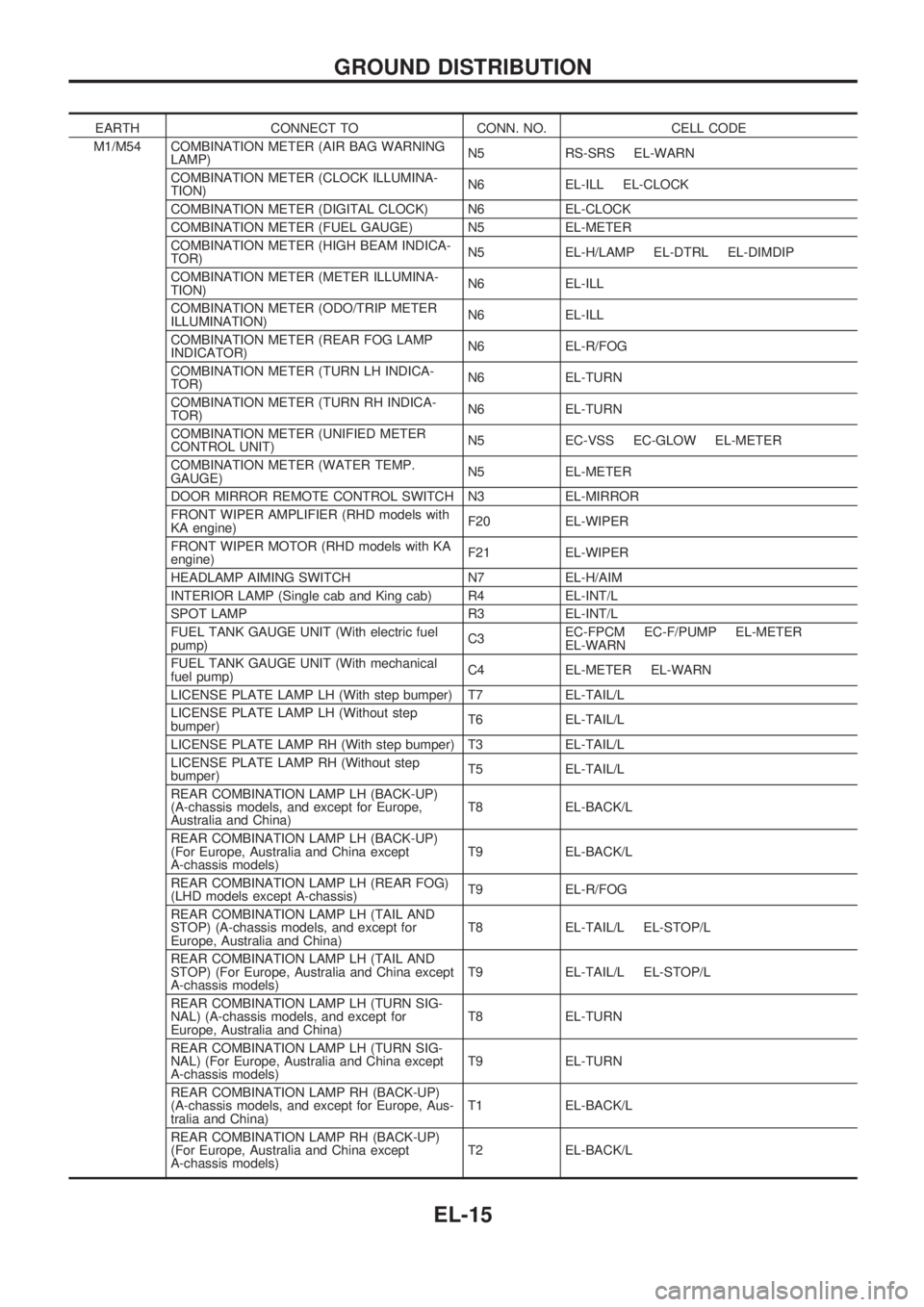
EARTH CONNECT TO CONN. NO. CELL CODE
M1/M54 COMBINATION METER (AIR BAG WARNING
LAMP)N5 RS-SRS EL-WARN
COMBINATION METER (CLOCK ILLUMINA-
TION)N6 EL-ILL EL-CLOCK
COMBINATION METER (DIGITAL CLOCK) N6 EL-CLOCK
COMBINATION METER (FUEL GAUGE) N5 EL-METER
COMBINATION METER (HIGH BEAM INDICA-
TOR)N5 EL-H/LAMP EL-DTRL EL-DIMDIP
COMBINATION METER (METER ILLUMINA-
TION)N6 EL-ILL
COMBINATION METER (ODO/TRIP METER
ILLUMINATION)N6 EL-ILL
COMBINATION METER (REAR FOG LAMP
INDICATOR)N6 EL-R/FOG
COMBINATION METER (TURN LH INDICA-
TOR)N6 EL-TURN
COMBINATION METER (TURN RH INDICA-
TOR)N6 EL-TURN
COMBINATION METER (UNIFIED METER
CONTROL UNIT)N5 EC-VSS EC-GLOW EL-METER
COMBINATION METER (WATER TEMP.
GAUGE)N5 EL-METER
DOOR MIRROR REMOTE CONTROL SWITCH N3 EL-MIRROR
FRONT WIPER AMPLIFIER (RHD models with
KA engine)F20 EL-WIPER
FRONT WIPER MOTOR (RHD models with KA
engine)F21 EL-WIPER
HEADLAMP AIMING SWITCH N7 EL-H/AIM
INTERIOR LAMP (Single cab and King cab) R4 EL-INT/L
SPOT LAMP R3 EL-INT/L
FUEL TANK GAUGE UNIT (With electric fuel
pump)C3EC-FPCM EC-F/PUMP EL-METER
EL-WARN
FUEL TANK GAUGE UNIT (With mechanical
fuel pump)C4 EL-METER EL-WARN
LICENSE PLATE LAMP LH (With step bumper) T7 EL-TAIL/L
LICENSE PLATE LAMP LH (Without step
bumper)T6 EL-TAIL/L
LICENSE PLATE LAMP RH (With step bumper) T3 EL-TAIL/L
LICENSE PLATE LAMP RH (Without step
bumper)T5 EL-TAIL/L
REAR COMBINATION LAMP LH (BACK-UP)
(A-chassis models, and except for Europe,
Australia and China)T8 EL-BACK/L
REAR COMBINATION LAMP LH (BACK-UP)
(For Europe, Australia and China except
A-chassis models)T9 EL-BACK/L
REAR COMBINATION LAMP LH (REAR FOG)
(LHD models except A-chassis)T9 EL-R/FOG
REAR COMBINATION LAMP LH (TAIL AND
STOP) (A-chassis models, and except for
Europe, Australia and China)T8 EL-TAIL/L EL-STOP/L
REAR COMBINATION LAMP LH (TAIL AND
STOP) (For Europe, Australia and China except
A-chassis models)T9 EL-TAIL/L EL-STOP/L
REAR COMBINATION LAMP LH (TURN SIG-
NAL) (A-chassis models, and except for
Europe, Australia and China)T8 EL-TURN
REAR COMBINATION LAMP LH (TURN SIG-
NAL) (For Europe, Australia and China except
A-chassis models)T9 EL-TURN
REAR COMBINATION LAMP RH (BACK-UP)
(A-chassis models, and except for Europe, Aus-
tralia and China)T1 EL-BACK/L
REAR COMBINATION LAMP RH (BACK-UP)
(For Europe, Australia and China except
A-chassis models)T2 EL-BACK/L
GROUND DISTRIBUTION
EL-15
Page 540 of 1659
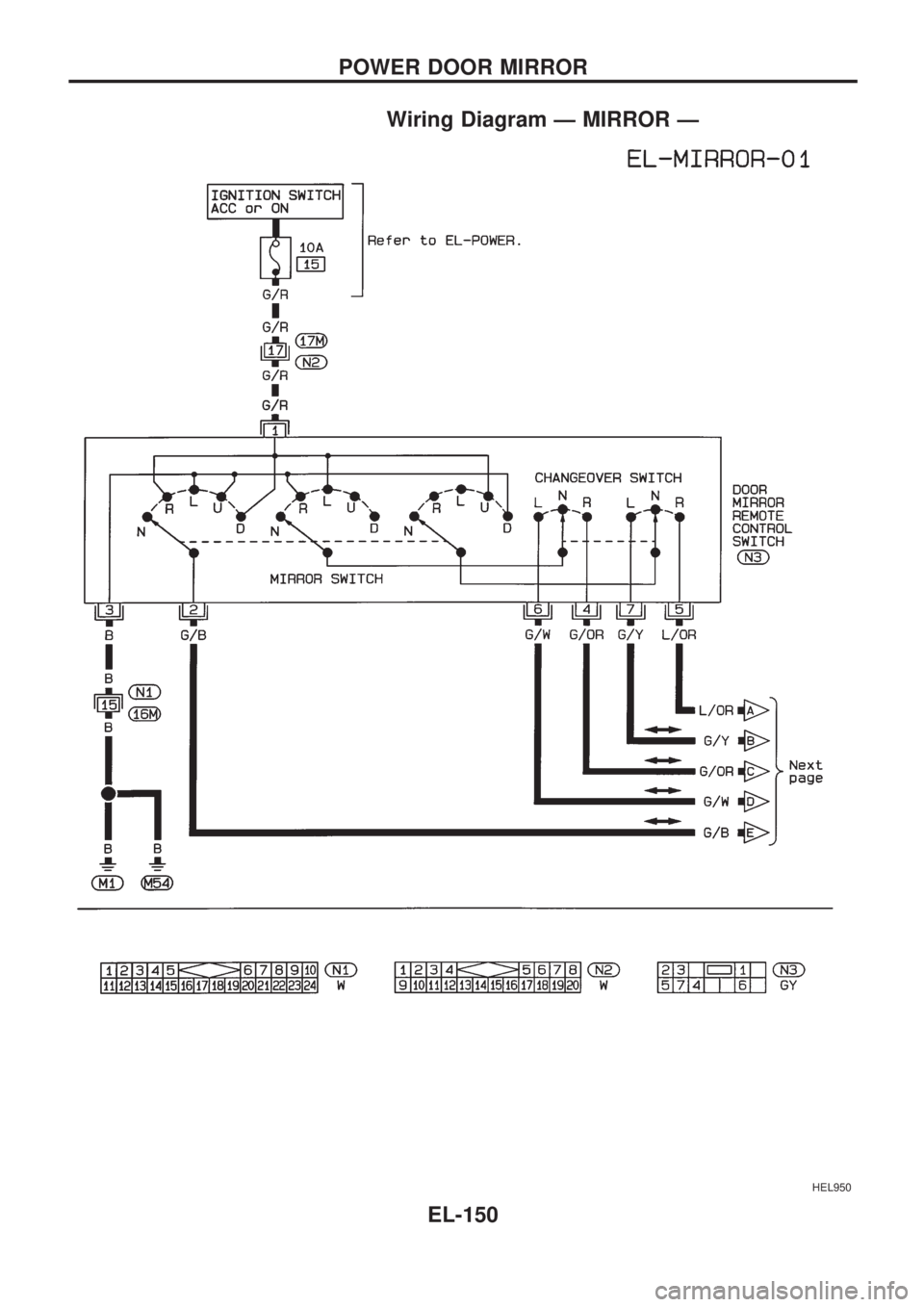
Wiring Diagram Ð MIRROR Ð
HEL950
POWER DOOR MIRROR
EL-150
Page 541 of 1659
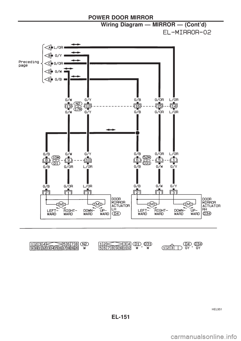
HEL951
POWER DOOR MIRROR
Wiring Diagram Ð MIRROR Ð (Cont'd)
EL-151