1998 NISSAN PICK-UP ad blue
[x] Cancel search: ad bluePage 360 of 1659
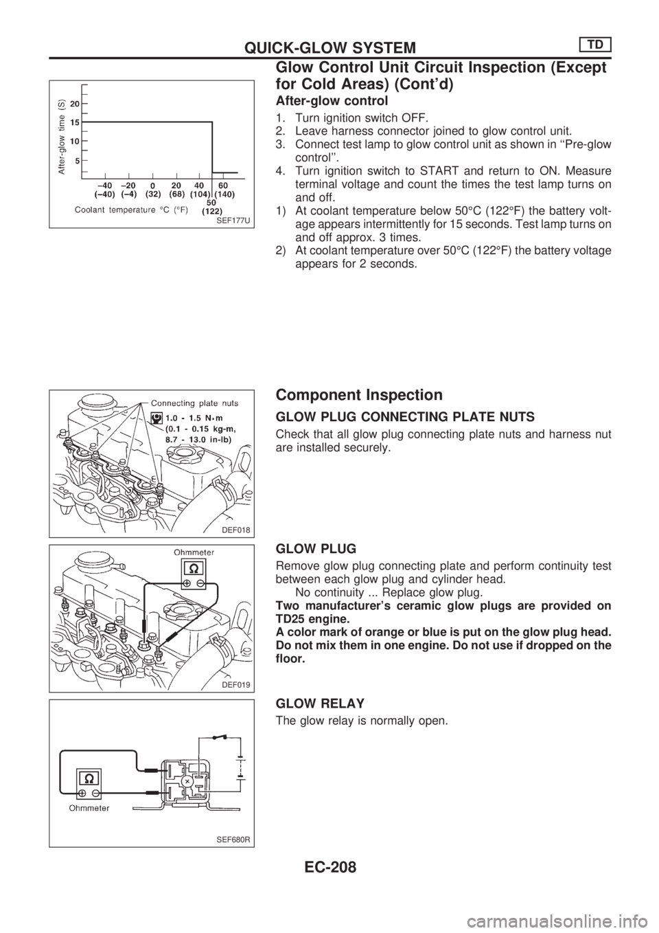
After-glow control
1. Turn ignition switch OFF.
2. Leave harness connector joined to glow control unit.
3. Connect test lamp to glow control unit as shown in ``Pre-glow
control''.
4. Turn ignition switch to START and return to ON. Measure
terminal voltage and count the times the test lamp turns on
and off.
1) At coolant temperature below 50ÉC (122ÉF) the battery volt-
age appears intermittently for 15 seconds. Test lamp turns on
and off approx. 3 times.
2) At coolant temperature over 50ÉC (122ÉF) the battery voltage
appears for 2 seconds.
Component Inspection
GLOW PLUG CONNECTING PLATE NUTS
Check that all glow plug connecting plate nuts and harness nut
are installed securely.
GLOW PLUG
Remove glow plug connecting plate and perform continuity test
between each glow plug and cylinder head.
No continuity ... Replace glow plug.
Two manufacturer's ceramic glow plugs are provided on
TD25 engine.
A color mark of orange or blue is put on the glow plug head.
Do not mix them in one engine. Do not use if dropped on the
floor.
GLOW RELAY
The glow relay is normally open.
SEF177U
DEF018
DEF019
SEF680R
QUICK-GLOW SYSTEMTD
Glow Control Unit Circuit Inspection (Except
for Cold Areas) (Cont'd)
EC-208
Page 689 of 1659
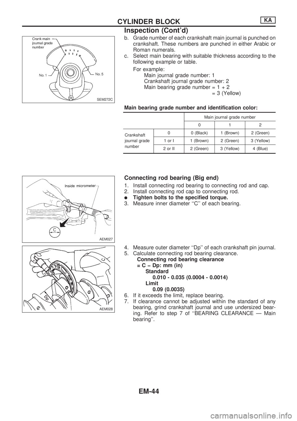
b. Grade number of each crankshaft main journal is punched on
crankshaft. These numbers are punched in either Arabic or
Roman numerals.
c. Select main bearing with suitable thickness according to the
following example or table.
For example:
Main journal grade number: 1
Crankshaft journal grade number: 2
Main bearing grade number=1+2
= 3 (Yellow)
Main bearing grade number and identification color:
Main journal grade number
012
Crankshaft
journal grade
number0 0 (Black) 1 (Brown) 2 (Green)
1 or I 1 (Brown) 2 (Green) 3 (Yellow)
2 or II 2 (Green) 3 (Yellow) 4 (Blue)
Connecting rod bearing (Big end)
1. Install connecting rod bearing to connecting rod and cap.
2. Install connecting rod cap to connecting rod.
lTighten bolts to the specified torque.
3. Measure inner diameter ``C'' of each bearing.
4. Measure outer diameter ``Dp'' of each crankshaft pin journal.
5. Calculate connecting rod bearing clearance.
Connecting rod bearing clearance
= C þ Dp: mm (in)
Standard
0.010 - 0.035 (0.0004 - 0.0014)
Limit
0.09 (0.0035)
6. If it exceeds the limit, replace bearing.
7. If clearance cannot be adjusted within the standard of any
bearing, grind crankshaft journal and use undersized bear-
ing. Refer to step 7 of ``BEARING CLEARANCE Ð Main
bearing''.
SEM272C
AEM027
AEM028
CYLINDER BLOCKKA
Inspection (Cont'd)
EM-44
Page 742 of 1659
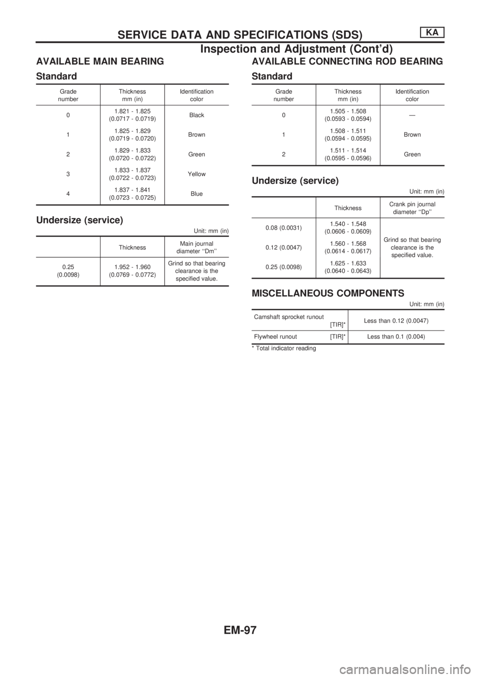
AVAILABLE MAIN BEARING
Standard
Grade
numberThickness
mm (in)Identification
color
01.821 - 1.825
(0.0717 - 0.0719)Black
11.825 - 1.829
(0.0719 - 0.0720)Brown
21.829 - 1.833
(0.0720 - 0.0722)Green
31.833 - 1.837
(0.0722 - 0.0723)Yellow
41.837 - 1.841
(0.0723 - 0.0725)Blue
Undersize (service)
Unit: mm (in)
ThicknessMain journal
diameter ``Dm''
0.25
(0.0098)1.952 - 1.960
(0.0769 - 0.0772)Grind so that bearing
clearance is the
specified value.
AVAILABLE CONNECTING ROD BEARING
Standard
Grade
numberThickness
mm (in)Identification
color
01.505 - 1.508
(0.0593 - 0.0594)Ð
11.508 - 1.511
(0.0594 - 0.0595)Brown
21.511 - 1.514
(0.0595 - 0.0596)Green
Undersize (service)
Unit: mm (in)
ThicknessCrank pin journal
diameter ``Dp''
0.08 (0.0031)1.540 - 1.548
(0.0606 - 0.0609)
Grind so that bearing
clearance is the
specified value. 0.12 (0.0047)1.560 - 1.568
(0.0614 - 0.0617)
0.25 (0.0098)1.625 - 1.633
(0.0640 - 0.0643)
MISCELLANEOUS COMPONENTS
Unit: mm (in)
Camshaft sprocket runout
[TIR]*Less than 0.12 (0.0047)
Flywheel runout [TIR]* Less than 0.1 (0.004)
* Total indicator reading
SERVICE DATA AND SPECIFICATIONS (SDS)KA
Inspection and Adjustment (Cont'd)
EM-97
Page 815 of 1659

Description
Number Item Description
V1Power conditionlThis shows the condition when the system receives battery positive voltage (can
be operated).
V2Fusible link
lThe double line shows that this is a fusible link.
lThe open circle shows current flow in, and the shaded circle shows current flow
out.
V3Fusible link/fuse locationlThis shows the location of the fusible link or fuse in the fusible link or fuse box.
For arrangement, refer to EL section (``POWER SUPPLY ROUTING'').
V4Fuse
lThe single line shows that this is a fuse.
lThe open circle shows current flow in, and the shaded circle shows current flow
out.
V5Current ratinglThis shows the current rating of the fusible link or fuse.
V6Connectors
lThis shows that connectorE3is female and connectorM1is male.
lThe G/R wire is located in the 1A terminal of both connectors.
lTerminal number with an alphabet (1A, 5B, etc.) indicates that the connector is
SMJ connector. Refer to GI-17.
V7Optional splicelThe open circle shows that the splice is optional depending on vehicle application.
V8SplicelThe shaded circle shows that the splice is always on the vehicle.
V9Page crossinglThis arrow shows that the circuit continues to an adjacent page.
lThe A will match with the A on the preceding or next page.
V10Common connectorlThe dotted lines between terminals show that these terminals are part of the same
connector.
V11Option abbreviationlThis shows that the circuit is optional depending on vehicle application.
V12RelaylThis shows an internal representation of the relay. For details, refer to EL section
(``STANDARDIZED RELAY'').
V13ConnectorslThis shows that the connector is connected to the body or a terminal with bolt or
nut.
V14Wire color
lThis shows a code for the color of the wire.
B = Black BR = Brown
W = White OR = Orange
R = Red P = Pink
G = Green PU = Purple
L = Blue GY = Gray
Y = Yellow SB = Sky Blue
LG = Light Green CH = Dark Brown
DG = Dark Green
When the wire color is striped, the base color is given first, followed by the stripe
color as shown below:
Example: L/W = Blue with White Stripe
V15Option descriptionlThis shows a description of the option abbreviation used on the page.
V16Switch
lThis shows that continuity exists between terminals 1 and 2 when the switch is in
the A position. Continuity exists between terminals 1 and 3 when the switch is in
the B position.
V17Assembly partslConnector terminal in component shows that it is a harness incorporated assem-
bly.
V18Cell codelThis identifies each page of the wiring diagram by section, system and wiring dia-
gram page number.
HOW TO READ WIRING DIAGRAMS
GI-11
Page 879 of 1659
HFC-134a (R-134a) Service Tools and
Equipment
Never mix HFC-134a refrigerant and/or its specified lubricant with CFC-12 (R-12) refrigerant and/or its lubri-
cation oil.
Separate and non-interchangeable service equipment must be used for each type of refrigerant/lubricant.
Refrigerant container fittings, service hose fittings and service equipment fittings (equipment which handles
refrigerant and/or lubricant) are different between CFC-12 (R-12) and HFC-134a (R-134a). This is to avoid
mixed use of the refrigerants/lubricant.
Adapters that convert one size fitting to another must never be used: refrigerant/lubricant contamination will
occur and compressor failure will result.
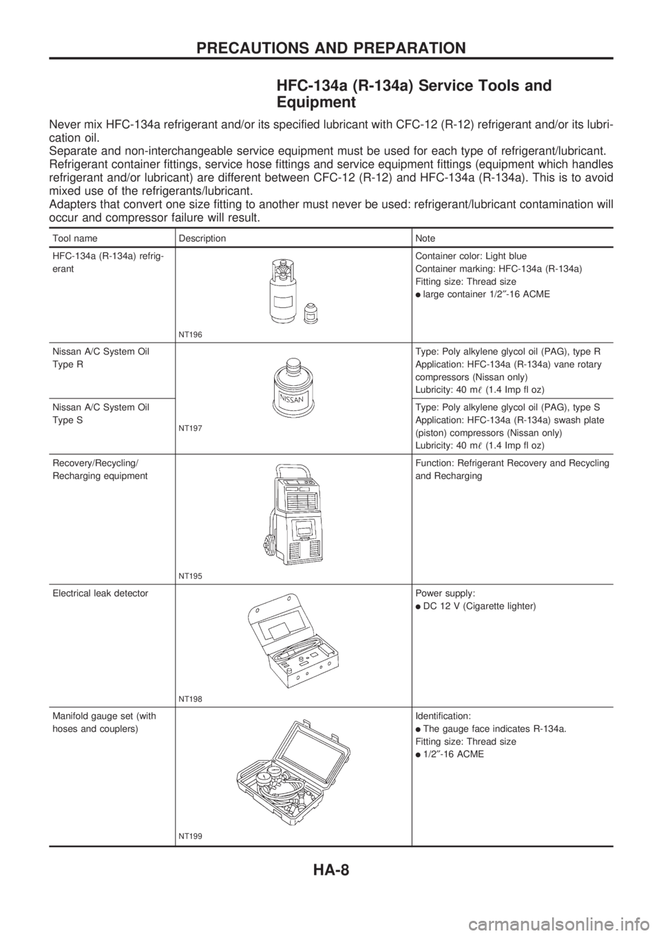
Tool name Description Note
HFC-134a (R-134a) refrig-
erant
NT196
Container color: Light blue
Container marking: HFC-134a (R-134a)
Fitting size: Thread size
llarge container 1/2²-16 ACME
Nissan A/C System Oil
Type R
NT197
Type: Poly alkylene glycol oil (PAG), type R
Application: HFC-134a (R-134a) vane rotary
compressors (Nissan only)
Lubricity: 40 m!(1.4 Imp fl oz)
Nissan A/C System Oil
Type SType: Poly alkylene glycol oil (PAG), type S
Application: HFC-134a (R-134a) swash plate
(piston) compressors (Nissan only)
Lubricity: 40 m!(1.4 Imp fl oz)
Recovery/Recycling/
Recharging equipment
NT195
Function: Refrigerant Recovery and Recycling
and Recharging
Electrical leak detector
NT198
Power supply:
lDC 12 V (Cigarette lighter)
Manifold gauge set (with
hoses and couplers)
NT199
Identification:
lThe gauge face indicates R-134a.
Fitting size: Thread size
l1/2²-16 ACME
PRECAUTIONS AND PREPARATION
HA-8
Page 880 of 1659
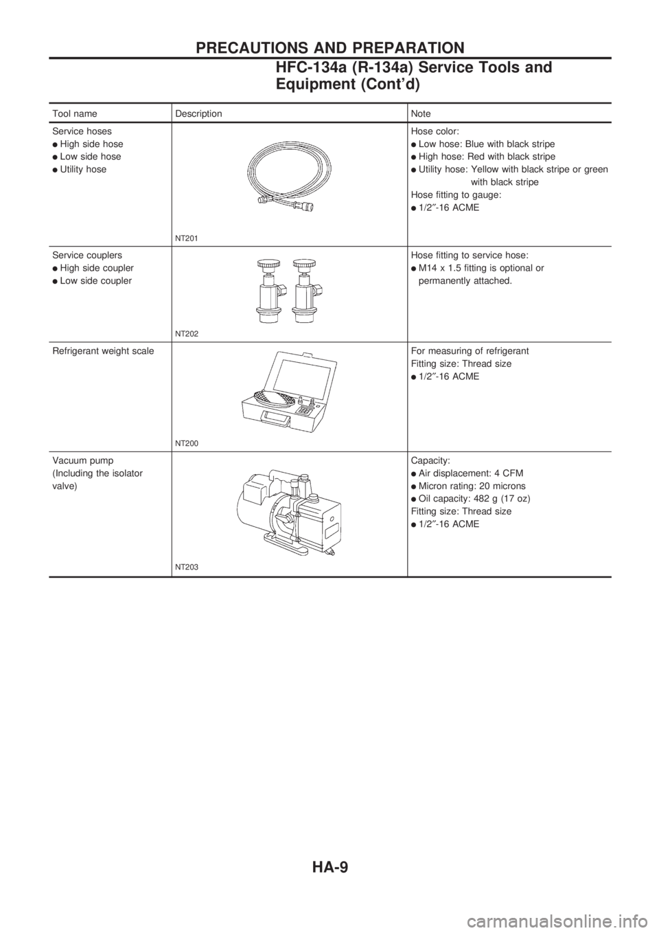
Tool name Description Note
Service hoses
lHigh side hose
lLow side hose
lUtility hose
NT201
Hose color:
lLow hose: Blue with black stripe
lHigh hose: Red with black stripe
lUtility hose: Yellow with black stripe or green
with black stripe
Hose fitting to gauge:
l1/2²-16 ACME
Service couplers
lHigh side coupler
lLow side coupler
NT202
Hose fitting to service hose:
lM14 x 1.5 fitting is optional or
permanently attached.
Refrigerant weight scale
NT200
For measuring of refrigerant
Fitting size: Thread size
l1/2²-16 ACME
Vacuum pump
(Including the isolator
valve)
NT203
Capacity:
lAir displacement: 4 CFM
lMicron rating: 20 microns
lOil capacity: 482 g (17 oz)
Fitting size: Thread size
l1/2²-16 ACME
PRECAUTIONS AND PREPARATION
HFC-134a (R-134a) Service Tools and
Equipment (Cont'd)
HA-9
Page 1157 of 1659
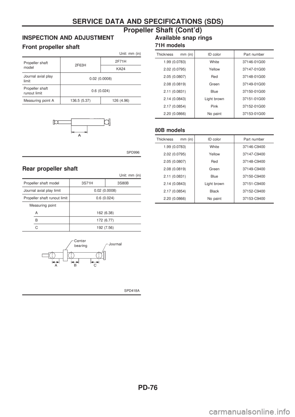
INSPECTION AND ADJUSTMENT
Front propeller shaft
Unit: mm (in)
Propeller shaft
model2F63H2F71H
KA24
Journal axial play
limit0.02 (0.0008)
Propeller shaft
runout limit0.6 (0.024)
Measuring point A 136.5 (5.37) 126 (4.96)
SPD996
Rear propeller shaft
Unit: mm (in)
Propeller shaft model 3S71H 3S80B
Journal axial play limit 0.02 (0.0008)
Propeller shaft runout limit 0.6 (0.024)
Measuring point
A 162 (6.38)
B 172 (6.77)
C 192 (7.56)
SPD418A
Available snap rings
71H models
Thickness mm (in) ID color Part number
1.99 (0.0783) White 37146-01G00
2.02 (0.0795) Yellow 37147-01G00
2.05 (0.0807) Red 37148-01G00
2.08 (0.0819) Green 37149-01G00
2.11 (0.0831) Blue 37150-01G00
2.14 (0.0843) Light brown 37151-01G00
2.17 (0.0854) Pink 37152-01G00
2.20 (0.0866) No paint 37153-01G00
80B models
Thickness mm (in) ID color Part number
1.99 (0.0783) White 37146-C9400
2.02 (0.0795) Yellow 37147-C9400
2.05 (0.0807) Red 37148-C9400
2.08 (0.0819) Green 37149-C9400
2.11 (0.0831) Blue 37150-C9400
2.14 (0.0843) Light brown 37151-C9400
2.17 (0.0854) Black 37152-C9400
2.20 (0.0866) No paint 37153-C9400
SERVICE DATA AND SPECIFICATIONS (SDS)
Propeller Shaft (Cont'd)
PD-76
Page 1597 of 1659
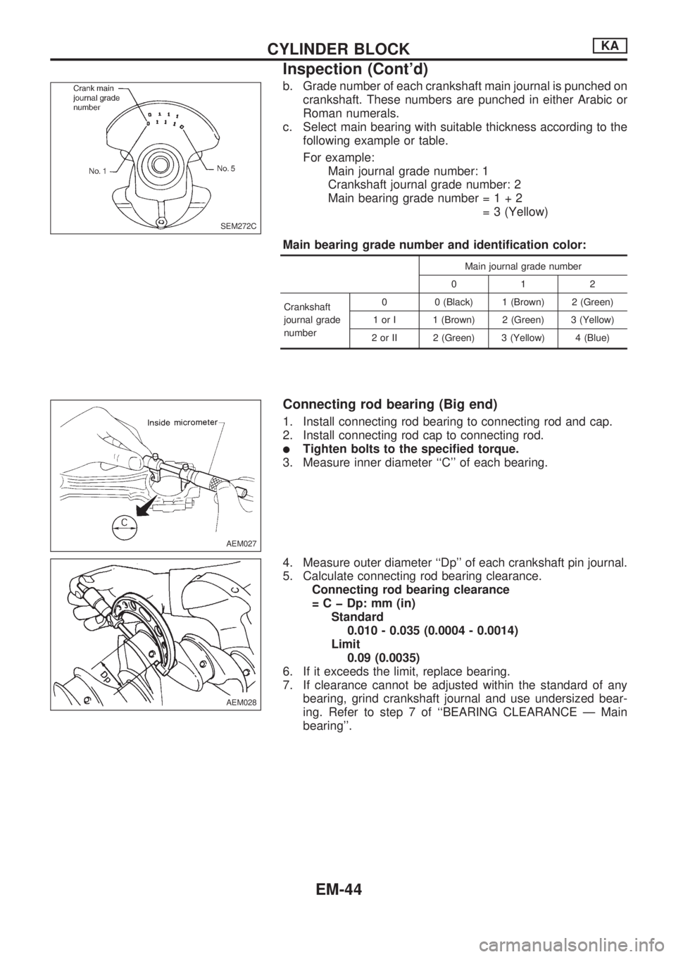
b. Grade number of each crankshaft main journal is punched on
crankshaft. These numbers are punched in either Arabic or
Roman numerals.
c. Select main bearing with suitable thickness according to the
following example or table.
For example:
Main journal grade number: 1
Crankshaft journal grade number: 2
Main bearing grade number=1+2
= 3 (Yellow)
Main bearing grade number and identification color:
Main journal grade number
012
Crankshaft
journal grade
number0 0 (Black) 1 (Brown) 2 (Green)
1 or I 1 (Brown) 2 (Green) 3 (Yellow)
2 or II 2 (Green) 3 (Yellow) 4 (Blue)
Connecting rod bearing (Big end)
1. Install connecting rod bearing to connecting rod and cap.
2. Install connecting rod cap to connecting rod.
lTighten bolts to the specified torque.
3. Measure inner diameter ``C'' of each bearing.
4. Measure outer diameter ``Dp'' of each crankshaft pin journal.
5. Calculate connecting rod bearing clearance.
Connecting rod bearing clearance
= C þ Dp: mm (in)
Standard
0.010 - 0.035 (0.0004 - 0.0014)
Limit
0.09 (0.0035)
6. If it exceeds the limit, replace bearing.
7. If clearance cannot be adjusted within the standard of any
bearing, grind crankshaft journal and use undersized bear-
ing. Refer to step 7 of ``BEARING CLEARANCE Ð Main
bearing''.
SEM272C
AEM027
AEM028
CYLINDER BLOCKKA
Inspection (Cont'd)
EM-44