1998 NISSAN PICK-UP seat adjustment
[x] Cancel search: seat adjustmentPage 389 of 1659
HEADLAMP - Headlamp Aiming Control -........... 63
System Description .............................................. 63
Wiring Diagram - H/AIM - .................................... 64
PARKING, LICENSE AND TAIL LAMPS............... 66
Wiring Diagram - TAIL/L -/Except for LHD
Models for Europe ............................................... 66
Wiring Diagram - TAIL/L -/LHD Models for
Europe.................................................................. 68
STOP LAMP............................................................ 70
Wiring Diagram - STOP/L - ................................. 70
BACK-UP LAMP...................................................... 71
Wiring Diagram - BACK/L - ................................. 71
REAR FOG LAMP................................................... 72
Wiring Diagram - R/FOG -/LHD Models .............. 72
Wiring Diagram - R/FOG -/RHD Models ............. 73
TURN SIGNAL AND HAZARD WARNING
LAMPS..................................................................... 74
Schematic ............................................................ 74
Wiring Diagram - TURN -/Except 4WD Models
for Europe ............................................................ 75
Wiring Diagram - TURN -/4WD Models for
Europe.................................................................. 77
Trouble Diagnoses ............................................... 80
Combination Flasher Unit Check ......................... 80
ILLUMINATION........................................................ 81
Wiring Diagram - ILL -/LHD Models .................... 81
Wiring Diagram - ILL -/RHD Models.................... 83
INTERIOR AND SPOT LAMPS............................... 85
Wiring Diagram - INT/L - ..................................... 85
Combination Meter............................................... 87
Schematic ............................................................ 89
Wiring Diagram - METER -/LHD Models............. 90
Wiring Diagram - METER -/RHD Models ............ 93
Unified Control Meter System Description .......... 96
Meter/gauge Operation and Odo/Trip Meter
Segment Check in Diagnosis Mode .................... 96
Flexible Print Circuit (FPC) .................................. 97
Trouble Diagnoses ............................................... 98
Electrical Components Inspection ..................... 103
WARNING LAMPS................................................ 105
Schematic .......................................................... 105
Wiring Diagram - WARN -/LHD Models ............ 106
Wiring Diagram - WARN -/RHD Models............ 111
Electrical Components Inspection ..................... 116
WARNING BUZZER.............................................. 117
Wiring diagram - BUZZER -/LHD Models for
Europe................................................................ 117
Wiring diagram - BUZZER -/RHD Models for
Europe................................................................ 118
Electrical Components Inspection ..................... 119
FRONT WIPER AND WASHER............................ 120
System Description ............................................ 120
Wiring Diagram - WIPER -/LHD Models with
Intermittent ......................................................... 122Wiring Diagram - WIPER -/RHD Models with
Intermittent ......................................................... 124
Trouble Diagnoses ............................................. 126
Wiper Installation and Adjustment ..................... 127
Washer Nozzle Adjustment ............................... 128
Washer Tube Layout ......................................... 128
Wiper Linkage .................................................... 129
HEADLAMP WASHER.......................................... 130
Wiring Diagram - HLC - ..................................... 130
Trouble Diagnoses ............................................. 131
Washer Tube Layout ......................................... 131
Check Valve ....................................................... 131
HORN..................................................................... 132
Wiring Diagram - HORN -.................................. 132
CIGARETTE LIGHTER.......................................... 133
Wiring Diagram - CIGAR - ................................. 133
CLOCK................................................................... 134
Wiring Diagram - CLOCK - ................................ 134
REAR WINDOW DEFOGGER............................... 135
Wiring Diagram - DEF - ..................................... 135
Electrical Components Inspection ..................... 136
Filament Check .................................................. 136
Filament Repair.................................................. 137
AUDIO.................................................................... 138
Wiring Diagram - AUDIO -/LHD Models Type-
2 ......................................................................... 138
Wiring Diagram - AUDIO -/LHD Models Type-
3 ......................................................................... 139
Wiring Diagram - AUDIO -/RHD Models ........... 141
Trouble Diagnoses ............................................. 142
CATS (Code) System/For Europe RHD ............ 143
NATS Audio Link/For Europe LHD (KA24E) ..... 144
AUDIO ANTENNA................................................. 146
Manual Antenna ................................................. 146
Power Antenna/Wiring Diagram - P/ANT - ........ 147
Power Antenna .................................................. 148
POWER DOOR MIRROR...................................... 150
Wiring Diagram - MIRROR -.............................. 150
HEATED SEAT...................................................... 152
Wiring Diagram - H/SEAT - ............................... 152
POWER WINDOW................................................. 154
System Description ............................................ 154
Schematic .......................................................... 156
Wiring Diagram - WINDOW -/LHD Models ....... 157
Wiring Diagram - WINDOW -/RHD Models ....... 161
Trouble Diagnoses ............................................. 165
POWER DOOR LOCK........................................... 166
System Description ............................................ 166
Wiring Diagram - D/LOCK - ............................... 167
Trouble Diagnosis .............................................. 169
MULTI-REMOTE CONTROL SYSTEM/FOR
EUROPE................................................................ 173
System Description ............................................ 173
Schematic .......................................................... 174
Page 737 of 1659
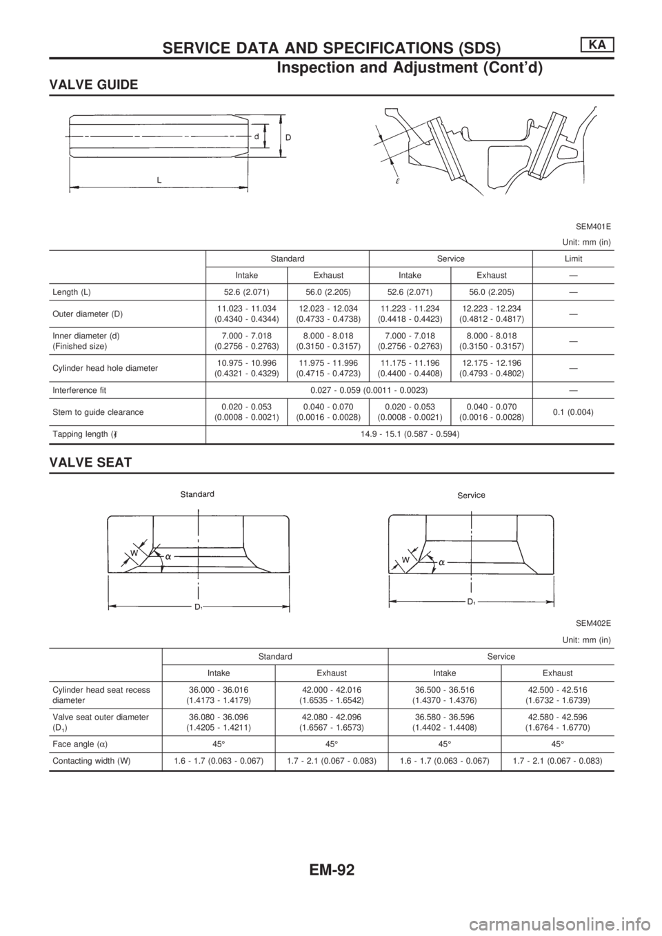
VALVE GUIDE
SEM401E
Unit: mm (in)
Standard Service Limit
Intake Exhaust Intake Exhaust Ð
Length (L) 52.6 (2.071) 56.0 (2.205) 52.6 (2.071) 56.0 (2.205) Ð
Outer diameter (D)11.023 - 11.034
(0.4340 - 0.4344)12.023 - 12.034
(0.4733 - 0.4738)11.223 - 11.234
(0.4418 - 0.4423)12.223 - 12.234
(0.4812 - 0.4817)Ð
Inner diameter (d)
(Finished size)7.000 - 7.018
(0.2756 - 0.2763)8.000 - 8.018
(0.3150 - 0.3157)7.000 - 7.018
(0.2756 - 0.2763)8.000 - 8.018
(0.3150 - 0.3157)Ð
Cylinder head hole diameter10.975 - 10.996
(0.4321 - 0.4329)11.975 - 11.996
(0.4715 - 0.4723)11.175 - 11.196
(0.4400 - 0.4408)12.175 - 12.196
(0.4793 - 0.4802)Ð
Interference fit 0.027 - 0.059 (0.0011 - 0.0023) Ð
Stem to guide clearance0.020 - 0.053
(0.0008 - 0.0021)0.040 - 0.070
(0.0016 - 0.0028)0.020 - 0.053
(0.0008 - 0.0021)0.040 - 0.070
(0.0016 - 0.0028)0.1 (0.004)
Tapping length (,) 14.9 - 15.1 (0.587 - 0.594)
VALVE SEAT
SEM402E
Unit: mm (in)
Standard Service
Intake Exhaust Intake Exhaust
Cylinder head seat recess
diameter36.000 - 36.016
(1.4173 - 1.4179)42.000 - 42.016
(1.6535 - 1.6542)36.500 - 36.516
(1.4370 - 1.4376)42.500 - 42.516
(1.6732 - 1.6739)
Valve seat outer diameter
(D
1)36.080 - 36.096
(1.4205 - 1.4211)42.080 - 42.096
(1.6567 - 1.6573)36.580 - 36.596
(1.4402 - 1.4408)42.580 - 42.596
(1.6764 - 1.6770)
Face angle (a) 45É 45É 45É 45É
Contacting width (W) 1.6 - 1.7 (0.063 - 0.067) 1.7 - 2.1 (0.067 - 0.083) 1.6 - 1.7 (0.063 - 0.067) 1.7 - 2.1 (0.067 - 0.083)
SERVICE DATA AND SPECIFICATIONS (SDS)KA
Inspection and Adjustment (Cont'd)
EM-92
Page 743 of 1659
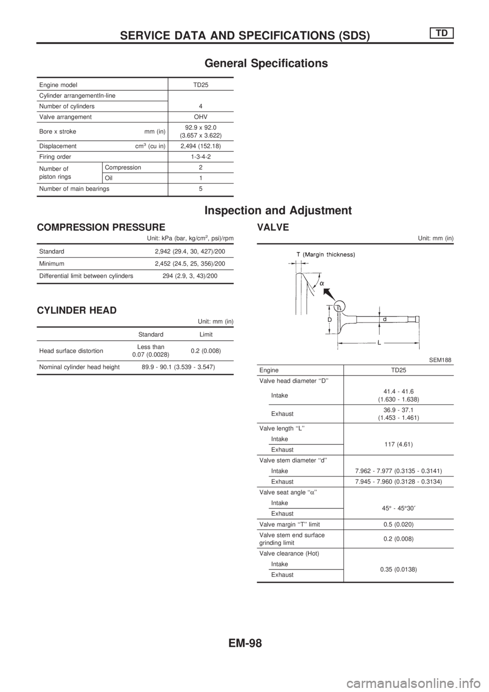
General Specifications
Engine model TD25
Cylinder arrangementIn-line
Number of cylinders 4
Valve arrangement OHV
Bore x stroke mm (in)92.9 x 92.0
(3.657 x 3.622)
Displacement cm
3(cu in) 2,494 (152.18)
Firing order 1-3-4-2
Number of
piston ringsCompression 2
Oil 1
Number of main bearings 5
Inspection and Adjustment
COMPRESSION PRESSURE
Unit: kPa (bar, kg/cm2, psi)/rpm
Standard 2,942 (29.4, 30, 427)/200
Minimum 2,452 (24.5, 25, 356)/200
Differential limit between cylinders 294 (2.9, 3, 43)/200
CYLINDER HEAD
Unit: mm (in)
Standard Limit
Head surface distortionLess than
0.07 (0.0028)0.2 (0.008)
Nominal cylinder head height 89.9 - 90.1 (3.539 - 3.547)
VALVE
Unit: mm (in)
SEM188
Engine TD25
Valve head diameter ``D''
Intake41.4 - 41.6
(1.630 - 1.638)
Exhaust36.9 - 37.1
(1.453 - 1.461)
Valve length ``L''
Intake
117 (4.61)
Exhaust
Valve stem diameter ``d''
Intake 7.962 - 7.977 (0.3135 - 0.3141)
Exhaust 7.945 - 7.960 (0.3128 - 0.3134)
Valve seat angle ``a''
Intake
45É - 45É30¢
Exhaust
Valve margin ``T'' limit 0.5 (0.020)
Valve stem end surface
grinding limit0.2 (0.008)
Valve clearance (Hot)
Intake
0.35 (0.0138)
Exhaust
SERVICE DATA AND SPECIFICATIONS (SDS)TD
EM-98
Page 745 of 1659
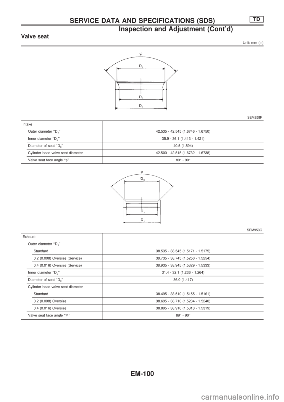
Valve seat
Unit: mm (in)
SEM258F
Intake
Outer diameter ``D
1'' 42.535 - 42.545 (1.6746 - 1.6750)
Inner diameter ``D
2'' 35.9 - 36.1 (1.413 - 1.421)
Diameter of seat ``D
3'' 40.5 (1.594)
Cylinder head valve seat diameter 42.500 - 42.515 (1.6732 - 1.6738)
Valve seat face angle ``f'' 89É - 90É
SEM953C
Exhaust
Outer diameter ``D
1''
Standard 38.535 - 38.545 (1.5171 - 1.5175)
0.2 (0.008) Oversize (Service) 38.735 - 38.745 (1.5250 - 1.5254)
0.4 (0.016) Oversize (Service) 38.935 - 38.945 (1.5329 - 1.5333)
Inner diameter ``D
2'' 31.4 - 32.1 (1.236 - 1.264)
Diameter of seat ``D
3'' 36.0 (1.417)
Cylinder head valve seat diameter
Standard 38.495 - 38.510 (1.5155 - 1.5161)
0.2 (0.008) Oversize 38.695 - 38.710 (1.5234 - 1.5240)
0.4 (0.016) Oversize 38.895 - 38.910 (1.5313 - 1.5319)
Valve seat face angle ``J'' 89É - 90É
SERVICE DATA AND SPECIFICATIONS (SDS)TD
Inspection and Adjustment (Cont'd)
EM-100
Page 770 of 1659
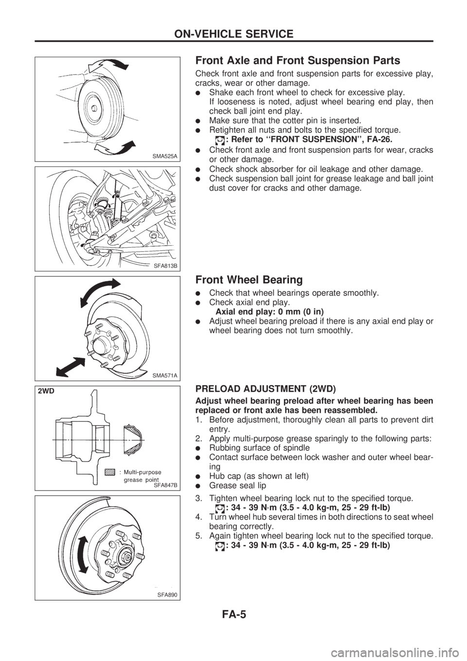
Front Axle and Front Suspension Parts
Check front axle and front suspension parts for excessive play,
cracks, wear or other damage.
lShake each front wheel to check for excessive play.
If looseness is noted, adjust wheel bearing end play, then
check ball joint end play.
lMake sure that the cotter pin is inserted.
lRetighten all nuts and bolts to the specified torque.
: Refer to ``FRONT SUSPENSION'', FA-26.
lCheck front axle and front suspension parts for wear, cracks
or other damage.
lCheck shock absorber for oil leakage and other damage.
lCheck suspension ball joint for grease leakage and ball joint
dust cover for cracks and other damage.
Front Wheel Bearing
lCheck that wheel bearings operate smoothly.
lCheck axial end play.
Axial end play: 0 mm (0 in)
lAdjust wheel bearing preload if there is any axial end play or
wheel bearing does not turn smoothly.
PRELOAD ADJUSTMENT (2WD)
Adjust wheel bearing preload after wheel bearing has been
replaced or front axle has been reassembled.
1. Before adjustment, thoroughly clean all parts to prevent dirt
entry.
2. Apply multi-purpose grease sparingly to the following parts:
lRubbing surface of spindle
lContact surface between lock washer and outer wheel bear-
ing
lHub cap (as shown at left)
lGrease seal lip
3. Tighten wheel bearing lock nut to the specified torque.
: 34 - 39 N´m (3.5 - 4.0 kg-m, 25 - 29 ft-lb)
4. Turn wheel hub several times in both directions to seat wheel
bearing correctly.
5. Again tighten wheel bearing lock nut to the specified torque.
: 34 - 39 N´m (3.5 - 4.0 kg-m, 25 - 29 ft-lb)
SMA525A
SFA813B
SMA571A
SFA847B
SFA890
ON-VEHICLE SERVICE
FA-5
Page 866 of 1659

EVAP vapor lines inspection ....................... MA-22
Electrical diagnoses ...................................... GI-21
Engine compartment .................................... BT-44
Engine control module (ECM) ....................... EC-5
Engine coolant temperature sensor
(ECTS) (KA24 engine) ............................. EC-95
Engine coolant temperature sensor
(ECTS) (TD25 engine) ........................... EC-209
Engine oil filter replacement
(KA24 engine).......................................... MA-20
Engine oil filter replacement
(TD25 engine).......................................... MA-24
Engine oil precautions .................................... GI-4
Engine oil replacement
(KA24 engine).......................................... MA-19
Engine oil replacement
(TD25 engine).......................................... MA-24
Engine outer component parts
(KA24 engine)............................................ EM-9
Engine outer component parts
(TD25 engine).......................................... EM-49
Engine removal (KA24 engine) ................... EM-36
Engine removal (TD25 engine) ................... EM-69
Engine room - See Engine
compartment............................................. BT-44
Engine speed sensor ................................. EC-219
Evaporative emission (EVAP) system ......... EC-19
Exhaust system inspection.......................... MA-32
Exhaust system .............................................. FE-5
Exterior ......................................................... BT-24
F
F/PUMP - Wiring diagram...........................EC-153
FCUT - Wiring diagram ............................. EC-225
FICD - Wiring diagram (KA24 engine) ...... EC-168
FICD - Wiring diagram (TD25 engine) ...... EC-230
Fan switch.................................................... HA-43
Fast idle cam (FIC) inspection and
adjustment................................................ EC-24
Final drive disassembly (C200) ................... PD-34
Final drive disassembly (H233B)................. PD-56
Final drive pre-inspection (C200) ................ PD-34
Final drive pre-inspection (H233B) .............. PD-56
Final drive removal and installation ............. PD-15
Floor trim ...................................................... BT-15
Flow charts.................................................... GI-31
Fluids ........................................................... MA-12
Flywheel (clutch) .......................................... CL-12
Flywheel runout (KA24 engine)................... EM-45
Flywheel runout (TD25 engine)................... EM-80
Fog lamp, rear .............................................. EL-72
Fork rod (M/T) (FS5R30A) .......................... MT-38
Fork rod (M/T) (FS5W71C) ......................... MT-17
Front axle ..................................................... FA-12
Front bumper.................................................. BT-5
Front case (Transfer) ..................................... TF-8
Front combination lamp removal and
installation................................................... BT-5Front disc brake ........................................... BR-21
Front door..................................................... BT-10
Front drive shaft (Transfer) ............................ TF-9
Front final drive disassembly (4WD) ........... PD-17
Front final drive pre-inspection (4WD) ........ PD-17
Front final drive removal and installa-
tion (4WD) ................................................ PD-14
Front seat belt................................................ RS-3
Front seat ..................................................... BT-30
Front suspension.......................................... FA-26
Front washer .............................................. EL-120
Front wiper ................................................. EL-120
Fuel check valve .......................................... EC-20
Fuel cut control (at no load & high
engine speed) (KA24 engine) .................. EC-18
Fuel cut control (at no load & high
engine speed) ........................................ EC-225
Fuel filter replacement (KA24 engine) ........ MA-18
Fuel filter replacement (TD25 engine) ........ MA-27
Fuel injector ............................................... EC-144
Fuel line inspection (KA24 engine) ............. MA-18
Fuel line inspection (TD25 engine) ............. MA-28
Fuel precautions ............................................. GI-5
Fuel pressure check .................................... EC-22
Fuel pressure release .................................. EC-22
Fuel pump .................................................. EC-151
Fuel pump relay ......................................... EC-156
Fuel system .................................................... FE-3
Fuel tank vacuum relief valve...................... EC-20
Fuse block.................................................. Foldout
Fuse.............................................................. EL-13
Fusible link ................................................... EL-13G
GLOW - Wiring diagram .............................EC-197
Garage jack and safety stand....................... GI-49
Gear components (M/T) (FS5R30A) ........... MT-36
Gear components (M/T) (FS5W71C) .......... MT-15
Glass ............................................................ BT-10
Glow plug ................................................... EC-208
Glow relay .................................................. EC-208
Grease ......................................................... MA-12
Ground clearance ......................................... GI-44
Ground distribution ....................................... EL-14
H
H/AIM - Wiring diagram .................................EL-64
H/LAMP - Wiring diagram ............................ EL-44
H02S - Wiring diagram .............................. EC-124
HFC134a (R134a) system precaution ........... HA-2
HFC134a (R134a) system service
procedure ................................................. HA-48
HFC134a (R134a) system service
tools............................................................ HA-8
HFC134a system service equipment
precaution ................................................ HA-10
ALPHABETICAL INDEX
IDX-4
Page 867 of 1659

HLC - Wiring diagram ................................ EL-130
HORN - Wiring diagram ............................. EL-132
H/SEAT - Wiring diagram........................... EL-152
Harness connector ......................................... EL-2
Harness connector inspection ...................... GI-18
Harness layout ........................................... EL-220
Hazard warning lamp ................................... EL-74
Headlamp ..................................................... EL-44
Headlamp aiming control ............................. EL-63
Headlamp leveler - See Headlamp
aiming control ........................................... EL-63
Headlamp washer ...................................... EL-130
Heated oxygen sensor (HO2S) ................. EC-123
Heated oxygen sensor heater ................... EC-127
Heated oxygen sensor inspection ............... MA-22
Heated seat .................................................. BT-32
Heated seat ................................................ EL-152
Height (Dimensions) ..................................... GI-44
Hood ............................................................... BT-5
Horn ............................................................ EL-132
How to erase DTC for ECCS OBD
system ...................................................... EC-36
I
IACV-AAC valve .................................EC-131, 135
IACV-FICD solenoid valve
(KA24 engine) ........................................ EC-168
IACV-FICD solenoid valve
(TD25 engine) ........................................ EC-231
IATS - Wiring diagram ............................... EC-110
IGN/SG - Wiring diagram .......................... EC-101
ILL - Wiring diagram..................................... EL-81
INJECT - Wiring diagram .......................... EC-144
INT/L - Wiring diagram ................................. EL-85
Identification plate ......................................... GI-42
Idle mixture ratio .......................................... EC-25
Idle speed .................................................... EC-25
Idle speed inspection .................................. MA-30
Ignition coil ................................................. EC-105
Ignition timing............................................... EC-25
Ignition wire inspection ................................ MA-21
Illumination ................................................... EL-81
Injection nozzle inspection .......................... MA-29
Injection nozzle .......................................... EC-186
Injector ............................................... EC-144, 148
Injector removal and installation .................. EC-23
Instrument panel .......................................... BT-12
Intake air temperature sensor ................... EC-109
Intake door control linkage
adjustment................................................ HA-47
Intake manifold .............................................. EM-9
Interior lamp ................................................. EL-85
Interior .......................................................... BT-15
J
Jacking points ................................................GI-47Journal bearing assembly
(propeller shaft) ........................................ PD-11
Journal bearing disassembly
(propeller shaft) ........................................ PD-10
Jump seat..................................................... BT-34
K
Keyless entry system - See Multi-remote
control system .............................................EL-173
Knuckle spindle ............................................ FA-18
L
LSV (Load sensing valve)...............................BR-7
Leaf spring (rear) ......................................... RA-13
Length (Dimensions) ..................................... GI-44
License lamp ................................................ EL-66
Lifting points .................................................. GI-47
Limited slip diff. adjustment (C200) ............. PD-41
Limited slip diff. adjustment (H233B) .......... PD-63
Limited slip diff. assembly (C200) ............... PD-43
Limited slip diff. assembly (H233B) ............. PD-64
Limited slip diff. disassembly (C200)........... PD-39
Limited slip diff. disassembly (H233B) ........ PD-61
Limited slip diff. inspection (C200) .............. PD-40
Limited slip diff. inspection (H233B) ............ PD-62
Liquid gasket application ............................... EM-1
Location of electrical units.......................... EL-217
Lock, door .................................................... BT-10
Lubricant (R134a) A/C ................................. HA-50
Lubricants .................................................... MA-12
Lubrication circuit (engine)
(KA24 engine) ............................................ LC-3
Lubrication circuit (engine)
(TD25 engine) .......................................... LC-12
Lubrication-locks, hinges and hood
latches ..................................................... MA-39
M
M/T major overhaul (FS5R30A) ...................MT-35
M/T major overhaul (FS5W71C) ................. MT-14
M/T removal and installation ....................... MT-11
MAFS - Wiring diagram ............................... EC-91
MAIN - Wiring diagram ................................ EC-76
METER - Wiring diagram ............................. EL-90
MIL & Data link connectors ....................... EC-173
MIRROR - Wiring diagram ......................... EL-150
MULTI - Wiring diagram ............................. EL-175
Main drive gear (M/T) (FS5R30A)............... MT-36
Main drive gear (M/T) (FS5W71C).............. MT-15
Main gear (Transfer) ...................................... TF-9
Mainshaft (M/T) (FS5R30A) ........................ MT-36
Mainshaft (M/T) (FS5W71C) ....................... MT-15
Mainshaft (Transfer) ....................................... TF-9
Maintenance (engine) (KA24 engine) ......... MA-15
ALPHABETICAL INDEX
IDX-5
Page 869 of 1659
Radiator (KA24 engine) ................................. LC-9
Radiator (TD25 engine) ............................... LC-24
Rear axle ....................................................... RA-5
Rear body..................................................... BT-40
Rear case (Transfer) ...................................... TF-8
Rear combination lamp removal and
installation................................................. BT-24
Rear cover gasket replacement diff. ........... PD-13
Rear door ..................................................... BT-11
Rear drum brake.......................................... BR-26
Rear fog lamp............................................... EL-72
Rear seat belt ................................................ RS-4
Rear seat...................................................... BT-33
Rear suspension .......................................... RA-12
Rear window defogger ............................... EL-135
Refrigerant connection precaution................. HA-2
Refrigerant discharging evacuating
charging ................................................... HA-49
Refrigerant general precaution ...................... HA-2
Refrigerant lines........................................... HA-52
Refrigeration cycle ....................................... HA-12
Release bearing (clutch) ................................ CL-9
Removal and installation (Transfer) ............... TF-6
Resistor ...................................................... EC-105
Reverse idler shaft (M/T) (FS5R30A) ......... MT-36
Reverse idler shaft (M/T) (FS5W71C) ........ MT-15
Reverse lamp switch (M/T) - See
Back-up lamp switch (M/T) ........................ MT-9
Reverse main gear (M/T) (FS5R30A) ......... MT-36
Reverse main gear (M/T) (FS5W71C) ........ MT-15
Ring gear diff. inspection (C200)................. PD-38
Ring gear diff. inspection (H233B) .............. PD-60
Road wheel size ........................................... GI-46
Roof trim....................................................... BT-21
Room lamp - See Interior lamp.................... EL-85
Rotor disc (front) .......................................... FA-16
S
S/SIG - Wiring diagram...............................EC-149
SAE J1930 terminology list........................... GI-55
SMJ (super multiple junction) .................... Foldout
SRS - See Supplemental Restraint
System ....................................................... RS-6
SRS Trouble diagnoses
(2WD models) .......................................... RS-17
SRS Trouble diagnoses
(4WD models) .......................................... RS-22
START - Wiring diagram .............................. EL-26
SWL/V - Wiring diagram ............................ EC-163
Screw jack..................................................... GI-48
Seal - See Exterior....................................... BT-24
Seat belt inspection ..................................... MA-40
Seat belt, front ............................................... RS-3
Seat belt, rear ................................................ RS-4
Seat, front..................................................... BT-30
Seat, rear ..................................................... BT-33
Self-diagnostic results.................................. EC-38
Shift control (Transfer) ................................. TF-10Shift control components (M/T)
(FS5R30A) ................................................MT-38
Shift control components (M/T)
(FS5W71C) .............................................. MT-17
Shift fork (M/T) (FS5R30A) ......................... MT-38
Shift fork (M/T) (FS5W71C) ........................ MT-17
Shift lever (FS5R30A) ................................. MT-38
Shift lever (FS5W71C) ................................ MT-17
Shock absorber (front) ................................. FA-28
Shock absorber (rear).................................. RA-13
Side bearing preload (R180A) ..................... PD-23
Side bearing preload (C200) ....................... PD-45
Side trim ....................................................... BT-15
Side window ................................................. BT-38
Spark plug replacement .............................. MA-20
Spiral cable .................................................. RS-11
Spot lamp ..................................................... EL-85
Stabilizer bar (front) ..................................... FA-31
Standardized relay ......................................... EL-3
Start signal ................................................. EC-149
Starter ........................................................... EL-33
Starting system............................................. EL-26
Steering gear and linkage inspection.......... MA-37
Steering gear oil level ................................. MA-38
Steering knuckle........................................... FA-18
Steering linkage ........................................... ST-37
Steering wheel and column ........................... ST-9
Steering wheel play........................................ ST-6
Steering wheel turning force .......................... ST-6
Striking rod (M/T) (FS5R30A) ..................... MT-38
Striking rod (M/T) (FS5W71C) .................... MT-17
Sub-gear (M/T) (FS5R30A) ......................... MT-36
Sub-gear (M/T) (FS5W71C) ........................ MT-15
Sunroof ......................................................... BT-35
Supplemental Restraint System .................... RS-6
Supplemental restraint system - Wiring
diagram (2WD models) ............................ RS-18
Supplemental restraint system - Wiring
diagram (4WD models) ............................ RS-26
Swirl control valve control solenoid
valve ....................................................... EC-161
Symbols and abbreviations............................. GI-8
Synchronizer (M/T) (FS5R30A) ................... MT-36
Synchronizer (M/T) (FS5W71C) .................. MT-15
T
TAIL/L - Wiring diagram ................................EL-66
TPS - Wiring diagram ................................ EC-115
TURN - Wiring diagram................................ EL-75
Tail lamp ....................................................... EL-66
Temperature control cable and linkage
adjustment................................................ HA-47
Tension rod (front) ....................................... FA-33
Thermal protector ........................................ HA-45
Thermo control amp .................................... HA-44
Thermostat (KA24 engine) ............................. LC-8
Thermostat (TD25 engine) ........................... LC-23
Three way catalyst precautions ...................... GI-4
ALPHABETICAL INDEX
IDX-7