1998 NISSAN PICK-UP seat adjustment
[x] Cancel search: seat adjustmentPage 870 of 1659
Throttle body ................................................. EM-9
Throttle position sensor (TPS)................... EC-113
Throwout bearing - See Clutch release
bearing........................................................ CL-9
Tie-rod .......................................................... ST-37
Tie-rod ball joints.......................................... ST-37
Tightening torque of standard bolts .............. GI-54
Timing chain ................................................ EM-13
Timing gear ................................................. EM-89
Tire rotation ................................................. MA-35
Tire size ........................................................ GI-46
Tooth contact (R180A) ................................ PD-26
Tooth contact (C200) ................................... PD-49
Tooth contact (H233B) ................................ PD-70
Torsion bar spring ........................................ FA-28
Tow truck towing ........................................... GI-51
Towing point.................................................. GI-53
Transfer case ................................................. TF-8
Transfer oil replacement ............................. MA-33
Transfer serial number.................................. GI-43
Transmission case (M/T) (FS5R30A).......... MT-35
Transmission case (M/T) (FS5W71C)......... MT-14
Transmission serial number.......................... GI-43
Tread - FR&RR (Dimensions) ...................... GI-44
Trim .............................................................. BT-15
Triple pressure switch ........................... HA-12, 44
Turn signal lamp........................................... EL-74
Two-pole lift................................................... GI-50
U
Under body ....................................................BT-46
Upper link (front susp.) ................................ FA-31
V
VSS - Wiring diagram .................................EC-119
Vacuum hose (brake system) .......................BR-17
Vacuum hose drawing (ECCS).....................EC-12
Vacuum pump ...............................................BR-19
Valve clearance adjustment .........................MA-23
Valve clearance ............................................EM-31
Valve guide (KA24 engine) ......................... EM-29Valve guide (TD25 engine) ..........................EM-56
Valve lifter .....................................................EM-60
Valve seat (KA24 engine) ............................EM-31
Valve seat (TD25 engine) ............................EM-57
Valve spring (KA24 engine) .........................EM-32
Valve spring (TD25 engine) .........................EM-60
Vehicle identification number .........................GI-40
Vehicle recovery (freeing a stuck
vehicle) .......................................................GI-53
Vehicle speed sensor (VSS).......................EC-118
Ventilator door control rod adjustment .........HA-45
Viscosity number (SAE) ...............................MA-13
W
WARN - Wiring diagram ..............................EL-106
WINDOW - Wiring diagram ........................ EL-157
WIPER - Wiring diagram ............................ EL-122
Warning lamps ........................................... EL-105
Washer, front .............................................. EL-120
Water cock control rod adjustment.............. HA-46
Water pump (KA24 engine) ........................... LC-7
Water pump (TD25 engine) ......................... LC-21
Weatherstrip - See Exterior ......................... BT-24
Wheel alignment (front).................................. FA-7
Wheel balance............................................. MA-34
Wheel bearing (front axle) ............................. FA-5
Wheel bearing (rear)...................................... RA-4
Wheel hub (front) ......................................... FA-16
Wheel sensors (ABS) .................................. BR-35
Wheel size .................................................... GI-46
Wheelbase (Dimensions) .............................. GI-44
Width (Dimensions)....................................... GI-44
Window, back ............................................... BT-24
Window, door ............................................... BT-10
Window, side ................................................ BT-38
Windshield .................................................... BT-36
Wiper, front ................................................. EL-120
Wiring diagram (cell code) list.................... EL-253
Wiring diagrams .............................................. GI-9
Withdrawal lever (clutch)................................ CL-9
Wrist pin - See Piston pin inspection .......... EM-39
ALPHABETICAL INDEX
IDX-8
Page 1104 of 1659
For quiet and reliable final drive operation, the following five
adjustments must be made correctly:
1. Side bearing preload
2. Pinion gear height
3. Pinion bearing preload
4. Ring gear-to-pinion backlash. Refer to ``ASSEMBLY'',
PD-30.
5. Ring and pinion gear tooth contact pattern
Side Bearing Preload
A selection of carrier side retainer adjusting shims is
required for successful completion of this procedure.
1. Make sure all parts are clean. Also make sure the bearings
are well lubricated with light oil or type ``DEXRON
TM'' auto-
matic transmission fluid.
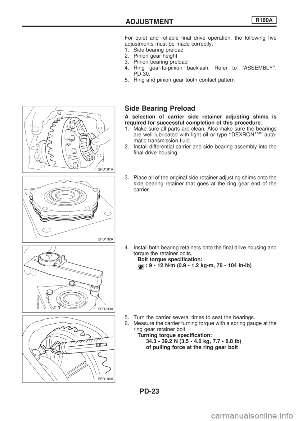
2. Install differential carrier and side bearing assembly into the
final drive housing.
3. Place all of the original side retainer adjusting shims onto the
side bearing retainer that goes at the ring gear end of the
carrier.
4. Install both bearing retainers onto the final drive housing and
torque the retainer bolts.
Bolt torque specification:
:9-12N´m(0.9 - 1.2 kg-m, 78 - 104 in-lb)
5. Turn the carrier several times to seat the bearings.
6. Measure the carrier turning torque with a spring gauge at the
ring gear retainer bolt.
Turning torque specification:
34.3 - 39.2 N (3.5 - 4.0 kg, 7.7 - 8.8 lb)
of pulling force at the ring gear bolt
SPD191A
SPD192A
SPD193A
SPD194A
ADJUSTMENTR180A
PD-23
Page 1127 of 1659
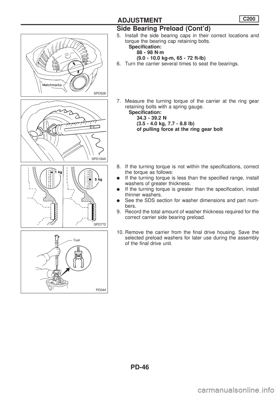
5. Install the side bearing caps in their correct locations and
torque the bearing cap retaining bolts.
Specification:
88-98N´m
(9.0 - 10.0 kg-m, 65 - 72 ft-lb)
6. Turn the carrier several times to seat the bearings.
7. Measure the turning torque of the carrier at the ring gear
retaining bolts with a spring gauge.
Specification:
34.3 - 39.2 N
(3.5 - 4.0 kg, 7.7 - 8.8 lb)
of pulling force at the ring gear bolt
8. If the turning torque is not within the specifications, correct
the torque as follows:
lIf the turning torque is less than the specified range, install
washers of greater thickness.
lIf the turning torque is greater than the specification, install
thinner washers.
lSee the SDS section for washer dimensions and part num-
bers.
9. Record the total amount of washer thickness required for the
correct carrier side bearing preload.
10. Remove the carrier from the final drive housing. Save the
selected preload washers for later use during the assembly
of the final drive unit.
SPD526
SPD194A
SPD772
PD344
ADJUSTMENTC200
Side Bearing Preload (Cont'd)
PD-46
Page 1135 of 1659
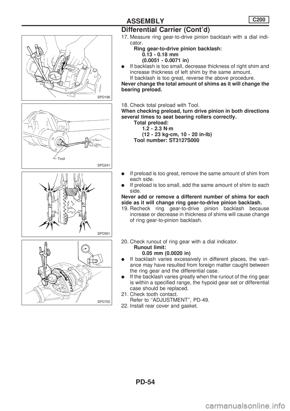
17. Measure ring gear-to-drive pinion backlash with a dial indi-
cator.
Ring gear-to-drive pinion backlash:
0.13 - 0.18 mm
(0.0051 - 0.0071 in)
lIf backlash is too small, decrease thickness of right shim and
increase thickness of left shim by the same amount.
If backlash is too great, reverse the above procedure.
Never change the total amount of shims as it will change the
bearing preload.
18. Check total preload with Tool.
When checking preload, turn drive pinion in both directions
several times to seat bearing rollers correctly.
Total preload:
1.2 - 2.3 N´m
(12 - 23 kg-cm, 10 - 20 in-lb)
Tool number: ST3127S000
lIf preload is too great, remove the same amount of shim from
each side.
lIf preload is too small, add the same amount of shim to each
side.
Never add or remove a different number of shims for each
side as it will change ring gear-to-drive pinion backlash.
19. Recheck ring gear-to-drive pinion backlash because
increase or decrease in thickness of shims will cause change
of ring gear-to-pinion backlash.
20. Check runout of ring gear with a dial indicator.
Runout limit:
0.05 mm (0.0020 in)
lIf backlash varies excessively in different places, the vari-
ance may have resulted from foreign matter caught between
the ring gear and the differential case.
lIf the backlash varies greatly when the runout of the ring gear
is within a specified range, the hypoid gear set or differential
case should be replaced.
21. Check tooth contact.
Refer to ``ADJUSTMENT'', PD-49.
22. Install rear cover and gasket.
SPD196
SPD241
SPD561
SPD702
ASSEMBLYC200
Differential Carrier (Cont'd)
PD-54
Page 1137 of 1659
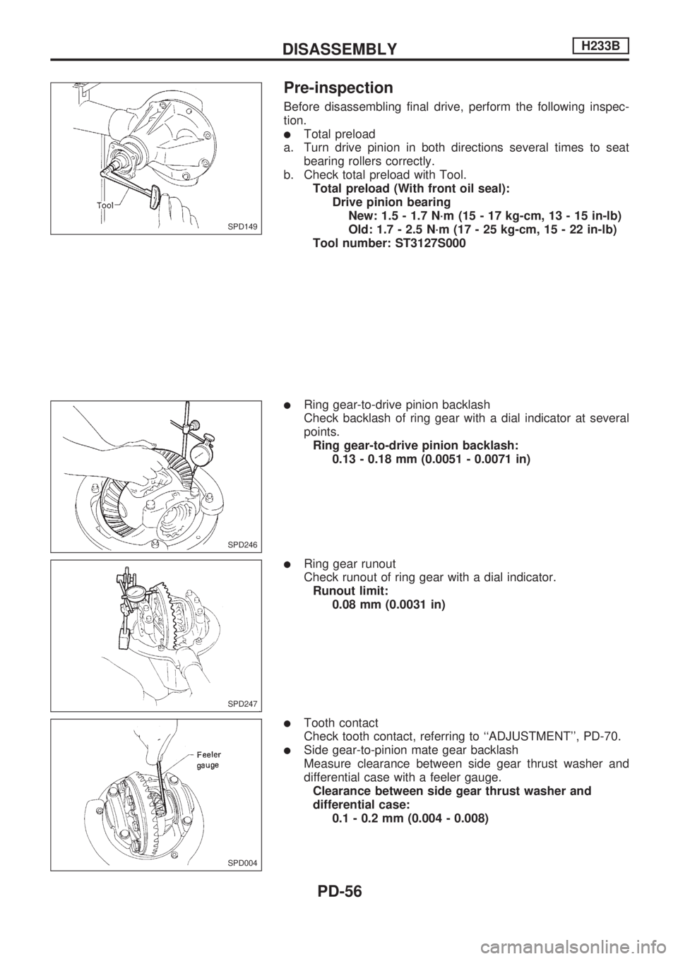
Pre-inspection
Before disassembling final drive, perform the following inspec-
tion.
lTotal preload
a. Turn drive pinion in both directions several times to seat
bearing rollers correctly.
b. Check total preload with Tool.
Total preload (With front oil seal):
Drive pinion bearing
New: 1.5 - 1.7 N´m (15 - 17 kg-cm, 13 - 15 in-lb)
Old: 1.7 - 2.5 N´m (17 - 25 kg-cm, 15 - 22 in-lb)
Tool number: ST3127S000
lRing gear-to-drive pinion backlash
Check backlash of ring gear with a dial indicator at several
points.
Ring gear-to-drive pinion backlash:
0.13 - 0.18 mm (0.0051 - 0.0071 in)
lRing gear runout
Check runout of ring gear with a dial indicator.
Runout limit:
0.08 mm (0.0031 in)
lTooth contact
Check tooth contact, referring to ``ADJUSTMENT'', PD-70.
lSide gear-to-pinion mate gear backlash
Measure clearance between side gear thrust washer and
differential case with a feeler gauge.
Clearance between side gear thrust washer and
differential case:
0.1 - 0.2 mm (0.004 - 0.008)
SPD149
SPD246
SPD247
SPD004
DISASSEMBLYH233B
PD-56
Page 1237 of 1659
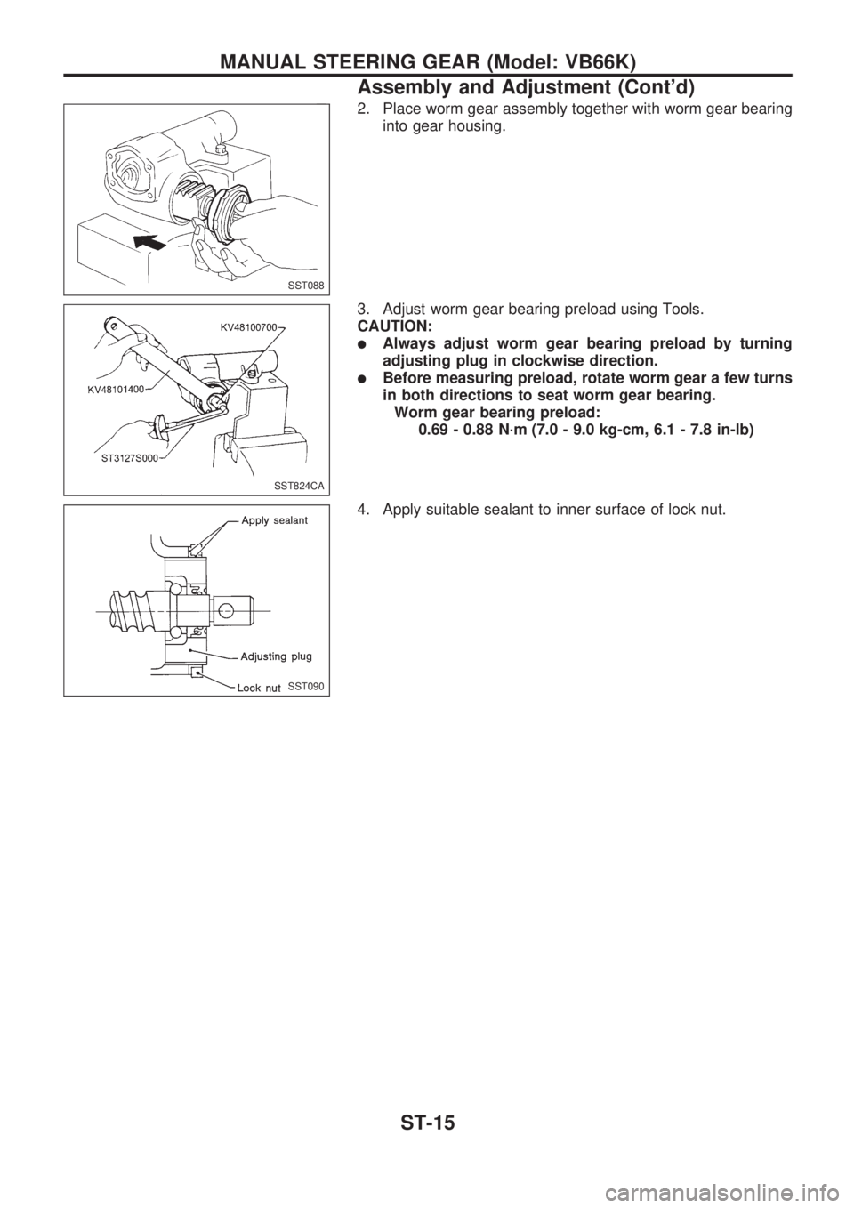
2. Place worm gear assembly together with worm gear bearing
into gear housing.
3. Adjust worm gear bearing preload using Tools.
CAUTION:
lAlways adjust worm gear bearing preload by turning
adjusting plug in clockwise direction.
lBefore measuring preload, rotate worm gear a few turns
in both directions to seat worm gear bearing.
Worm gear bearing preload:
0.69 - 0.88 N´m (7.0 - 9.0 kg-cm, 6.1 - 7.8 in-lb)
4. Apply suitable sealant to inner surface of lock nut.
SST088
SST824CA
SST090
MANUAL STEERING GEAR (Model: VB66K)
Assembly and Adjustment (Cont'd)
ST-15
Page 1239 of 1659
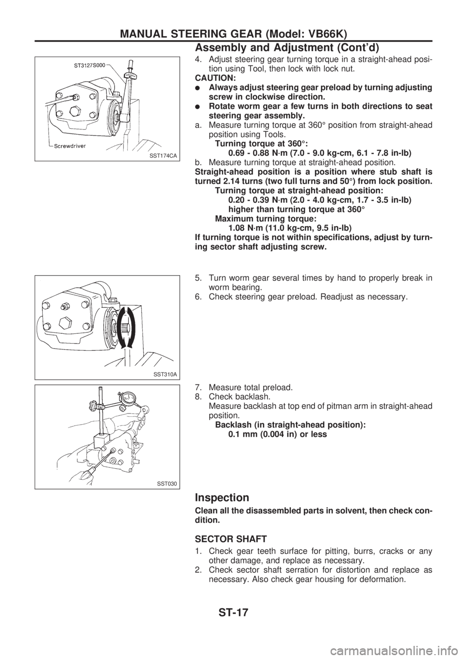
4. Adjust steering gear turning torque in a straight-ahead posi-
tion using Tool, then lock with lock nut.
CAUTION:
lAlways adjust steering gear preload by turning adjusting
screw in clockwise direction.
lRotate worm gear a few turns in both directions to seat
steering gear assembly.
a. Measure turning torque at 360É position from straight-ahead
position using Tools.
Turning torque at 360É:
0.69 - 0.88 N´m (7.0 - 9.0 kg-cm, 6.1 - 7.8 in-lb)
b. Measure turning torque at straight-ahead position.
Straight-ahead position is a position where stub shaft is
turned 2.14 turns (two full turns and 50É) from lock position.
Turning torque at straight-ahead position:
0.20 - 0.39 N´m (2.0 - 4.0 kg-cm, 1.7 - 3.5 in-lb)
higher than turning torque at 360É
Maximum turning torque:
1.08 N´m (11.0 kg-cm, 9.5 in-lb)
If turning torque is not within specifications, adjust by turn-
ing sector shaft adjusting screw.
5. Turn worm gear several times by hand to properly break in
worm bearing.
6. Check steering gear preload. Readjust as necessary.
7. Measure total preload.
8. Check backlash.
Measure backlash at top end of pitman arm in straight-ahead
position.
Backlash (in straight-ahead position):
0.1 mm (0.004 in) or less
Inspection
Clean all the disassembled parts in solvent, then check con-
dition.
SECTOR SHAFT
1. Check gear teeth surface for pitting, burrs, cracks or any
other damage, and replace as necessary.
2. Check sector shaft serration for distortion and replace as
necessary. Also check gear housing for deformation.
SST174CA
SST310A
SST030
MANUAL STEERING GEAR (Model: VB66K)
Assembly and Adjustment (Cont'd)
ST-17
Page 1297 of 1659
HEADLAMP - Headlamp Aiming Control -........... 63
System Description .............................................. 63
Wiring Diagram - H/AIM - .................................... 64
PARKING, LICENSE AND TAIL LAMPS............... 66
Wiring Diagram - TAIL/L -/Except for LHD
Models for Europe ............................................... 66
Wiring Diagram - TAIL/L -/LHD Models for
Europe.................................................................. 68
STOP LAMP............................................................ 70
Wiring Diagram - STOP/L - ................................. 70
BACK-UP LAMP...................................................... 71
Wiring Diagram - BACK/L - ................................. 71
REAR FOG LAMP................................................... 72
Wiring Diagram - R/FOG -/LHD Models .............. 72
Wiring Diagram - R/FOG -/RHD Models ............. 73
TURN SIGNAL AND HAZARD WARNING
LAMPS..................................................................... 74
Schematic ............................................................ 74
Wiring Diagram - TURN -/Except 4WD Models
for Europe ............................................................ 75
Wiring Diagram - TURN -/4WD Models for
Europe.................................................................. 77
Trouble Diagnoses ............................................... 80
Combination Flasher Unit Check ......................... 80
ILLUMINATION........................................................ 81
Wiring Diagram - ILL -/LHD Models .................... 81
Wiring Diagram - ILL -/RHD Models.................... 83
INTERIOR AND SPOT LAMPS............................... 85
Wiring Diagram - INT/L - ..................................... 85
Combination Meter............................................... 87
Schematic ............................................................ 89
Wiring Diagram - METER -/LHD Models............. 90
Wiring Diagram - METER -/RHD Models ............ 93
Unified Control Meter System Description .......... 96
Meter/gauge Operation and Odo/Trip Meter
Segment Check in Diagnosis Mode .................... 96
Flexible Print Circuit (FPC) .................................. 97
Trouble Diagnoses ............................................... 98
Electrical Components Inspection ..................... 103
WARNING LAMPS................................................ 105
Schematic .......................................................... 105
Wiring Diagram - WARN -/LHD Models ............ 106
Wiring Diagram - WARN -/RHD Models............ 111
Electrical Components Inspection ..................... 116
WARNING BUZZER.............................................. 117
Wiring diagram - BUZZER -/LHD Models for
Europe................................................................ 117
Wiring diagram - BUZZER -/RHD Models for
Europe................................................................ 118
Electrical Components Inspection ..................... 119
FRONT WIPER AND WASHER............................ 120
System Description ............................................ 120
Wiring Diagram - WIPER -/LHD Models with
Intermittent ......................................................... 122Wiring Diagram - WIPER -/RHD Models with
Intermittent ......................................................... 124
Trouble Diagnoses ............................................. 126
Wiper Installation and Adjustment ..................... 127
Washer Nozzle Adjustment ............................... 128
Washer Tube Layout ......................................... 128
Wiper Linkage .................................................... 129
HEADLAMP WASHER.......................................... 130
Wiring Diagram - HLC - ..................................... 130
Trouble Diagnoses ............................................. 131
Washer Tube Layout ......................................... 131
Check Valve ....................................................... 131
HORN..................................................................... 132
Wiring Diagram - HORN -.................................. 132
CIGARETTE LIGHTER.......................................... 133
Wiring Diagram - CIGAR - ................................. 133
CLOCK................................................................... 134
Wiring Diagram - CLOCK - ................................ 134
REAR WINDOW DEFOGGER............................... 135
Wiring Diagram - DEF - ..................................... 135
Electrical Components Inspection ..................... 136
Filament Check .................................................. 136
Filament Repair.................................................. 137
AUDIO.................................................................... 138
Wiring Diagram - AUDIO -/LHD Models Type-
2 ......................................................................... 138
Wiring Diagram - AUDIO -/LHD Models Type-
3 ......................................................................... 139
Wiring Diagram - AUDIO -/RHD Models ........... 141
Trouble Diagnoses ............................................. 142
CATS (Code) System/For Europe RHD ............ 143
NATS Audio Link/For Europe LHD (KA24E) ..... 144
AUDIO ANTENNA................................................. 146
Manual Antenna ................................................. 146
Power Antenna/Wiring Diagram - P/ANT - ........ 147
Power Antenna .................................................. 148
POWER DOOR MIRROR...................................... 150
Wiring Diagram - MIRROR -.............................. 150
HEATED SEAT...................................................... 152
Wiring Diagram - H/SEAT - ............................... 152
POWER WINDOW................................................. 154
System Description ............................................ 154
Schematic .......................................................... 156
Wiring Diagram - WINDOW -/LHD Models ....... 157
Wiring Diagram - WINDOW -/RHD Models ....... 161
Trouble Diagnoses ............................................. 165
POWER DOOR LOCK........................................... 166
System Description ............................................ 166
Wiring Diagram - D/LOCK - ............................... 167
Trouble Diagnosis .............................................. 169
MULTI-REMOTE CONTROL SYSTEM/FOR
EUROPE................................................................ 173
System Description ............................................ 173
Schematic .......................................................... 174