1998 NISSAN PICK-UP ground clearance
[x] Cancel search: ground clearancePage 517 of 1659
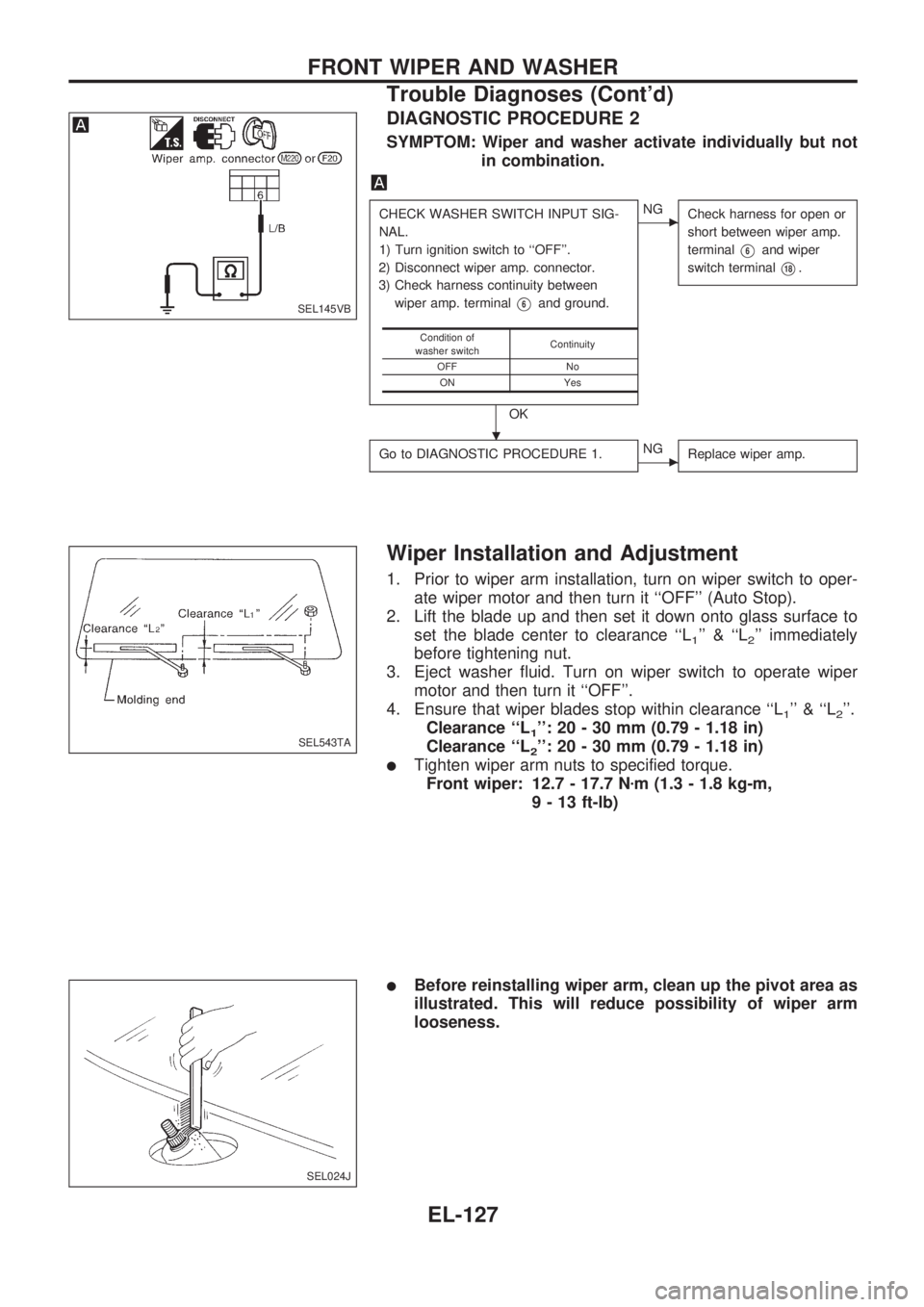
DIAGNOSTIC PROCEDURE 2
SYMPTOM: Wiper and washer activate individually but not
in combination.
CHECK WASHER SWITCH INPUT SIG-
NAL.
1) Turn ignition switch to ``OFF''.
2) Disconnect wiper amp. connector.
3) Check harness continuity between
wiper amp. terminal
V6and ground.
OK
cNG
Check harness for open or
short between wiper amp.
terminal
V6and wiper
switch terminal
V18.
Go to DIAGNOSTIC PROCEDURE 1.cNG
Replace wiper amp.
Condition of
washer switchContinuity
OFF No
ON Yes
Wiper Installation and Adjustment
1. Prior to wiper arm installation, turn on wiper switch to oper-
ate wiper motor and then turn it ``OFF'' (Auto Stop).
2. Lift the blade up and then set it down onto glass surface to
set the blade center to clearance ``L
1'' & ``L2'' immediately
before tightening nut.
3. Eject washer fluid. Turn on wiper switch to operate wiper
motor and then turn it ``OFF''.
4. Ensure that wiper blades stop within clearance ``L
1'' & ``L2''.
Clearance ``L
1'': 20 - 30 mm (0.79 - 1.18 in)
Clearance ``L
2'': 20 - 30 mm (0.79 - 1.18 in)
lTighten wiper arm nuts to specified torque.
Front wiper: 12.7 - 17.7 Nzm (1.3 - 1.8 kg-m,
9 - 13 ft-lb)
lBefore reinstalling wiper arm, clean up the pivot area as
illustrated. This will reduce possibility of wiper arm
looseness.
SEL145VB
SEL543TA
SEL024J
.
FRONT WIPER AND WASHER
Trouble Diagnoses (Cont'd)
EL-127
Page 701 of 1659
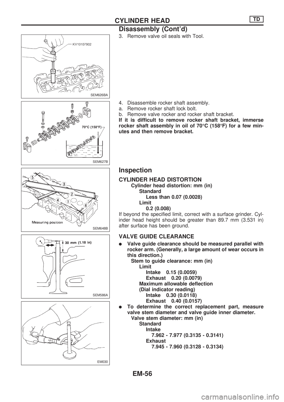
3. Remove valve oil seals with Tool.
4. Disassemble rocker shaft assembly.
a. Remove rocker shaft lock bolt.
b. Remove valve rocker and rocker shaft bracket.
If it is difficult to remove rocker shaft bracket, immerse
rocker shaft assembly in oil of 70ÉC (158ÉF) for a few min-
utes and then remove bracket.
Inspection
CYLINDER HEAD DISTORTION
Cylinder head distortion: mm (in)
Standard
Less than 0.07 (0.0028)
Limit
0.2 (0.008)
If beyond the specified limit, correct with a surface grinder. Cyl-
inder head height should be greater than 89.7 mm (3.531 in)
after surface has been ground.
VALVE GUIDE CLEARANCE
lValve guide clearance should be measured parallel with
rocker arm. (Generally, a large amount of wear occurs in
this direction.)
Stem to guide clearance: mm (in)
Limit
Intake 0.15 (0.0059)
Exhaust 0.20 (0.0079)
Maximum allowable deflection
(Dial indicator reading)
Intake 0.30 (0.0118)
Exhaust 0.40 (0.0157)
lTo determine the correct replacement part, measure
valve stem diameter and valve guide inner diameter.
Valve stem diameter: mm (in)
Standard
Intake
7.962 - 7.977 (0.3135 - 0.3141)
Exhaust
7.945 - 7.960 (0.3128 - 0.3134)
SEM626BA
SEM627B
SEM648B
SEM586A
EM030
CYLINDER HEADTD
Disassembly (Cont'd)
EM-56
Page 848 of 1659
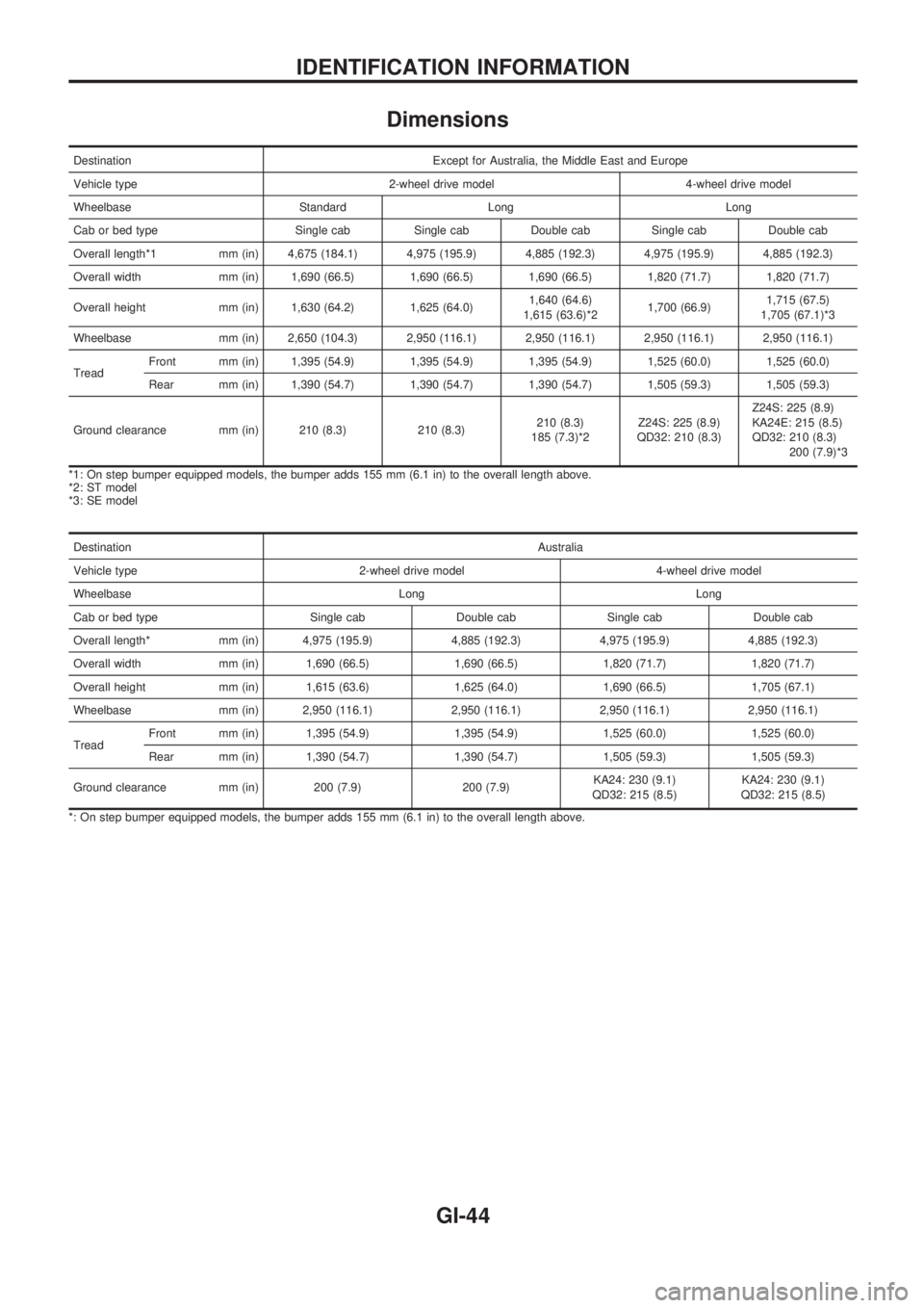
Dimensions
Destination Except for Australia, the Middle East and Europe
Vehicle type 2-wheel drive model 4-wheel drive model
Wheelbase Standard Long Long
Cab or bed type Single cab Single cab Double cab Single cab Double cab
Overall length*1 mm (in) 4,675 (184.1) 4,975 (195.9) 4,885 (192.3) 4,975 (195.9) 4,885 (192.3)
Overall width mm (in) 1,690 (66.5) 1,690 (66.5) 1,690 (66.5) 1,820 (71.7) 1,820 (71.7)
Overall height mm (in) 1,630 (64.2) 1,625 (64.0)1,640 (64.6)
1,615 (63.6)*21,700 (66.9)1,715 (67.5)
1,705 (67.1)*3
Wheelbase mm (in) 2,650 (104.3) 2,950 (116.1) 2,950 (116.1) 2,950 (116.1) 2,950 (116.1)
TreadFront mm (in) 1,395 (54.9) 1,395 (54.9) 1,395 (54.9) 1,525 (60.0) 1,525 (60.0)
Rear mm (in) 1,390 (54.7) 1,390 (54.7) 1,390 (54.7) 1,505 (59.3) 1,505 (59.3)
Ground clearance mm (in) 210 (8.3) 210 (8.3)210 (8.3)
185 (7.3)*2Z24S: 225 (8.9)
QD32: 210 (8.3)Z24S: 225 (8.9)
KA24E: 215 (8.5)
QD32: 210 (8.3)
200 (7.9)*3
*1: On step bumper equipped models, the bumper adds 155 mm (6.1 in) to the overall length above.
*2: ST model
*3: SE model
DestinationAustralia
Vehicle type 2-wheel drive model 4-wheel drive model
Wheelbase Long Long
Cab or bed type Single cab Double cab Single cab Double cab
Overall length* mm (in) 4,975 (195.9) 4,885 (192.3) 4,975 (195.9) 4,885 (192.3)
Overall width mm (in) 1,690 (66.5) 1,690 (66.5) 1,820 (71.7) 1,820 (71.7)
Overall height mm (in) 1,615 (63.6) 1,625 (64.0) 1,690 (66.5) 1,705 (67.1)
Wheelbase mm (in) 2,950 (116.1) 2,950 (116.1) 2,950 (116.1) 2,950 (116.1)
TreadFront mm (in) 1,395 (54.9) 1,395 (54.9) 1,525 (60.0) 1,525 (60.0)
Rear mm (in) 1,390 (54.7) 1,390 (54.7) 1,505 (59.3) 1,505 (59.3)
Ground clearance mm (in) 200 (7.9) 200 (7.9)KA24: 230 (9.1)
QD32: 215 (8.5)KA24: 230 (9.1)
QD32: 215 (8.5)
*: On step bumper equipped models, the bumper adds 155 mm (6.1 in) to the overall length above.
IDENTIFICATION INFORMATION
GI-44
Page 849 of 1659
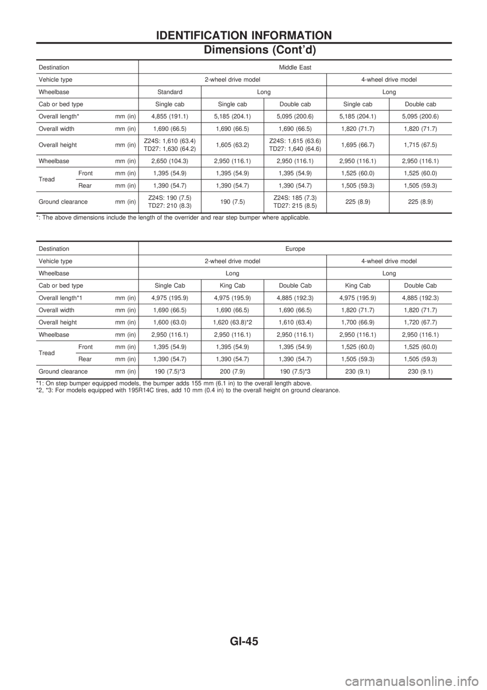
DestinationMiddle East
Vehicle type 2-wheel drive model 4-wheel drive model
Wheelbase Standard Long Long
Cab or bed type Single cab Single cab Double cab Single cab Double cab
Overall length* mm (in) 4,855 (191.1) 5,185 (204.1) 5,095 (200.6) 5,185 (204.1) 5,095 (200.6)
Overall width mm (in) 1,690 (66.5) 1,690 (66.5) 1,690 (66.5) 1,820 (71.7) 1,820 (71.7)
Overall height mm (in)Z24S: 1,610 (63.4)
TD27: 1,630 (64.2)1,605 (63.2)Z24S: 1,615 (63.6)
TD27: 1,640 (64.6)1,695 (66.7) 1,715 (67.5)
Wheelbase mm (in) 2,650 (104.3) 2,950 (116.1) 2,950 (116.1) 2,950 (116.1) 2,950 (116.1)
TreadFront mm (in) 1,395 (54.9) 1,395 (54.9) 1,395 (54.9) 1,525 (60.0) 1,525 (60.0)
Rear mm (in) 1,390 (54.7) 1,390 (54.7) 1,390 (54.7) 1,505 (59.3) 1,505 (59.3)
Ground clearance mm (in)Z24S: 190 (7.5)
TD27: 210 (8.3)190 (7.5)Z24S: 185 (7.3)
TD27: 215 (8.5)225 (8.9) 225 (8.9)
*: The above dimensions include the length of the overrider and rear step bumper where applicable.
DestinationEurope
Vehicle type 2-wheel drive model 4-wheel drive model
Wheelbase Long Long
Cab or bed type Single Cab King Cab Double Cab King Cab Double Cab
Overall length*1 mm (in) 4,975 (195.9) 4,975 (195.9) 4,885 (192.3) 4,975 (195.9) 4,885 (192.3)
Overall width mm (in) 1,690 (66.5) 1,690 (66.5) 1,690 (66.5) 1,820 (71.7) 1,820 (71.7)
Overall height mm (in) 1,600 (63.0) 1,620 (63.8)*2 1,610 (63.4) 1,700 (66.9) 1,720 (67.7)
Wheelbase mm (in) 2,950 (116.1) 2,950 (116.1) 2,950 (116.1) 2,950 (116.1) 2,950 (116.1)
TreadFront mm (in) 1,395 (54.9) 1,395 (54.9) 1,395 (54.9) 1,525 (60.0) 1,525 (60.0)
Rear mm (in) 1,390 (54.7) 1,390 (54.7) 1,390 (54.7) 1,505 (59.3) 1,505 (59.3)
Ground clearance mm (in) 190 (7.5)*3 200 (7.9) 190 (7.5)*3 230 (9.1) 230 (9.1)
*1: On step bumper equipped models, the bumper adds 155 mm (6.1 in) to the overall length above.
*2, *3: For models equipped with 195R14C tires, add 10 mm (0.4 in) to the overall height on ground clearance.
IDENTIFICATION INFORMATION
Dimensions (Cont'd)
GI-45
Page 866 of 1659

EVAP vapor lines inspection ....................... MA-22
Electrical diagnoses ...................................... GI-21
Engine compartment .................................... BT-44
Engine control module (ECM) ....................... EC-5
Engine coolant temperature sensor
(ECTS) (KA24 engine) ............................. EC-95
Engine coolant temperature sensor
(ECTS) (TD25 engine) ........................... EC-209
Engine oil filter replacement
(KA24 engine).......................................... MA-20
Engine oil filter replacement
(TD25 engine).......................................... MA-24
Engine oil precautions .................................... GI-4
Engine oil replacement
(KA24 engine).......................................... MA-19
Engine oil replacement
(TD25 engine).......................................... MA-24
Engine outer component parts
(KA24 engine)............................................ EM-9
Engine outer component parts
(TD25 engine).......................................... EM-49
Engine removal (KA24 engine) ................... EM-36
Engine removal (TD25 engine) ................... EM-69
Engine room - See Engine
compartment............................................. BT-44
Engine speed sensor ................................. EC-219
Evaporative emission (EVAP) system ......... EC-19
Exhaust system inspection.......................... MA-32
Exhaust system .............................................. FE-5
Exterior ......................................................... BT-24
F
F/PUMP - Wiring diagram...........................EC-153
FCUT - Wiring diagram ............................. EC-225
FICD - Wiring diagram (KA24 engine) ...... EC-168
FICD - Wiring diagram (TD25 engine) ...... EC-230
Fan switch.................................................... HA-43
Fast idle cam (FIC) inspection and
adjustment................................................ EC-24
Final drive disassembly (C200) ................... PD-34
Final drive disassembly (H233B)................. PD-56
Final drive pre-inspection (C200) ................ PD-34
Final drive pre-inspection (H233B) .............. PD-56
Final drive removal and installation ............. PD-15
Floor trim ...................................................... BT-15
Flow charts.................................................... GI-31
Fluids ........................................................... MA-12
Flywheel (clutch) .......................................... CL-12
Flywheel runout (KA24 engine)................... EM-45
Flywheel runout (TD25 engine)................... EM-80
Fog lamp, rear .............................................. EL-72
Fork rod (M/T) (FS5R30A) .......................... MT-38
Fork rod (M/T) (FS5W71C) ......................... MT-17
Front axle ..................................................... FA-12
Front bumper.................................................. BT-5
Front case (Transfer) ..................................... TF-8
Front combination lamp removal and
installation................................................... BT-5Front disc brake ........................................... BR-21
Front door..................................................... BT-10
Front drive shaft (Transfer) ............................ TF-9
Front final drive disassembly (4WD) ........... PD-17
Front final drive pre-inspection (4WD) ........ PD-17
Front final drive removal and installa-
tion (4WD) ................................................ PD-14
Front seat belt................................................ RS-3
Front seat ..................................................... BT-30
Front suspension.......................................... FA-26
Front washer .............................................. EL-120
Front wiper ................................................. EL-120
Fuel check valve .......................................... EC-20
Fuel cut control (at no load & high
engine speed) (KA24 engine) .................. EC-18
Fuel cut control (at no load & high
engine speed) ........................................ EC-225
Fuel filter replacement (KA24 engine) ........ MA-18
Fuel filter replacement (TD25 engine) ........ MA-27
Fuel injector ............................................... EC-144
Fuel line inspection (KA24 engine) ............. MA-18
Fuel line inspection (TD25 engine) ............. MA-28
Fuel precautions ............................................. GI-5
Fuel pressure check .................................... EC-22
Fuel pressure release .................................. EC-22
Fuel pump .................................................. EC-151
Fuel pump relay ......................................... EC-156
Fuel system .................................................... FE-3
Fuel tank vacuum relief valve...................... EC-20
Fuse block.................................................. Foldout
Fuse.............................................................. EL-13
Fusible link ................................................... EL-13G
GLOW - Wiring diagram .............................EC-197
Garage jack and safety stand....................... GI-49
Gear components (M/T) (FS5R30A) ........... MT-36
Gear components (M/T) (FS5W71C) .......... MT-15
Glass ............................................................ BT-10
Glow plug ................................................... EC-208
Glow relay .................................................. EC-208
Grease ......................................................... MA-12
Ground clearance ......................................... GI-44
Ground distribution ....................................... EL-14
H
H/AIM - Wiring diagram .................................EL-64
H/LAMP - Wiring diagram ............................ EL-44
H02S - Wiring diagram .............................. EC-124
HFC134a (R134a) system precaution ........... HA-2
HFC134a (R134a) system service
procedure ................................................. HA-48
HFC134a (R134a) system service
tools............................................................ HA-8
HFC134a system service equipment
precaution ................................................ HA-10
ALPHABETICAL INDEX
IDX-4
Page 1425 of 1659
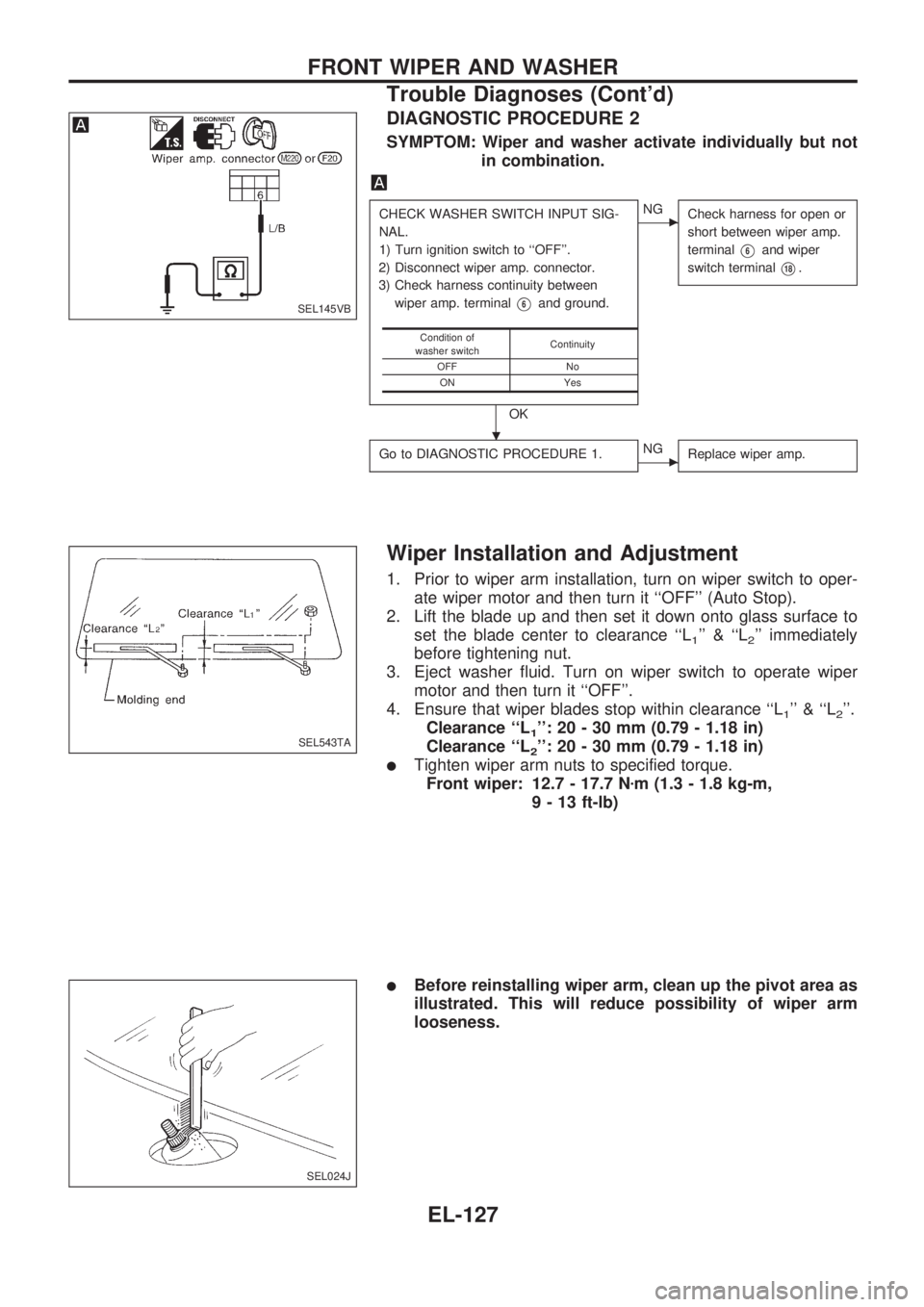
DIAGNOSTIC PROCEDURE 2
SYMPTOM: Wiper and washer activate individually but not
in combination.
CHECK WASHER SWITCH INPUT SIG-
NAL.
1) Turn ignition switch to ``OFF''.
2) Disconnect wiper amp. connector.
3) Check harness continuity between
wiper amp. terminal
V6and ground.
OK
cNG
Check harness for open or
short between wiper amp.
terminal
V6and wiper
switch terminal
V18.
Go to DIAGNOSTIC PROCEDURE 1.cNG
Replace wiper amp.
Condition of
washer switchContinuity
OFF No
ON Yes
Wiper Installation and Adjustment
1. Prior to wiper arm installation, turn on wiper switch to oper-
ate wiper motor and then turn it ``OFF'' (Auto Stop).
2. Lift the blade up and then set it down onto glass surface to
set the blade center to clearance ``L
1'' & ``L2'' immediately
before tightening nut.
3. Eject washer fluid. Turn on wiper switch to operate wiper
motor and then turn it ``OFF''.
4. Ensure that wiper blades stop within clearance ``L
1'' & ``L2''.
Clearance ``L
1'': 20 - 30 mm (0.79 - 1.18 in)
Clearance ``L
2'': 20 - 30 mm (0.79 - 1.18 in)
lTighten wiper arm nuts to specified torque.
Front wiper: 12.7 - 17.7 Nzm (1.3 - 1.8 kg-m,
9 - 13 ft-lb)
lBefore reinstalling wiper arm, clean up the pivot area as
illustrated. This will reduce possibility of wiper arm
looseness.
SEL145VB
SEL543TA
SEL024J
.
FRONT WIPER AND WASHER
Trouble Diagnoses (Cont'd)
EL-127
Page 1609 of 1659
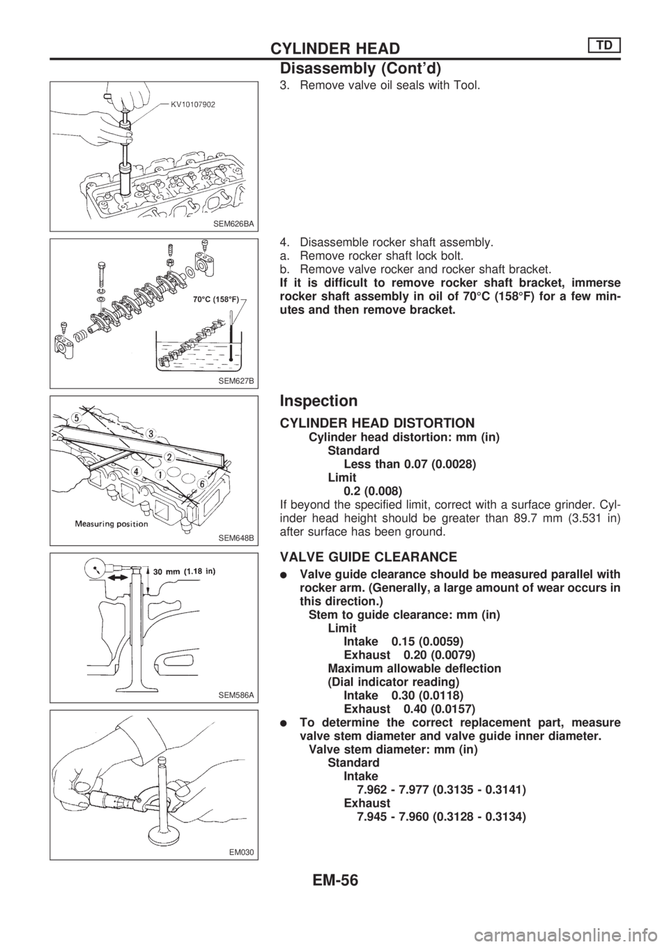
3. Remove valve oil seals with Tool.
4. Disassemble rocker shaft assembly.
a. Remove rocker shaft lock bolt.
b. Remove valve rocker and rocker shaft bracket.
If it is difficult to remove rocker shaft bracket, immerse
rocker shaft assembly in oil of 70ÉC (158ÉF) for a few min-
utes and then remove bracket.
Inspection
CYLINDER HEAD DISTORTION
Cylinder head distortion: mm (in)
Standard
Less than 0.07 (0.0028)
Limit
0.2 (0.008)
If beyond the specified limit, correct with a surface grinder. Cyl-
inder head height should be greater than 89.7 mm (3.531 in)
after surface has been ground.
VALVE GUIDE CLEARANCE
lValve guide clearance should be measured parallel with
rocker arm. (Generally, a large amount of wear occurs in
this direction.)
Stem to guide clearance: mm (in)
Limit
Intake 0.15 (0.0059)
Exhaust 0.20 (0.0079)
Maximum allowable deflection
(Dial indicator reading)
Intake 0.30 (0.0118)
Exhaust 0.40 (0.0157)
lTo determine the correct replacement part, measure
valve stem diameter and valve guide inner diameter.
Valve stem diameter: mm (in)
Standard
Intake
7.962 - 7.977 (0.3135 - 0.3141)
Exhaust
7.945 - 7.960 (0.3128 - 0.3134)
SEM626BA
SEM627B
SEM648B
SEM586A
EM030
CYLINDER HEADTD
Disassembly (Cont'd)
EM-56