1998 NISSAN PICK-UP radiator
[x] Cancel search: radiatorPage 13 of 1659

INSPECTION
1. Ensure vehicle is unladen condition*.
* Fuel, radiator coolant and engine oil full. Spare tire, jack,
hand tools and mats in designated positions.
2. Have a driver sit in the driver's seat and one person sit on
the rear of the vehicle. Then have the person on the rear of
the vehicle slowly get off. This is necessary to stabilize sus-
pension deflection.
3. Adjust length ``L'' as follows:
a. Loosen stopper bolt locknut (2WD JIDOSHA KIKI make).
b. Pull lever against stopper bolt and adjust by turning stopper
bolt.
c. Tighten stopper bolt locknut (2WD JIDOSHA KIKI make).
Length ``L'':
2WD models
Approx. 187.3 mm (7.37 in)
4WD models
Approx. 158.1 mm (6.22 in)
4. Install pressure gauge to front and rear brake air bleeder.
5. Bleed air from the Tool.
6. Raise front brake pressure to 4,904 kPa (49.0 bar, 50
kg/cm
2, 711 psi) and 9,807 kPa (98.1 bar, 100 kg/cm2, 1,422
psi) and check rear brake pressure.
Rear brake pressure:
Refer to table below.
7. Set down weight slowly over axle center so that sensor
spring length becomes the same as when in loaded condi-
tion (refer to table below). Check rear brake pressure in the
same way described in step 6.
Unit: kPa (bar, kg/cm2, psi)
Front brake
pressureRear brake pressure
2WD 4WD
Unladen
condition
L = 187.3 mm
(7.37 in)Loaded
condition
L = 204.0 mm
(8.03 in)Unladen
condition
L = 158.1 mm
(6.22 in)Loaded
condition
L = 184.0 mm
(7.24 in)
4,904
(49.0, 50, 711)1,667 - 2,648
(16.7 - 26.5, 17
- 27, 242 - 384)3,334 - 4,315
(33.3 - 43.2, 34
- 44, 483 - 626)1,863 - 2,844
(18.6 - 28.4, 19
- 29, 270 - 412)3,334 - 4,315
(33.3 - 43.2, 34
- 44, 483 - 626)
9,807
(98.1, 100,
1,422)2,844 - 3,825
(28.4 - 38.2, 29
- 39, 412 - 555)3,629 - 5,590
(36.3 - 55.9, 37
- 57, 526 - 811)2,059 - 4,021
(20.6 - 40.2, 21
- 41, 299 - 583)3,629 - 5,590
(36.3 - 55.9, 37
- 57, 526 - 811)
SBR967D
SBR968D
SBR013B
SBR014B
CONTROL VALVE
Load Sensing Valve (Cont'd)
BR-9
Page 215 of 1659
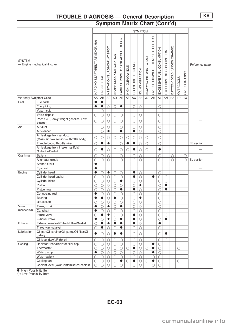
SYSTEM
Ð Engine mechanical & otherSYMPTOM
Reference page
HARD/NO START/RESTART (EXCP. HA)
ENGINE STALL
HESITATION/SURGING/FLAT SPOT
SPARK KNOCK/DETONATION
LACK OF POWER/POOR ACCELERATION
HIGH IDLE/LOW IDLE
ROUGH IDLE/HUNTING
IDLING VIBRATION
SLOW/NO RETURN TO IDLE
OVERHEATS/WATER TEMPERATURE HIGH
EXCESSIVE FUEL CONSUMPTION
EXCESSIVE OIL CONSUMPTION
BATTERY DEAD (UNDER CHARGE)
OVERCOOLS
OVERCHARGING
Warranty Symptom Code AA AB AC AD AE AF AG AH AJ AK AL AM HA 1P 1X
Fuel Fuel tank
ll
Ð Fuel piping
lljjljj j
Vapor lockj
Valve depositjjjjj jj j
Poor fuel (Heavy weight gasoline, Low
octane)jjjjj jj j
Air Air ductjjjjj j
Air cleanerj
llljj
Air leakage from air duct
(Mass air flow sensor Ð throttle body)jjjjjjjjj j
Throttle body, Throttle wirej
lljlljj jFE section
Air leakage from intake manifold/
Collector/Gasketj
ljjjjljjlÐ
Cranking Batteryjjjjjj jjj
EL section Alternator circuitjjjjjj jjj
Starter circuit
l
FlywheellÐ
Engine Cylinder head
ljljjljj
Ð Cylinder head gasketjjjjj
ljljj
Cylinder blockjjjj
ljj jj
Pistonjjjjj j
ljl
Piston ringjjjjlljjl
Connecting rodljjjj jj j
Bearing
lljljjlj
Crankshaftjjjjj jj j
Valve
mechanismTiming chain
ljljljj j
Camshaft
ljjjj jj j
Intake valvej
lljjljjj
Exhaust valve
ljljlljjl
Exhaust Exhaust manifold/Tube/Muffler/Gasketjllll ljl
Three way catalystjljjljj j
Lubrication Oil pan/Oil strainer/Oil pump/Oil filter/Oil
gallery
ljjlljj jl
Oil level (Low)/Filthy oiljjjjj jj jj
Cooling Radiator/Hose/Radiator filler capjjjjj jj
lj
Thermostatjjjjjj
ljjljj
Water pump
ljjjj jjlj
Water galleryjjjjj jj jj
Cooling fanjjjj
ljljjljj
Coolant level (low)/Contaminated coolantjjjjj jj jj
l; High Possibility Item
j; Low Possibility Item
TROUBLE DIAGNOSIS Ð General DescriptionKA
Symptom Matrix Chart (Cont'd)
EC-63
Page 258 of 1659
Overheat
ON BOARD DIAGNOSIS LOGIC
If the cooling fan or another component in the cooling system malfunctions, the engine coolant temperature
will rise.
When the engine coolant temperature reaches an abnormally high temperature condition, a malfunction is
indicated.
Diagnostic trouble
code No.Malfunction is detected when ...Check Items
(Possible Cause)
28
lEngine coolant temperature reaches an abnormally
high temperature.lCooling fan
lRadiator hose
lRadiator
lRadiator cap
lWater pump
lThermostat
For more information, refer to ``MAIN 12
CAUSES OF OVERHEATING'', EC-108.
CAUTION:
When a malfunction is indicated, be sure to replace the coolant following the procedure in MA sec-
tion (``Changing Engine Coolant'', ``ENGINE MAINTENANCE''). Also, replace the engine oil.
lFill radiator with coolant up to specified level with a filling speed of 2 liters per minute like pour-
ing coolant by kettle. Be sure to use coolant with the proper mixture ratio. Refer to MA section
(``Anti-freeze Coolant Mixture Ratio'', ``RECOMMENDED FLUIDS AND LUBRICANTS'').
lAfter refilling coolant, run engine to ensure that no water-flow noise is emitted.
OVERALL FUNCTION CHECK
WARNING:
Never remove the radiator cap when the engine is hot. Seri-
ous burns could be caused by high pressure fluid escaping
from the radiator.
Wrap a thick cloth around cap. Carefully remove the cap by
turning it a quarter turn to allow built-up pressure to escape.
Then turn the cap all the way off.
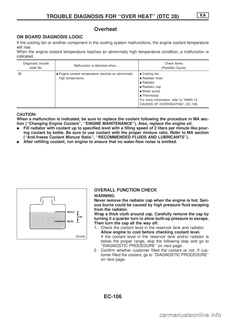
1. Check the coolant level in the reservoir tank and radiator.
Allow engine to cool before checking coolant level.
If the coolant level in the reservoir tank and/or radiator is
below the proper range, skip the following step and go to
``DIAGNOSTIC PROCEDURE'' on next page.
2. Confirm whether customer filled the coolant or not. If cus-
tomer filled the coolant, go to ``DIAGNOSTIC PROCEDURE''
on next page.
AEC640
TROUBLE DIAGNOSIS FOR ``OVER HEAT'' (DTC 28)KA
EC-106
Page 259 of 1659
DIAGNOSTIC PROCEDURE
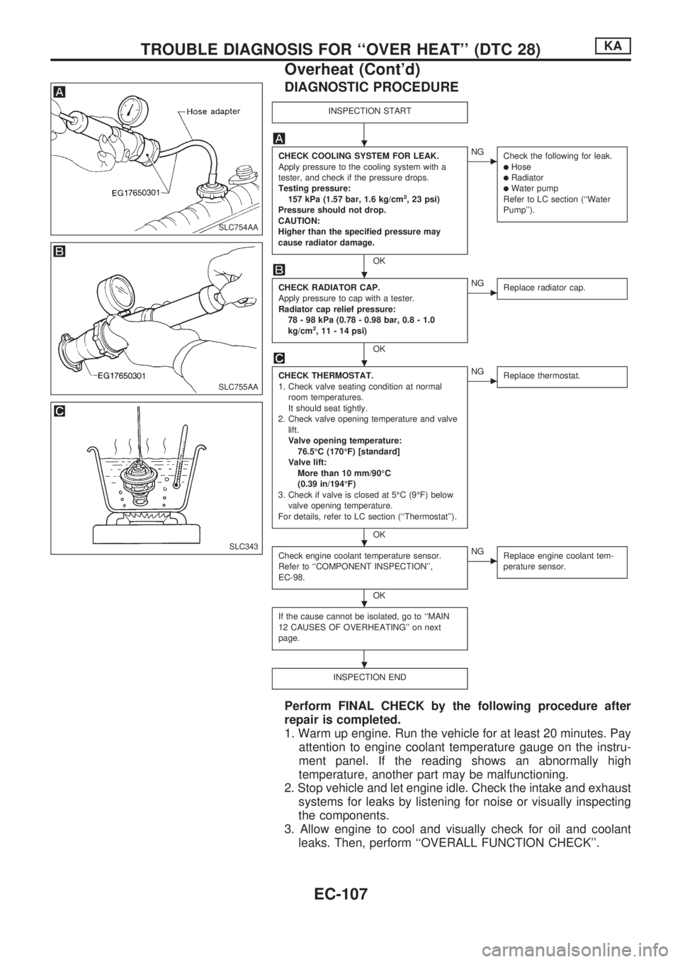
INSPECTION START
CHECK COOLING SYSTEM FOR LEAK.
Apply pressure to the cooling system with a
tester, and check if the pressure drops.
Testing pressure:
157 kPa (1.57 bar, 1.6 kg/cm
2, 23 psi)
Pressure should not drop.
CAUTION:
Higher than the specified pressure may
cause radiator damage.
OK
cNG
Check the following for leak.
lHoselRadiatorlWater pump
Refer to LC section (``Water
Pump'').
CHECK RADIATOR CAP.
Apply pressure to cap with a tester.
Radiator cap relief pressure:
78 - 98 kPa (0.78 - 0.98 bar, 0.8 - 1.0
kg/cm
2, 11 - 14 psi)
OK
cNG
Replace radiator cap.
CHECK THERMOSTAT.
1. Check valve seating condition at normal
room temperatures.
It should seat tightly.
2. Check valve opening temperature and valve
lift.
Valve opening temperature:
76.5ÉC (170ÉF) [standard]
Valve lift:
More than 10 mm/90ÉC
(0.39 in/194ÉF)
3. Check if valve is closed at 5ÉC (9ÉF) below
valve opening temperature.
For details, refer to LC section (``Thermostat'').
OK
cNG
Replace thermostat.
Check engine coolant temperature sensor.
Refer to ``COMPONENT INSPECTION'',
EC-98.
OK
cNG
Replace engine coolant tem-
perature sensor.
If the cause cannot be isolated, go to ``MAIN
12 CAUSES OF OVERHEATING'' on next
page.
INSPECTION END
Perform FINAL CHECK by the following procedure after
repair is completed.
1. Warm up engine. Run the vehicle for at least 20 minutes. Pay
attention to engine coolant temperature gauge on the instru-
ment panel. If the reading shows an abnormally high
temperature, another part may be malfunctioning.
2. Stop vehicle and let engine idle. Check the intake and exhaust
systems for leaks by listening for noise or visually inspecting
the components.
3. Allow engine to cool and visually check for oil and coolant
leaks. Then, perform ``OVERALL FUNCTION CHECK''.
SLC754AA
SLC755AA
SLC343
.
.
.
.
.
.
TROUBLE DIAGNOSIS FOR ``OVER HEAT'' (DTC 28)KA
Overheat (Cont'd)
EC-107
Page 260 of 1659
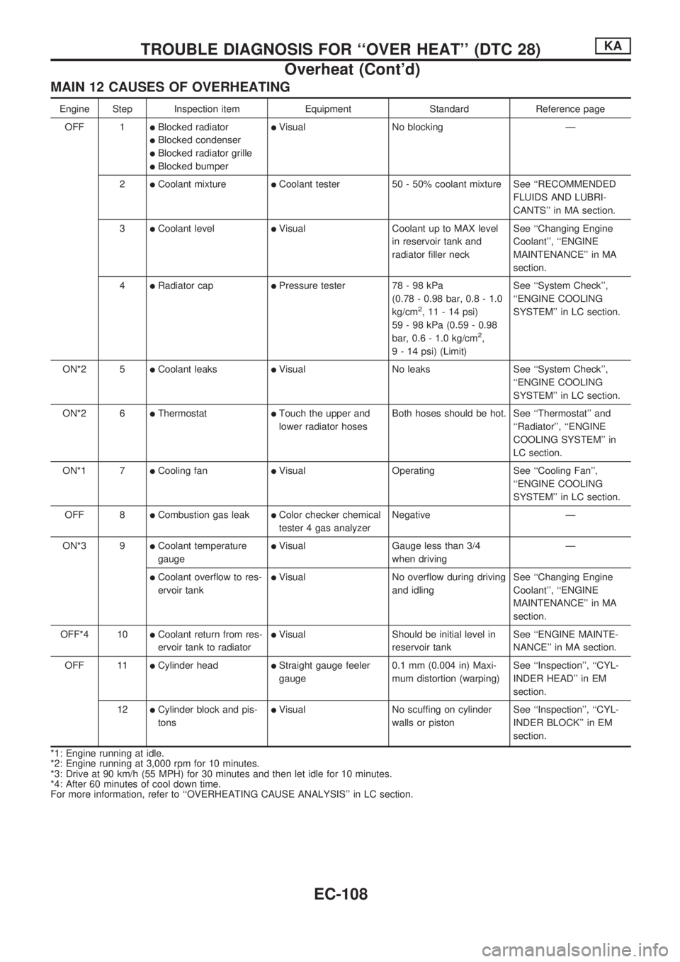
MAIN 12 CAUSES OF OVERHEATING
Engine Step Inspection item Equipment Standard Reference page
OFF 1
lBlocked radiator
lBlocked condenser
lBlocked radiator grille
lBlocked bumper
lVisual No blocking Ð
2
lCoolant mixturelCoolant tester 50 - 50% coolant mixture See ``RECOMMENDED
FLUIDS AND LUBRI-
CANTS'' in MA section.
3
lCoolant levellVisual Coolant up to MAX level
in reservoir tank and
radiator filler neckSee ``Changing Engine
Coolant'', ``ENGINE
MAINTENANCE'' in MA
section.
4
lRadiator caplPressure tester 78 - 98 kPa
(0.78 - 0.98 bar, 0.8 - 1.0
kg/cm
2, 11 - 14 psi)
59 - 98 kPa (0.59 - 0.98
bar, 0.6 - 1.0 kg/cm
2,
9 - 14 psi) (Limit)See ``System Check'',
``ENGINE COOLING
SYSTEM'' in LC section.
ON*2 5
lCoolant leakslVisual No leaks See ``System Check'',
``ENGINE COOLING
SYSTEM'' in LC section.
ON*2 6
lThermostatlTouch the upper and
lower radiator hosesBoth hoses should be hot. See ``Thermostat'' and
``Radiator'', ``ENGINE
COOLING SYSTEM'' in
LC section.
ON*1 7
lCooling fanlVisual Operating See ``Cooling Fan'',
``ENGINE COOLING
SYSTEM'' in LC section.
OFF 8
lCombustion gas leaklColor checker chemical
tester 4 gas analyzerNegative Ð
ON*3 9
lCoolant temperature
gaugelVisual Gauge less than 3/4
when drivingÐ
lCoolant overflow to res-
ervoir tanklVisual No overflow during driving
and idlingSee ``Changing Engine
Coolant'', ``ENGINE
MAINTENANCE'' in MA
section.
OFF*4 10
lCoolant return from res-
ervoir tank to radiatorlVisual Should be initial level in
reservoir tankSee ``ENGINE MAINTE-
NANCE'' in MA section.
OFF 11
lCylinder headlStraight gauge feeler
gauge0.1 mm (0.004 in) Maxi-
mum distortion (warping)See ``Inspection'', ``CYL-
INDER HEAD'' in EM
section.
12
lCylinder block and pis-
tonslVisual No scuffing on cylinder
walls or pistonSee ``Inspection'', ``CYL-
INDER BLOCK'' in EM
section.
*1: Engine running at idle.
*2: Engine running at 3,000 rpm for 10 minutes.
*3: Drive at 90 km/h (55 MPH) for 30 minutes and then let idle for 10 minutes.
*4: After 60 minutes of cool down time.
For more information, refer to ``OVERHEATING CAUSE ANALYSIS'' in LC section.
TROUBLE DIAGNOSIS FOR ``OVER HEAT'' (DTC 28)KA
Overheat (Cont'd)
EC-108
Page 658 of 1659
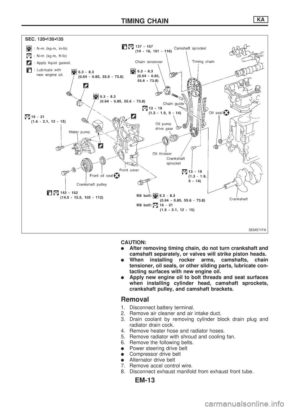
CAUTION:
lAfter removing timing chain, do not turn crankshaft and
camshaft separately, or valves will strike piston heads.
lWhen installing rocker arms, camshafts, chain
tensioner, oil seals, or other sliding parts, lubricate con-
tacting surfaces with new engine oil.
lApply new engine oil to bolt threads and seat surfaces
when installing cylinder head, camshaft sprockets,
crankshaft pulley, and camshaft brackets.
Removal
1. Disconnect battery terminal.
2. Remove air cleaner and air intake duct.
3. Drain coolant by removing cylinder block drain plug and
radiator drain cock.
4. Remove heater hose and radiator hoses.
5. Remove radiator with shroud and cooling fan.
6. Remove the following belts.
lPower steering drive belt
lCompressor drive belt
lAlternator drive belt
7. Remove accel control wire.
8. Disconnect exhaust manifold from exhaust front tube.
SEM571FA
TIMING CHAINKA
EM-13
Page 667 of 1659
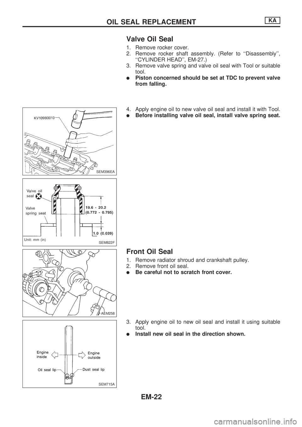
Valve Oil Seal
1. Remove rocker cover.
2. Remove rocker shaft assembly. (Refer to ``Disassembly'',
``CYLINDER HEAD'', EM-27.)
3. Remove valve spring and valve oil seal with Tool or suitable
tool.
lPiston concerned should be set at TDC to prevent valve
from falling.
4. Apply engine oil to new valve oil seal and install it with Tool.
lBefore installing valve oil seal, install valve spring seat.
Front Oil Seal
1. Remove radiator shroud and crankshaft pulley.
2. Remove front oil seal.
lBe careful not to scratch front cover.
3. Apply engine oil to new oil seal and install it using suitable
tool.
lInstall new oil seal in the direction shown.
SEM396EA
SEM822F
.Unit: mm (in)
AEM258
SEM715A
OIL SEAL REPLACEMENTKA
EM-22
Page 670 of 1659
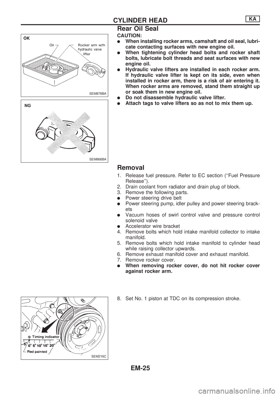
CAUTION:
lWhen installing rocker arms, camshaft and oil seal, lubri-
cate contacting surfaces with new engine oil.
lWhen tightening cylinder head bolts and rocker shaft
bolts, lubricate bolt threads and seat surfaces with new
engine oil.
lHydraulic valve lifters are installed in each rocker arm.
If hydraulic valve lifter is kept on its side, even when
installed in rocker arm, there is a risk of air entering it.
When rocker arms are removed, stand them straight up
or soak them in new engine oil.
lDo not disassemble hydraulic valve lifter.
lAttach tags to valve lifters so as not to mix them up.
Removal
1. Release fuel pressure. Refer to EC section (``Fuel Pressure
Release'').
2. Drain coolant from radiator and drain plug of block.
3. Remove the following parts.
lPower steering drive belt
lPower steering pump, idler pulley and power steering brack-
ets
lVacuum hoses of swirl control valve and pressure control
solenoid valve
lAccelerator wire bracket
4. Remove bolts which hold intake manifold collector to intake
manifold.
5. Remove bolts which hold intake manifold to cylinder head
while raising collector upwards.
6. Remove exhaust manifold cover and exhaust manifold.
7. Remove rocker cover.
lWhen removing rocker cover, do not hit rocker cover
against rocker arm.
8. Set No. 1 piston at TDC on its compression stroke.
SEM878BA
SEM868BA
.NG
SEM216C
CYLINDER HEADKA
Rear Oil Seal
EM-25