Page 18 of 1659

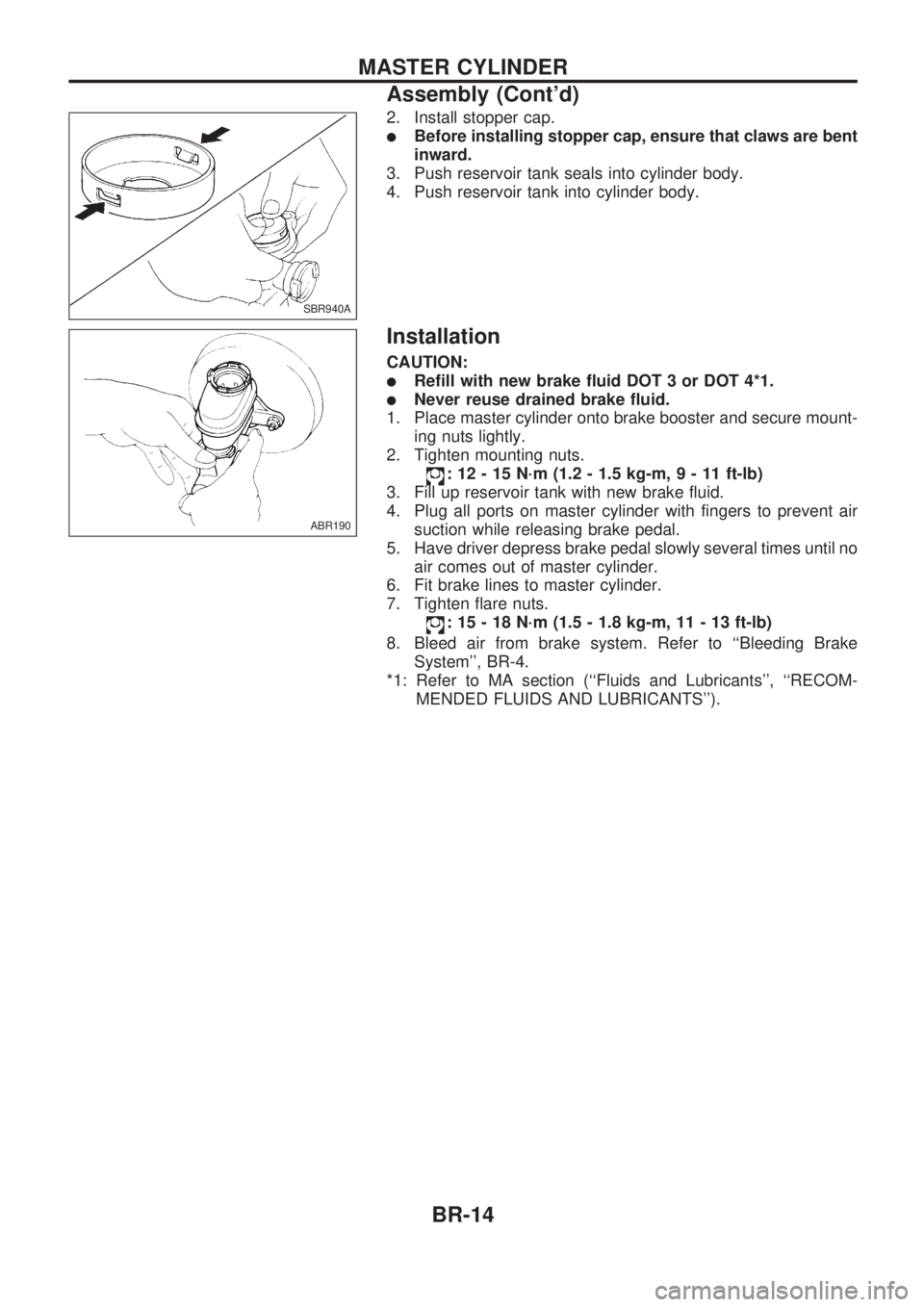
2. Install stopper cap.
lBefore installing stopper cap, ensure that claws are bent
inward.
3. Push reservoir tank seals into cylinder body.
4. Push reservoir tank into cylinder body.
Installation
CAUTION:
lRefill with new brake fluid DOT 3 or DOT 4*1.
lNever reuse drained brake fluid.
1. Place master cylinder onto brake booster and secure mount-
ing nuts lightly.
2. Tighten mounting nuts.
: 12 - 15 N´m (1.2 - 1.5 kg-m,9-11ft-lb)
3. Fill up reservoir tank with new brake fluid.
4. Plug all ports on master cylinder with fingers to prevent air
suction while releasing brake pedal.
5. Have driver depress brake pedal slowly several times until no
air comes out of master cylinder.
6. Fit brake lines to master cylinder.
7. Tighten flare nuts.
: 15 - 18 N´m (1.5 - 1.8 kg-m, 11 - 13 ft-lb)
8. Bleed air from brake system. Refer to ``Bleeding Brake
System'', BR-4.
*1: Refer to MA section (``Fluids and Lubricants'', ``RECOM-
MENDED FLUIDS AND LUBRICANTS'').
SBR940A
ABR190
MASTER CYLINDER
Assembly (Cont'd)
BR-14
Page 20 of 1659

Installation
CAUTION:
lBe careful not to deform or bend brake pipes during
installation of booster.
lReplace clevis pin if damaged.
lRefill with new brake fluid DOT 3 or DOT 4*1.
lNever reuse drained brake fluid.
lTake care not to damage brake booster mounting bolt
thread when installing. Due to the narrow angle of
installation, the threads can be damaged by the dash
panel.
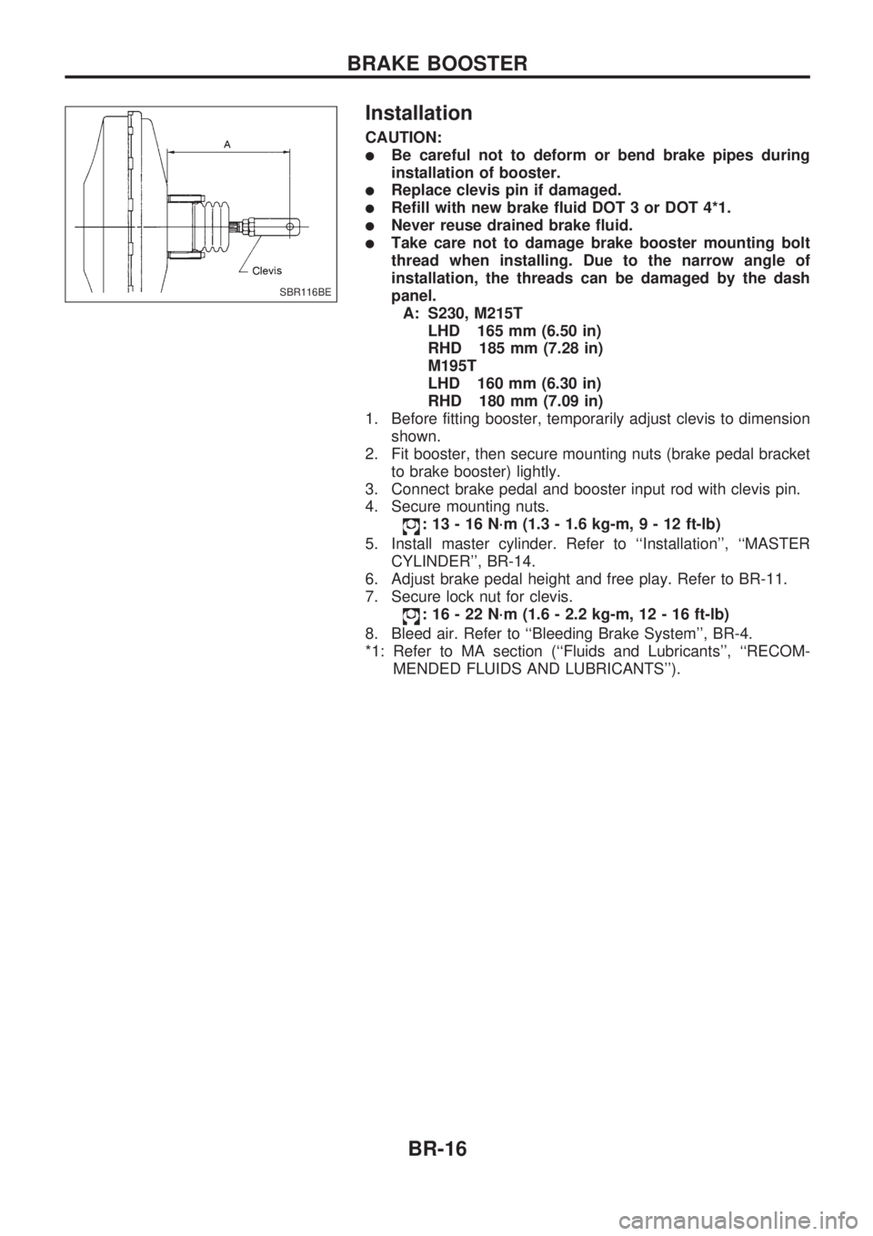
A: S230, M215T
LHD 165 mm (6.50 in)
RHD 185 mm (7.28 in)
M195T
LHD 160 mm (6.30 in)
RHD 180 mm (7.09 in)
1. Before fitting booster, temporarily adjust clevis to dimension
shown.
2. Fit booster, then secure mounting nuts (brake pedal bracket
to brake booster) lightly.
3. Connect brake pedal and booster input rod with clevis pin.
4. Secure mounting nuts.
: 13 - 16 N´m (1.3 - 1.6 kg-m,9-12ft-lb)
5. Install master cylinder. Refer to ``Installation'', ``MASTER
CYLINDER'', BR-14.
6. Adjust brake pedal height and free play. Refer to BR-11.
7. Secure lock nut for clevis.
: 16 - 22 N´m (1.6 - 2.2 kg-m, 12 - 16 ft-lb)
8. Bleed air. Refer to ``Bleeding Brake System'', BR-4.
*1: Refer to MA section (``Fluids and Lubricants'', ``RECOM-
MENDED FLUIDS AND LUBRICANTS'').
SBR116BE
BRAKE BOOSTER
BR-16
Page 28 of 1659

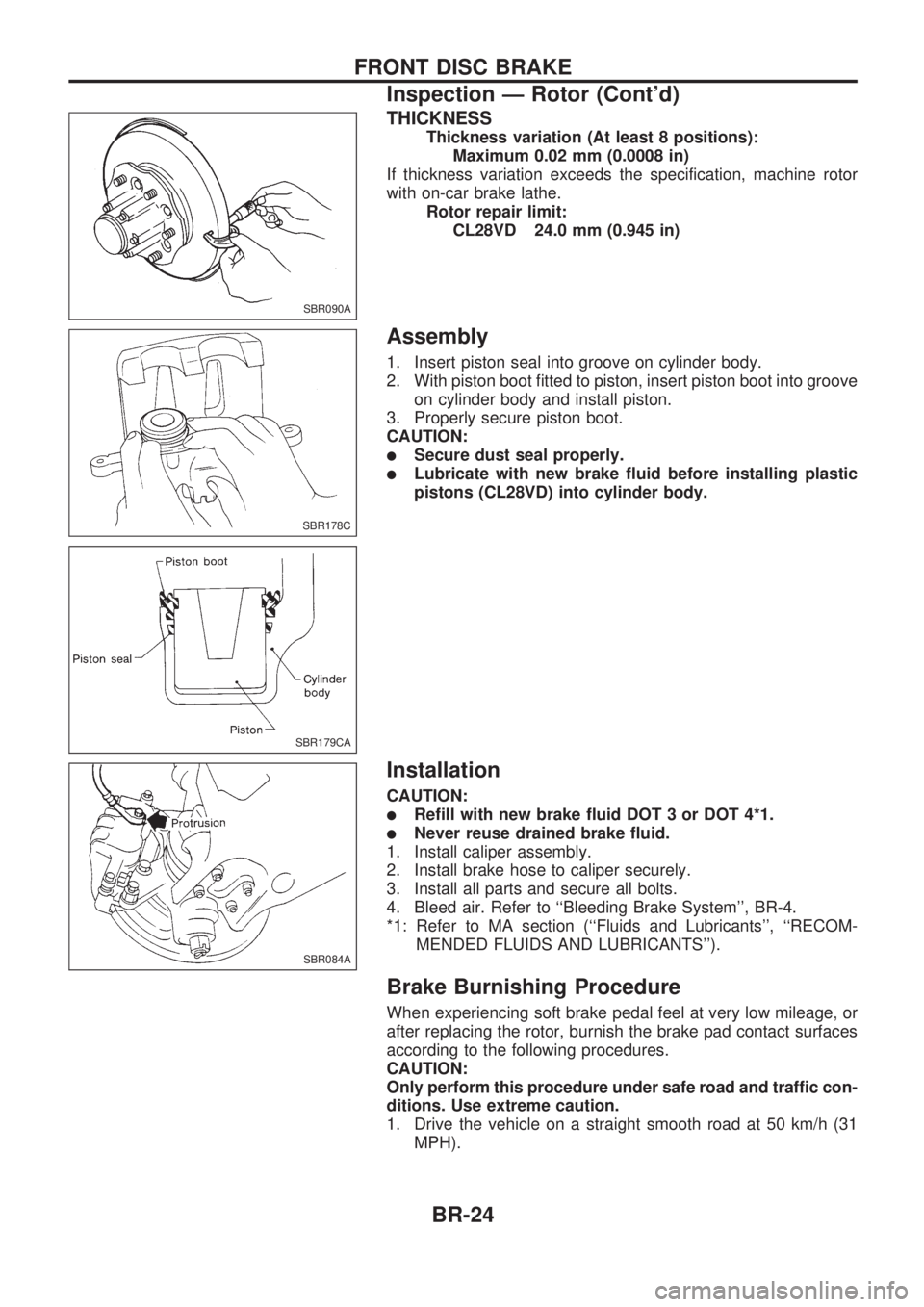
THICKNESS
Thickness variation (At least 8 positions):
Maximum 0.02 mm (0.0008 in)
If thickness variation exceeds the specification, machine rotor
with on-car brake lathe.
Rotor repair limit:
CL28VD 24.0 mm (0.945 in)
Assembly
1. Insert piston seal into groove on cylinder body.
2. With piston boot fitted to piston, insert piston boot into groove
on cylinder body and install piston.
3. Properly secure piston boot.
CAUTION:
lSecure dust seal properly.
lLubricate with new brake fluid before installing plastic
pistons (CL28VD) into cylinder body.
Installation
CAUTION:
lRefill with new brake fluid DOT 3 or DOT 4*1.
lNever reuse drained brake fluid.
1. Install caliper assembly.
2. Install brake hose to caliper securely.
3. Install all parts and secure all bolts.
4. Bleed air. Refer to ``Bleeding Brake System'', BR-4.
*1: Refer to MA section (``Fluids and Lubricants'', ``RECOM-
MENDED FLUIDS AND LUBRICANTS'').
Brake Burnishing Procedure
When experiencing soft brake pedal feel at very low mileage, or
after replacing the rotor, burnish the brake pad contact surfaces
according to the following procedures.
CAUTION:
Only perform this procedure under safe road and traffic con-
ditions. Use extreme caution.
1. Drive the vehicle on a straight smooth road at 50 km/h (31
MPH).
SBR090A
SBR178C
SBR179CA
SBR084A
FRONT DISC BRAKE
Inspection Ð Rotor (Cont'd)
BR-24
Page 60 of 1659

CONSULT
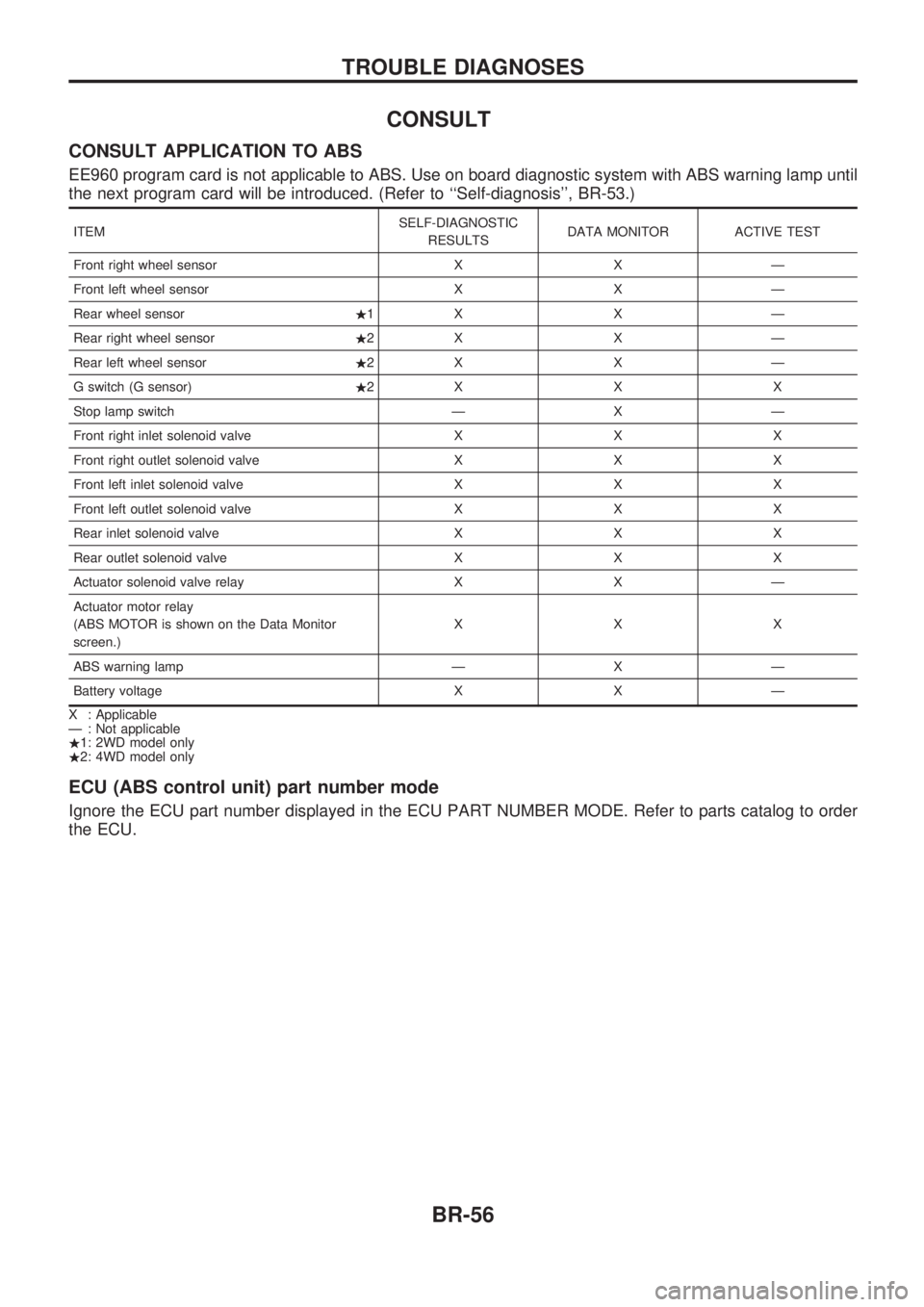
CONSULT APPLICATION TO ABS
EE960 program card is not applicable to ABS. Use on board diagnostic system with ABS warning lamp until
the next program card will be introduced. (Refer to ``Self-diagnosis'', BR-53.)
ITEMSELF-DIAGNOSTIC
RESULTSDATA MONITOR ACTIVE TEST
Front right wheel sensor X X Ð
Front left wheel sensor X X Ð
Rear wheel sensor.1X X Ð
Rear right wheel sensor.2X X Ð
Rear left wheel sensor.2X X Ð
G switch (G sensor).2XXX
Stop lamp switch Ð X Ð
Front right inlet solenoid valve X X X
Front right outlet solenoid valve X X X
Front left inlet solenoid valve X X X
Front left outlet solenoid valve X X X
Rear inlet solenoid valve X X X
Rear outlet solenoid valve X X X
Actuator solenoid valve relay X X Ð
Actuator motor relay
(ABS MOTOR is shown on the Data Monitor
screen.)XXX
ABS warning lamp Ð X Ð
Battery voltage X X Ð
X : Applicable
Ð : Not applicable
.1: 2WD model only
.2: 4WD model only
ECU (ABS control unit) part number mode
Ignore the ECU part number displayed in the ECU PART NUMBER MODE. Refer to parts catalog to order
the ECU.
TROUBLE DIAGNOSES
BR-56
Page 105 of 1659
Body Front End
lWhen removing or installing hood, place a cloth or other padding on hood. This prevents vehicle body
from being scratched.
lBumper fascia is made of plastic. Do not use excessive force and be sure to keep oil away from it.
lHood adjustment: Adjust at hinge portion.
lHood lock adjustment: After adjusting, check hood lock control operation. Apply a coat of grease to hood
locks engaging mechanism.
lHood opener: Do not attempt to bend cable forcibly. Doing so increases effort required to unlock hood.
REMOVAL Ð Front bumper assembly
V1Remove screws securing left and right combination lamps and remove the lamps.
V2Remove clips securing front grille and remove the front grille.
V3Remove bolts securing left and right bumper stays.
V4Remove bolts securing left and right bumper side brackets.
V5Remove bolts securing left and right bumper side stays.
V6Extract bumper assembly.
BODY END
BT-5
Page 108 of 1659
Body Rear End
lAdjustment: Adjust at hinge portion for proper fit.
lLock system adjustment: Adjust striker so that it is in the center of the lock. After adjustment, check trunk
lid lock operation.
lAfter installation, make sure that rear gate opens smoothly.
REMOVAL Ð Rear bumper assembly
V1Remove connectors securing license plate lamps.
V2Remove nuts securing bumper side stay.
V3Extract bumper assembly.
SBT429
BODY END
BT-8
Page 118 of 1659
Door Trim
REMOVAL Ð Door trim
Front door trim
V1Remove inside handle escutcheon.
V2Remove power window switch, then disconnect the connector.
V3Remove window regulator handle.
V4Remove door armrest.
V5Remove screw securing pull handle and remove pull handle.
V6Remove bolt, screw and clip securing door finisher.
V7Lift out door finisher.
Rear door trim
V8Remove inside handle escutcheon.
V9Remove screws securing door handle and remove door handle.
V10Remove clips and lift out door finisher, then disconnect power window switch connector.
INTERIOR TRIM
BT-18
Page 123 of 1659
REMOVE Ð Headlining (King cab model)
V1Remove front seats and jump seats. Refer to ``SEAT'' for details, BT-30, 34.
V2Remove body side trim. Refer to ``Side and Floor Trim'' (King cab model) for details, BT-15.
V3Remove assist grip.
V4Remove roof side garnishes.
V5Remove interior lamp assembly.
V6Remove back window upper garnish.
V7Remove inside mirror assembly.
V8Remove sun visors.
V9Remove windshield upper welt.
V10Remove clips securing headlining.
SBT632
INTERIOR TRIM
Roof Trim (Cont'd)
BT-23