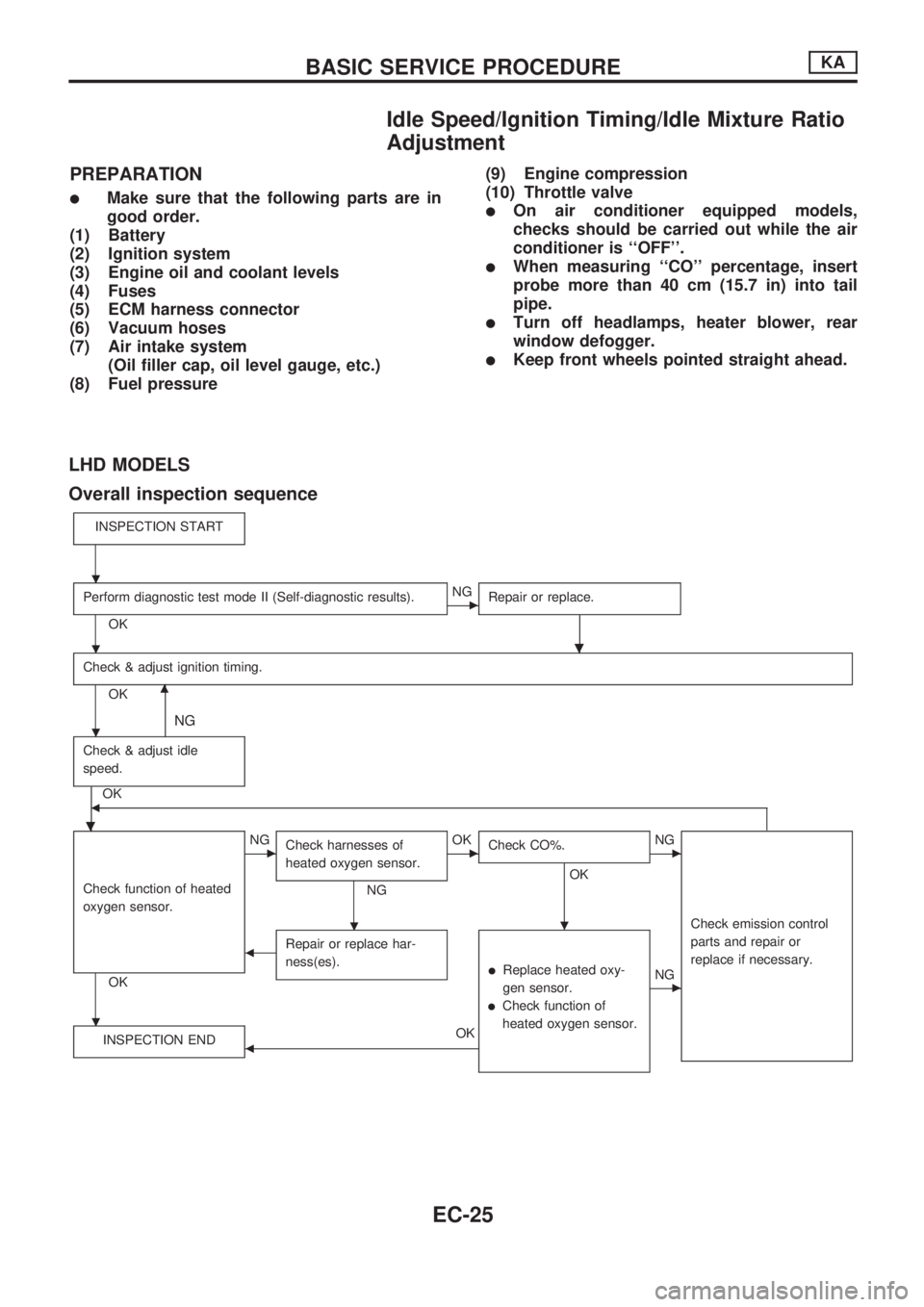
Page 177 of 1659

Idle Speed/Ignition Timing/Idle Mixture Ratio
Adjustment
PREPARATION
lMake sure that the following parts are in
good order.
(1) Battery
(2) Ignition system
(3) Engine oil and coolant levels
(4) Fuses
(5) ECM harness connector
(6) Vacuum hoses
(7) Air intake system
(Oil filler cap, oil level gauge, etc.)
(8) Fuel pressure(9) Engine compression
(10) Throttle valvelOn air conditioner equipped models,
checks should be carried out while the air
conditioner is ``OFF''.
lWhen measuring ``CO'' percentage, insert
probe more than 40 cm (15.7 in) into tail
pipe.
lTurn off headlamps, heater blower, rear
window defogger.
lKeep front wheels pointed straight ahead.
LHD MODELS
Overall inspection sequence
INSPECTION START
Perform diagnostic test mode II (Self-diagnostic results).
OK
cNG
Repair or replace.
.
Check & adjust ignition timing.
OKm
NG
Check & adjust idle
speed.
.
OKb
Check function of heated
oxygen sensor.
OK
cNG
Check harnesses of
heated oxygen sensor.
NG
cOK
Check CO%.
OK
.
cNG
Check emission control
parts and repair or
replace if necessary.
bRepair or replace har-
ness(es).
lReplace heated oxy-
gen sensor.
lCheck function of
heated oxygen sensor.
cNG
INSPECTION END
bOK
.
.
.
.
.
BASIC SERVICE PROCEDUREKA
EC-25
Page 891 of 1659
Symptom Chart
DIAGNOSTIC TABLE
PROCEDUREPreliminary
CheckDiagnostic
ProcedureMain
Power
Supply
and
Ground
Circuit
CheckElectrical Components Inspection
REFERENCE PAGE
HA-21
HA-22
HA-23
HA-37
HA-39
HA-36
HA-43
HA-43
HA-43
HA-43
HA-44
HA-44
HA-44
HA-60
HA-45
Ð
SYMPTOM
Preliminary check 1
Preliminary check 2
Preliminary check 3
Diagnostic procedure 1
Diagnostic procedure 2
15A Fuses (No.
19
and
20 )
7.5A Fuse (No.
21 )
Blower motor
Blower resistor
A/C switch
Fan switch
Thermo control amp.
A/C relay
Triple-pressure switch
Compressor
Harness Magnet clutch
Thermal protector
A/C does not blow cold air.j jjjjjjjjjjjj
Blower motor does not rotate.
jjjjj j
Magnet clutch does not
engage when A/C switch and
fan switch are ON.
j jjjjjjjj
Noise.
Insufficient heating.jj
,: The number means checking order.
j: Checking order depends on malfunction in flow chart.
TROUBLE DIAGNOSES
HA-20
Page 907 of 1659

Main Power Supply and Ground Circuit
Check
POWER SUPPLY FUSE CHECK FOR A/C SYSTEM
Check the following fuses.
l15A fuse (No.19 and20 ) for blower motor.
l7.5A fuse (No.21 ) for thermo control amp.
For detailed circuit, refer to ``Wiring Diagram''.
THERMO CONTROL AMP. CHECK
Power supply circuit check
Check power supply circuit for thermo control amp. with ignition
switch ON.
1. Disconnect thermo control amp. harness connector.
2. Connect voltmeter from harness side.
3. Measure voltage across terminal No.
V1and body ground.
Voltmeter terminal
Voltage
Å@
V1Body ground Approx. 12V
Ground circuit check
Check body ground circuit for thermo control amp. with ignition
switch ON, air conditioner switch ON and fan switch ON.
1. Disconnect thermo control amp. harness connector.
2. Connect ohmmeter from harness side.
3. Check for continuity between terminal No.
V2and body
ground.
Ohmmeter terminal
Continuity
Å@
V2Body ground Yes
If the ground circuit is NG, check the following.
lA/C switch (Refer to HA-43.)
lFan switch (Refer to HA-43.)
lHarness for open or short between thermo control amp. and
A/C switch
lHarness for open or short between A/C switch and fan switch
lFan switch ground circuit
SHA877E
RHA319GA
SHA102F
TROUBLE DIAGNOSES
HA-36
Page 908 of 1659

INCIDENTFlow chart
No.
1 Fan fails to rotate.
2 Fan does not rotate at 1-speed.
3 Fan does not rotate at 2-speed.
4 Fan does not rotate at 3-speed.
5 Fan does not rotate at 4-speed.
Diagnostic Procedure 1
SYMPTOM: Blower motor does not rotate.
lPerform PRELIMINARY CHECK 1 before referring to the
following flow chart.
Check if blower motor rotates properly
at each fan speed.
Conduct checks as per flow chart at
left.
cVE
cVD
cVC
cVB
(Go to next page.)
CHECK POWER SUPPLY FOR BLOWER
MOTOR.
Disconnect blower motor harness connec-
tor.
Do approx. 12 volts exist between blower
motor harness terminal No.
V1and body
ground?
Yes
cNo
Check 15A fuses (No.19
and No.20 , located in
the fuse block).
(Refer to ``POWER SUP-
PLY ROUTING'' in EL sec-
tion and Wiring Diagram.)
1. Turn fan control knob to any position
except OFF.
2. Check circuit continuity between blower
motor harness terminal No.
V2and
body ground.
Continuity should exist.
OK
cNG
Reconnect blower motor
harness connector.
CHECK BLOWER MOTOR.
(Refer to Electrical Components Inspec-
tion.) (HA-43)
NG
Replace blower motor.
.
CHECK BLOWER MOTOR CIRCUIT
BETWEEN BLOWER MOTOR AND
RESISTOR.
Do approx. 12 volts exist between resistor
harness terminal No.
V1and body
ground?
Yes
cNo
Disconnect blower motor
and resistor harness con-
nectors.
Disconnect fan switch harness connector.Note
Check circuit continuity
between blower motor har-
ness terminal No.
V2and
resistor harness terminal
No.
V1.
Continuity should exist.
If OK, check harness for
short.
VA(Go to next page.)
Note:
If the result is NG after checking circuit continuity, repair harness or con-
nector.
SHA872E
SHA873E
RHA320G
RHA321G
.
.
.
.
..
.
TROUBLE DIAGNOSES
HA-37