1998 NISSAN PICK-UP clock
[x] Cancel search: clockPage 193 of 1659
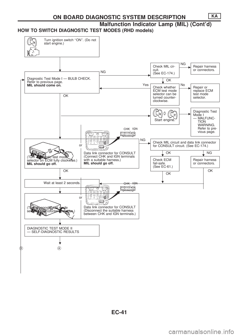
HOW TO SWITCH DIAGNOSTIC TEST MODES (RHD models)
Turn ignition switch ``ON''. (Do not
start engine.)
cDiagnostic Test Mode I Ð BULB CHECK.
Refer to previous page.
MIL should come on.
OK
cNGCheck MIL cir-
cuit.
(See EC-174.)
OK
cNG
Repair harness
or connectors.
bYes
Check whether
ECM test mode
selector can be
turned counter-
clockwise.cNo
Repair or
replace ECM
test mode
selector.
cG
Start engine.
cDiagnostic Test
Mode I
Ð MALFUNC-
TION
WARNING.
Refer to pre-
vious page.
Data link connector for CONSULT
(Connect CHK and IGN terminals
with a suitable harness.)
MIL should go off. (Turn diagnostic test mode
selector on ECM fully clockwise.)
MIL should go off.or
OK
cNG
Check MIL circuit and data link connector
for CONSULT circuit. (See EC-174.)
OK NG
Check ECM
fail-safe.
(See EC-61.)
OKRepair harness
or connectors.OK
Wait at least 2 seconds.
b
Data link connector for CONSULT
(Disconnect the suitable harness
between CHK and IGN terminals.) (Turn diagnostic test mode
selector fully counterclockwise.)or
DIAGNOSTIC TEST MODE II
Ð SELF-DIAGNOSTIC RESULTS
VBVA
.
.
.
..
.
.
.
.
.
ON BOARD DIAGNOSTIC SYSTEM DESCRIPTIONKA
Malfunction Indicator Lamp (MIL) (Cont'd)
EC-41
Page 194 of 1659
VBmVA
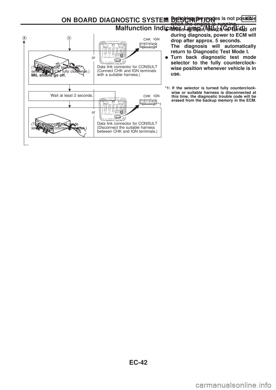
Data link connector for CONSULT
(Connect CHK and IGN terminals
with a suitable harness.) (Turn diagnostic test mode
selector on ECM fully clockwise.)
MIL should go off.or
Wait at least 2 seconds.
*1
Data link connector for CONSULT
(Disconnect the suitable harness
between CHK and IGN terminals.) (Turn diagnostic test mode
selector fully counterclockwise.)or
lSwitching the modes is not possible
when the engine is running.
lWhen ignition switch is turned off
during diagnosis, power to ECM will
drop after approx. 5 seconds.
The diagnosis will automatically
return to Diagnostic Test Mode I.
lTurn back diagnostic test mode
selector to the fully counterclock-
wise position whenever vehicle is in
use.
*1: If the selector is turned fully counterclock-
wise or suitable harness is disconnected at
this time, the diagnostic trouble code will be
erased from the backup memory in the ECM.
.
.
.
ON BOARD DIAGNOSTIC SYSTEM DESCRIPTIONKA
Malfunction Indicator Lamp (MIL) (Cont'd)
EC-42
Page 330 of 1659
Inspection
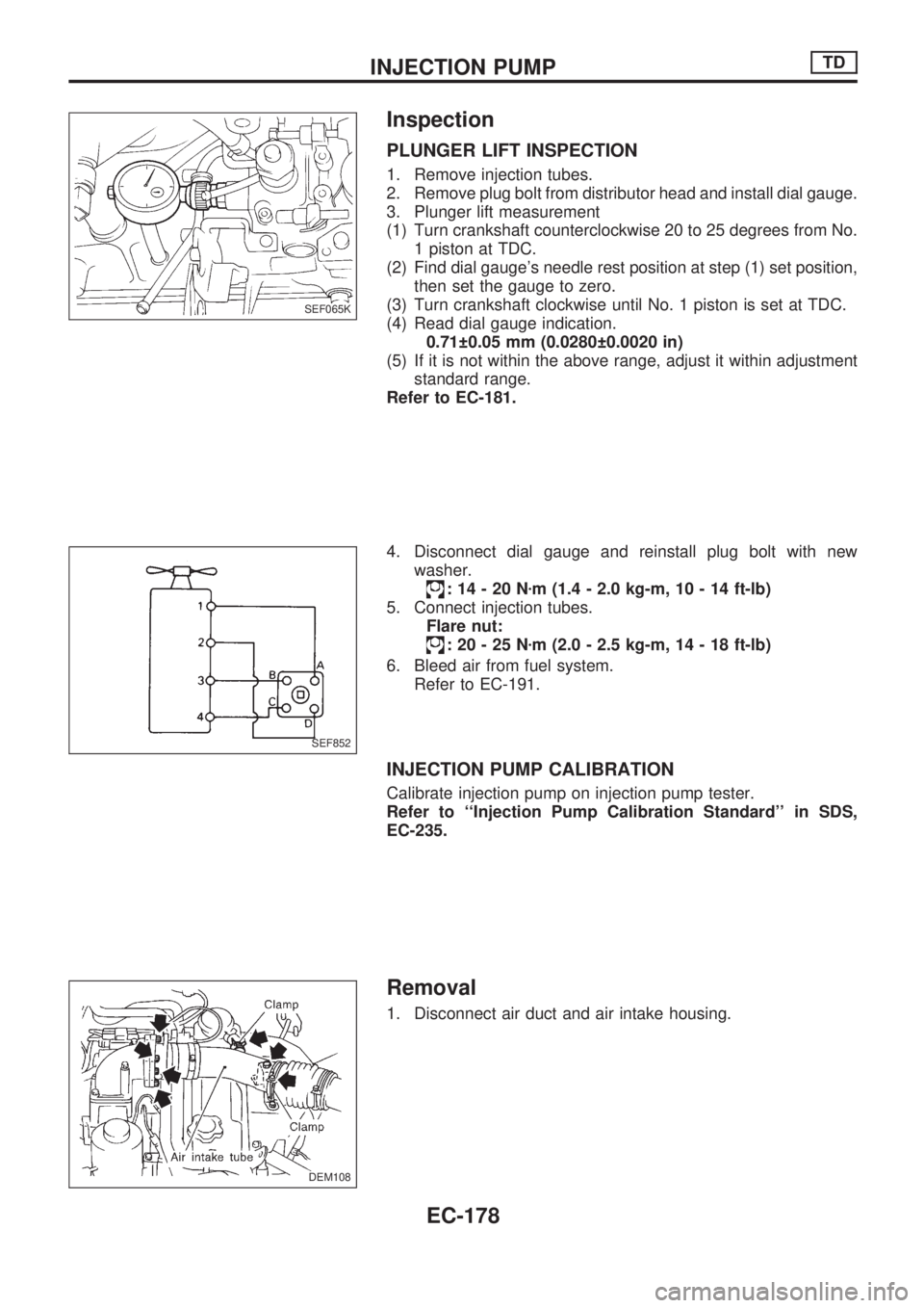
PLUNGER LIFT INSPECTION
1. Remove injection tubes.
2. Remove plug bolt from distributor head and install dial gauge.
3. Plunger lift measurement
(1) Turn crankshaft counterclockwise 20 to 25 degrees from No.
1 piston at TDC.
(2) Find dial gauge's needle rest position at step (1) set position,
then set the gauge to zero.
(3) Turn crankshaft clockwise until No. 1 piston is set at TDC.
(4) Read dial gauge indication.
0.71 0.05 mm (0.0280 0.0020 in)
(5) If it is not within the above range, adjust it within adjustment
standard range.
Refer to EC-181.
4. Disconnect dial gauge and reinstall plug bolt with new
washer.
:14-20Nzm (1.4 - 2.0 kg-m, 10 - 14 ft-lb)
5. Connect injection tubes.
Flare nut:
:20-25Nzm (2.0 - 2.5 kg-m, 14 - 18 ft-lb)
6. Bleed air from fuel system.
Refer to EC-191.
INJECTION PUMP CALIBRATION
Calibrate injection pump on injection pump tester.
Refer to ``Injection Pump Calibration Standard'' in SDS,
EC-235.
Removal
1. Disconnect air duct and air intake housing.
SEF065K
SEF852
DEM108
.
INJECTION PUMPTD
EC-178
Page 333 of 1659
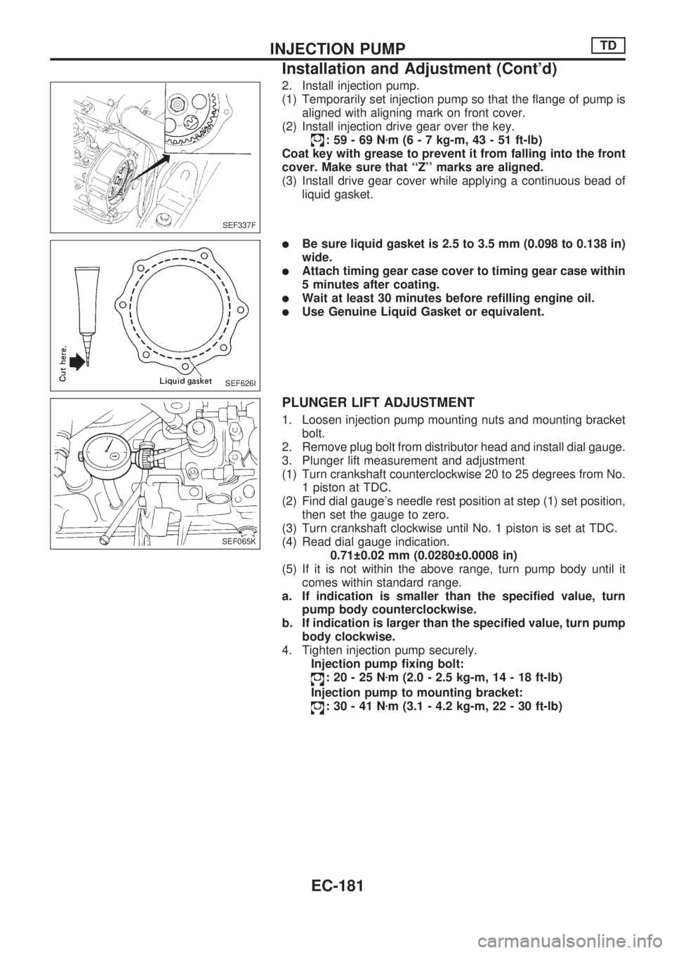
2. Install injection pump.
(1) Temporarily set injection pump so that the flange of pump is
aligned with aligning mark on front cover.
(2) Install injection drive gear over the key.
:59-69Nzm (6 - 7 kg-m, 43 - 51 ft-lb)
Coat key with grease to prevent it from falling into the front
cover. Make sure that ``Z'' marks are aligned.
(3) Install drive gear cover while applying a continuous bead of
liquid gasket.
lBe sure liquid gasket is 2.5 to 3.5 mm (0.098 to 0.138 in)
wide.
lAttach timing gear case cover to timing gear case within
5 minutes after coating.
lWait at least 30 minutes before refilling engine oil.
lUse Genuine Liquid Gasket or equivalent.
PLUNGER LIFT ADJUSTMENT
1. Loosen injection pump mounting nuts and mounting bracket
bolt.
2. Remove plug bolt from distributor head and install dial gauge.
3. Plunger lift measurement and adjustment
(1) Turn crankshaft counterclockwise 20 to 25 degrees from No.
1 piston at TDC.
(2) Find dial gauge's needle rest position at step (1) set position,
then set the gauge to zero.
(3) Turn crankshaft clockwise until No. 1 piston is set at TDC.
(4) Read dial gauge indication.
0.71 0.02 mm (0.0280 0.0008 in)
(5) If it is not within the above range, turn pump body until it
comes within standard range.
a. If indication is smaller than the specified value, turn
pump body counterclockwise.
b. If indication is larger than the specified value, turn pump
body clockwise.
4. Tighten injection pump securely.
Injection pump fixing bolt:
:20-25Nzm (2.0 - 2.5 kg-m, 14 - 18 ft-lb)
Injection pump to mounting bracket:
:30-41Nzm (3.1 - 4.2 kg-m, 22 - 30 ft-lb)
SEF337F
SEF626I
SEF065K
INJECTION PUMPTD
Installation and Adjustment (Cont'd)
EC-181
Page 334 of 1659
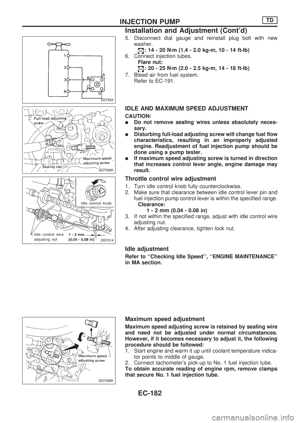
5. Disconnect dial gauge and reinstall plug bolt with new
washer.
:14-20Nzm (1.4 - 2.0 kg-m, 10 - 14 ft-lb)
6. Connect injection tubes.
Flare nut:
:20-25Nzm (2.0 - 2.5 kg-m, 14 - 18 ft-lb)
7. Bleed air from fuel system.
Refer to EC-191.
IDLE AND MAXIMUM SPEED ADJUSTMENT
CAUTION:
lDo not remove sealing wires unless absolutely neces-
sary.
lDisturbing full-load adjusting screw will change fuel flow
characteristics, resulting in an improperly adjusted
engine. Readjustment of fuel injection pump should be
done using a pump tester.
lIf maximum speed adjusting screw is turned in direction
that increases control lever angle, engine damage may
result.
Throttle control wire adjustment
1. Turn idle control knob fully counterclockwise.
2. Make sure that clearance between idle control lever pin and
fuel injection pump control lever is within the specified range.
Clearance:
1-2mm(0.04 - 0.08 in)
3. If not within the specified range, adjust with idle control wire
adjusting nut.
4. After adjusting clearance, tighten lock nut.
Idle adjustment
Refer to ``Checking Idle Speed'', ``ENGINE MAINTENANCE''
in MA section.
Maximum speed adjustment
Maximum speed adjusting screw is retained by sealing wire
and need not be adjusted under normal circumstances.
However, if it becomes necessary to adjust it, the following
procedure should be followed:
1. Start engine and warm it up until coolant temperature indica-
tor points to middle of gauge.
2. Connect tachometer's pick-up to No. 1 fuel injection tube.
To obtain accurate reading of engine rpm, remove clamps
that secure No. 1 fuel injection tube.
SEF852
SEF066K
DEF014
SEF068K
INJECTION PUMPTD
Installation and Adjustment (Cont'd)
EC-182
Page 335 of 1659
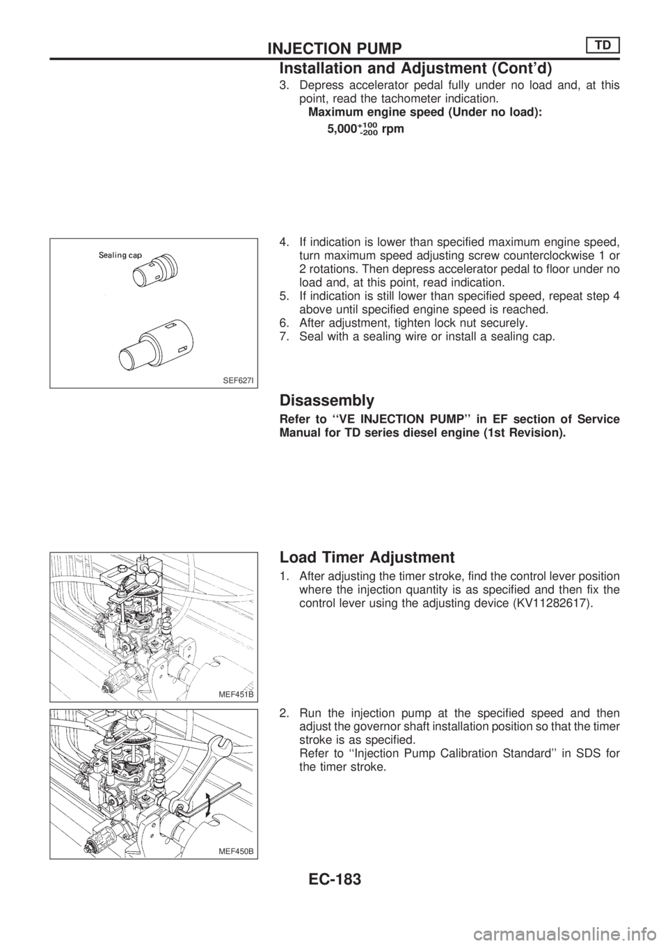
3. Depress accelerator pedal fully under no load and, at this
point, read the tachometer indication.
Maximum engine speed (Under no load):
5,000
+100
-200rpm
4. If indication is lower than specified maximum engine speed,
turn maximum speed adjusting screw counterclockwise 1 or
2 rotations. Then depress accelerator pedal to floor under no
load and, at this point, read indication.
5. If indication is still lower than specified speed, repeat step 4
above until specified engine speed is reached.
6. After adjustment, tighten lock nut securely.
7. Seal with a sealing wire or install a sealing cap.
Disassembly
Refer to ``VE INJECTION PUMP'' in EF section of Service
Manual for TD series diesel engine (1st Revision).
Load Timer Adjustment
1. After adjusting the timer stroke, find the control lever position
where the injection quantity is as specified and then fix the
control lever using the adjusting device (KV11282617).
2. Run the injection pump at the specified speed and then
adjust the governor shaft installation position so that the timer
stroke is as specified.
Refer to ``Injection Pump Calibration Standard'' in SDS for
the timer stroke.
SEF627I
MEF451B
MEF450B
INJECTION PUMPTD
Installation and Adjustment (Cont'd)
EC-183
Page 386 of 1659
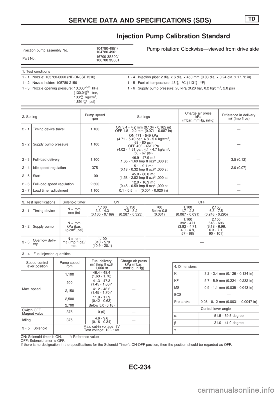
Injection Pump Calibration Standard
Injection pump assembly No.104780-4951/
104780-4961
Part No.16700 3S300/
106700 3S301Pump rotation: ClockwiseÐviewed from drive side
1. Test conditions
1 - 1 Nozzle: 105780-0060 (NP-DN0SD1510) 1 - 4 Injection pipe: 2 dia. x 6 dia. x 450 mm (0.08 dia. x 0.24 dia. x 17.72 in)
1 - 2 Nozzle holder: 105780-2150 1 - 5 Fuel oil temperature: 45
+5
0ÉC (113+9
0ÉF)
1 - 3 Nozzle opening pressure: 13,000+300
0kPa
(130.0+3.0
0bar,
133+3
0kg/cm2,
1,891+43
0psi)1 - 6 Supply pump pressure: 20 kPa (0.20 bar, 0.2 kg/cm
2, 2.8 psi)
2. SettingPump speed
rpmSettingsCharge air press
kPa
(mbar, mmHg, inHg)Difference in delivery
m!(Imp fl oz)
2 - 1 Timing device travel 1,100ON 3.4 - 4.2 mm (0.134 - 0.165 in)
OFF 1.8 - 2.2 mm (0.071 - 0.087 in)
ÐÐ
2 - 2 Supply pump pressure 1,100ON 471 - 549 kPa
(4.71 - 5.49 bar, 4.8 - 5.6 kg/cm
2,
68 - 80 psi)
OFF 402 - 461 kPa
(4.02 - 4.61 bar, 4.1 - 4.7 kg/cm
2,
58 - 67 psi)Ð
2 - 3 Full-load delivery 1,10046.9 - 47.9 m!
(1.65 - 1.69 Imp fl oz)/1,000 st3.5 (0.12)
2 - 4 Idle speed regulation 3755.1 - 9.1 m!
(0.18 - 0.32 Imp fl oz)/1,000 st2.0 (0.07)
2 - 5 Start 10045.0 - 80.0 m!
(1.58 - 2.82 Imp fl oz)/1,000 stÐ
2 - 6 Full-load speed regulation 2,50012.9 - 16.9 m!
(0.45 - 0.59 Imp fl oz)/1,000 stÐ
2 - 7 Load timer adjustment 1,100 0.1 - 0.5 mm (0.004 - 0.020 in) Ð
3. Test specifications Solenoid timer ON OFF
3 - 1 Timing deviceN = rpm
mm (in)1,100
3.3 - 4.3
(0.130 - 0.169)2,150
7.3 - 8.2
(0.287 - 0.323)700
Below 0.8
(0.031)1,100
1.7 - 2.3
(0.067 - 0.091)2,150
6.3 - 7.5
(0.248 - 0.295)
3 - 2 Supply pumpN = rpm
kPa (bar,
kg/cm
2, psi)1,100
392 - 471
(3.92 - 4.71,
4.0 - 4.8,
57 - 68)2,150
618 - 696
(6.18 - 6.96,
6.3 - 7.1,
90 - 101)
3-3Overflow deliv-
eryN = rpm
m!(Imp fl oz)/
min.1,100
310 - 570
(10.9 - 20.1)Ð
3 - 4 Fuel injection quantities
Speed control
lever positionPump speed
rpmFuel delivery
m!(Imp fl oz)/
1,000 stCharge air press
kPa (mbar,
mmHg, inHg)
Max. speed1,10046.4 - 48.4
(1.63 - 1.70)
Ð 50041.3 - 47.3
(1.45 - 1.66)*
2,15041.2 - 48.2
(1.45 - 1.70)*
2,50011.9 - 17.9
(0.42 - 0.63)
2,700 Below 5.0 (0.18)
Switch OFF
Magnet valve375 0 (0) Ð
Idling 3754.6 - 9.6
(0.16 - 0.34)Ð
3 - 5 SolenoidMax. cut-in voltage: 8V
Test voltage: 12 - 14V
ON: Solenoid timer is ON. *: Reference value
OFF: Solenoid timer is OFF.
If there is no designation in the specifications for the Solenoid Timer's ON-OFF position, then the position should be regarded as OFF.
4. Dimensions
K 3.2 - 3.4 mm (0.126 - 0.134 in)
KF 5.7 - 5.9 mm (0.224 - 0.232 in)
MS 0.9 - 1.1 mm (0.035 - 0.043 in)
BCS Ð
Pre-stroke 0.08 - 0.12 mm (0.0031 - 0.0047 in)
Control lever angle
a51.5 - 59.5 degree
b31.0 - 41.0 degree
gÐ
SERVICE DATA AND SPECIFICATIONS (SDS)TD
EC-234
Page 389 of 1659
HEADLAMP - Headlamp Aiming Control -........... 63
System Description .............................................. 63
Wiring Diagram - H/AIM - .................................... 64
PARKING, LICENSE AND TAIL LAMPS............... 66
Wiring Diagram - TAIL/L -/Except for LHD
Models for Europe ............................................... 66
Wiring Diagram - TAIL/L -/LHD Models for
Europe.................................................................. 68
STOP LAMP............................................................ 70
Wiring Diagram - STOP/L - ................................. 70
BACK-UP LAMP...................................................... 71
Wiring Diagram - BACK/L - ................................. 71
REAR FOG LAMP................................................... 72
Wiring Diagram - R/FOG -/LHD Models .............. 72
Wiring Diagram - R/FOG -/RHD Models ............. 73
TURN SIGNAL AND HAZARD WARNING
LAMPS..................................................................... 74
Schematic ............................................................ 74
Wiring Diagram - TURN -/Except 4WD Models
for Europe ............................................................ 75
Wiring Diagram - TURN -/4WD Models for
Europe.................................................................. 77
Trouble Diagnoses ............................................... 80
Combination Flasher Unit Check ......................... 80
ILLUMINATION........................................................ 81
Wiring Diagram - ILL -/LHD Models .................... 81
Wiring Diagram - ILL -/RHD Models.................... 83
INTERIOR AND SPOT LAMPS............................... 85
Wiring Diagram - INT/L - ..................................... 85
Combination Meter............................................... 87
Schematic ............................................................ 89
Wiring Diagram - METER -/LHD Models............. 90
Wiring Diagram - METER -/RHD Models ............ 93
Unified Control Meter System Description .......... 96
Meter/gauge Operation and Odo/Trip Meter
Segment Check in Diagnosis Mode .................... 96
Flexible Print Circuit (FPC) .................................. 97
Trouble Diagnoses ............................................... 98
Electrical Components Inspection ..................... 103
WARNING LAMPS................................................ 105
Schematic .......................................................... 105
Wiring Diagram - WARN -/LHD Models ............ 106
Wiring Diagram - WARN -/RHD Models............ 111
Electrical Components Inspection ..................... 116
WARNING BUZZER.............................................. 117
Wiring diagram - BUZZER -/LHD Models for
Europe................................................................ 117
Wiring diagram - BUZZER -/RHD Models for
Europe................................................................ 118
Electrical Components Inspection ..................... 119
FRONT WIPER AND WASHER............................ 120
System Description ............................................ 120
Wiring Diagram - WIPER -/LHD Models with
Intermittent ......................................................... 122Wiring Diagram - WIPER -/RHD Models with
Intermittent ......................................................... 124
Trouble Diagnoses ............................................. 126
Wiper Installation and Adjustment ..................... 127
Washer Nozzle Adjustment ............................... 128
Washer Tube Layout ......................................... 128
Wiper Linkage .................................................... 129
HEADLAMP WASHER.......................................... 130
Wiring Diagram - HLC - ..................................... 130
Trouble Diagnoses ............................................. 131
Washer Tube Layout ......................................... 131
Check Valve ....................................................... 131
HORN..................................................................... 132
Wiring Diagram - HORN -.................................. 132
CIGARETTE LIGHTER.......................................... 133
Wiring Diagram - CIGAR - ................................. 133
CLOCK................................................................... 134
Wiring Diagram - CLOCK - ................................ 134
REAR WINDOW DEFOGGER............................... 135
Wiring Diagram - DEF - ..................................... 135
Electrical Components Inspection ..................... 136
Filament Check .................................................. 136
Filament Repair.................................................. 137
AUDIO.................................................................... 138
Wiring Diagram - AUDIO -/LHD Models Type-
2 ......................................................................... 138
Wiring Diagram - AUDIO -/LHD Models Type-
3 ......................................................................... 139
Wiring Diagram - AUDIO -/RHD Models ........... 141
Trouble Diagnoses ............................................. 142
CATS (Code) System/For Europe RHD ............ 143
NATS Audio Link/For Europe LHD (KA24E) ..... 144
AUDIO ANTENNA................................................. 146
Manual Antenna ................................................. 146
Power Antenna/Wiring Diagram - P/ANT - ........ 147
Power Antenna .................................................. 148
POWER DOOR MIRROR...................................... 150
Wiring Diagram - MIRROR -.............................. 150
HEATED SEAT...................................................... 152
Wiring Diagram - H/SEAT - ............................... 152
POWER WINDOW................................................. 154
System Description ............................................ 154
Schematic .......................................................... 156
Wiring Diagram - WINDOW -/LHD Models ....... 157
Wiring Diagram - WINDOW -/RHD Models ....... 161
Trouble Diagnoses ............................................. 165
POWER DOOR LOCK........................................... 166
System Description ............................................ 166
Wiring Diagram - D/LOCK - ............................... 167
Trouble Diagnosis .............................................. 169
MULTI-REMOTE CONTROL SYSTEM/FOR
EUROPE................................................................ 173
System Description ............................................ 173
Schematic .......................................................... 174