1998 NISSAN PICK-UP clock
[x] Cancel search: clockPage 864 of 1659
A
A/C HFC134a (R134a) system precaution .....HA-2
A/C HFC134a (R134a) system service
procedure ................................................. HA-48
A/C HFC134a (R134a) system service
tools............................................................ HA-8
A/C HFC134a system service
equipment precaution .............................. HA-10
A/C air flow .................................................. HA-14
A/C component layout ................................. HA-13
A/C compressor clutch removal and
installation ................................................ HA-60
A/C compressor precaution ........................... HA-6
A/C compressor special service tool ............. HA-6
A/C control linkage adjustment
(manual A/C) ............................................ HA-45
A/C control operation (manual A/C) ............ HA-16
A/C diagnostic work flow
(manual A/C) ............................................ HA-17
A/C lubricant (R134a) .................................. HA-50
A/C operational check ................................. HA-18
A/C performance chart ................................ HA-26
A/C performance test diagnoses ................. HA-24
A/C relay ...................................................... HA-44
A/C switch.............................................. HA-16, 43
A/C symptom chart (manual A/C) ............... HA-20
A/C trouble diagnoses (manual A/C)........... HA-17
AAC/V - Wiring diagram ............................ EC-133
ABS (anti-lock brake system) ...................... BR-32
ABS - Wiring diagram .................................. BR-42
Accelerator control system............................. FE-1
Accelerator wire adjustment........................... FE-2
Air bag disposal ........................................... RS-14
Air bag precautions ......................................... GI-1
Air bag ........................................................... RS-6
Air bleeding (hydraulic clutch)........................ CL-5
Air bleeding for brake system........................ BR-4
Air cleaner filter replacement
(KA24 engine).......................................... MA-19
Air cleaner filter replacement
(TD25 engine).......................................... MA-29
Air conditioner cut control ............................ EC-18
Air flow meter - See Mass air flow
sensor ...................................................... EC-89
Alternator ...................................................... EL-41
Angular tightening application ....................... EM-1
Antenna ...................................................... EL-146
Anti-lock brake system - Wiring
diagram .................................................... BR-42
Audio and A/C control removal and
installation - See Instrument panel .......... BT-12
Auto-lock free-running hub........................... FA-15
Auxiliary air control (AAC) valve................ EC-131
Axle housing (rear) ........................................ RA-5
B
Back window .................................................BT-24Back-up lamp switch (M/T)............................ MT-9
Ball joint front axle ....................................... FA-34
Battery .......................................................... EL-18
Baulk ring (M/T) (FS5R30A)........................ MT-36
Baulk ring (M/T) (FS5W71C)....................... MT-15
Blower motor................................................ HA-43
Blower resistor ............................................. HA-43
Body alignment ............................................ BT-43
Body mounting ............................................. BT-41
Boring/horning cylinder block ...................... EM-41
Brake booster .............................................. BR-15
Brake fluid change ......................................... BR-3
Brake fluid level and line check..................... BR-3
Brake fluid level ........................................... MA-35
Brake hydraulic line ....................................... BR-5
Brake inspection .......................................... MA-36
Brake lines and cables inspection .............. MA-35
Brake lining wear temporary checking ........ MA-37
Brake master cylinder .................................. BR-12
Brake pedal.................................................. BR-10
Bulb specifications...................................... EL-252
Bumper, front ................................................. BT-5
Bumper, rear .................................................. BT-8
C
CHARGE - Wiring diagram ...........................EL-34
CIGAR - Wiring diagram ............................ EL-133
CLOCK - Wiring diagram ........................... EL-134
CMPS - Wiring diagram............................... EC-85
CONSULT for ECCS ................................... EC-45
CONSULT general information ..................... GI-34
Cab body ...................................................... BT-40
Camshaft inspection (KA24 engine) ........... EM-28
Camshaft inspection (TD25 engine) ........... EM-85
Camshaft position sensor (CMPS) .............. EC-82
Canister - See EVAP canister ..................... EC-19
Center bearing assembly
(propeller shaft) ........................................ PD-10
Center bearing disassembly
(propeller shaft) .......................................... PD-9
Center case (Transfer) ................................... TF-8
Charging system .......................................... EL-34
Chassis and body maintenance .................. MA-32
Cigarette lighter .......................................... EL-133
Circuit breaker .............................................. EL-13
Clock........................................................... EL-134
Clutch cover ................................................. CL-13
Clutch disc.................................................... CL-12
Clutch fluid level .......................................... MA-32
Clutch master cylinder ................................... CL-6
Clutch operating cylinder ............................... CL-8
Clutch pedal ................................................... CL-4
Clutch release bearing ................................... CL-9
Clutch release mechanism............................. CL-9
Clutch withdrawal lever .................................. CL-9
Collision diagnosis (2WD models)............... RS-21
Collision diagnosis (4WD models)............... RS-42
ALPHABETICAL INDEX
IDX-2
Page 882 of 1659
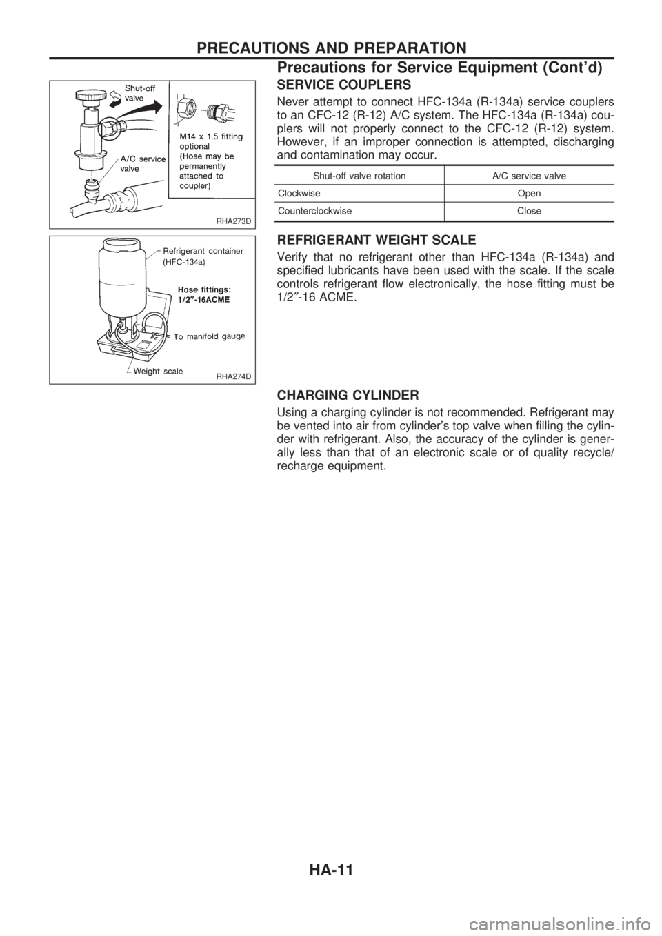
SERVICE COUPLERS
Never attempt to connect HFC-134a (R-134a) service couplers
to an CFC-12 (R-12) A/C system. The HFC-134a (R-134a) cou-
plers will not properly connect to the CFC-12 (R-12) system.
However, if an improper connection is attempted, discharging
and contamination may occur.
Shut-off valve rotation A/C service valve
Clockwise Open
Counterclockwise Close
REFRIGERANT WEIGHT SCALE
Verify that no refrigerant other than HFC-134a (R-134a) and
specified lubricants have been used with the scale. If the scale
controls refrigerant flow electronically, the hose fitting must be
1/2²-16 ACME.
CHARGING CYLINDER
Using a charging cylinder is not recommended. Refrigerant may
be vented into air from cylinder's top valve when filling the cylin-
der with refrigerant. Also, the accuracy of the cylinder is gener-
ally less than that of an electronic scale or of quality recycle/
recharge equipment.
RHA273D
RHA274D
PRECAUTIONS AND PREPARATION
Precautions for Service Equipment (Cont'd)
HA-11
Page 931 of 1659
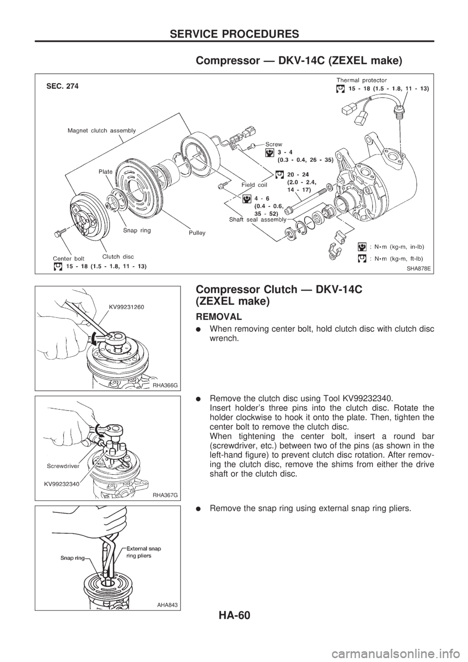
Compressor Ð DKV-14C (ZEXEL make)
Compressor Clutch Ð DKV-14C
(ZEXEL make)
REMOVAL
lWhen removing center bolt, hold clutch disc with clutch disc
wrench.
lRemove the clutch disc using Tool KV99232340.
Insert holder's three pins into the clutch disc. Rotate the
holder clockwise to hook it onto the plate. Then, tighten the
center bolt to remove the clutch disc.
When tightening the center bolt, insert a round bar
(screwdriver, etc.) between two of the pins (as shown in the
left-hand figure) to prevent clutch disc rotation. After remov-
ing the clutch disc, remove the shims from either the drive
shaft or the clutch disc.
lRemove the snap ring using external snap ring pliers.
SHA878E
RHA366G
RHA367G
AHA843
SERVICE PROCEDURES
HA-60
Page 935 of 1659
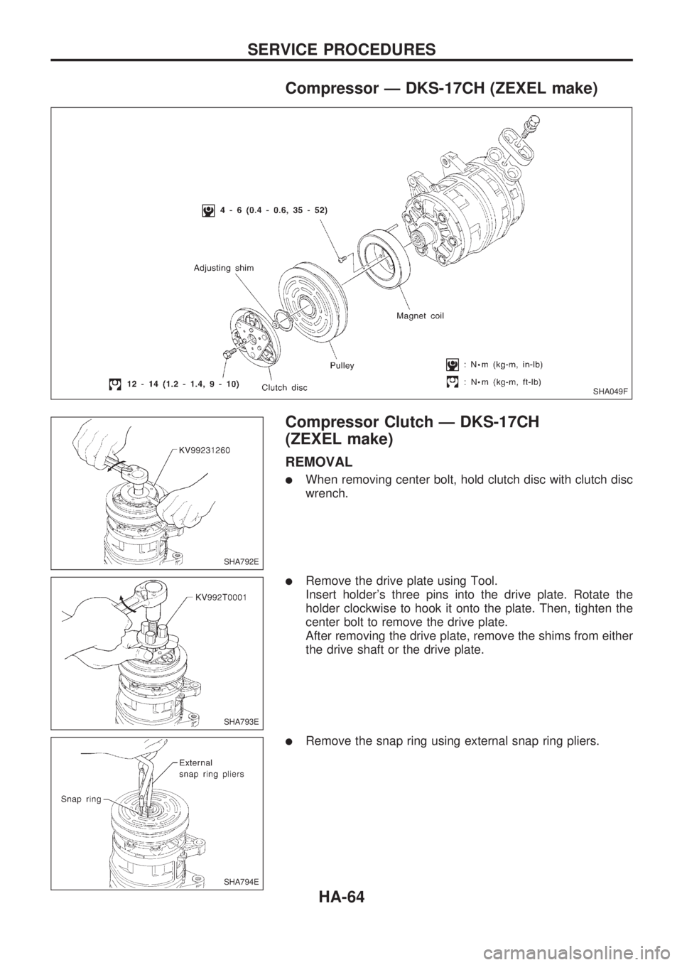
Compressor Ð DKS-17CH (ZEXEL make)
Compressor Clutch Ð DKS-17CH
(ZEXEL make)
REMOVAL
lWhen removing center bolt, hold clutch disc with clutch disc
wrench.
lRemove the drive plate using Tool.
Insert holder's three pins into the drive plate. Rotate the
holder clockwise to hook it onto the plate. Then, tighten the
center bolt to remove the drive plate.
After removing the drive plate, remove the shims from either
the drive shaft or the drive plate.
lRemove the snap ring using external snap ring pliers.
SHA049F
SHA792E
SHA793E
SHA794E
SERVICE PROCEDURES
HA-64
Page 938 of 1659
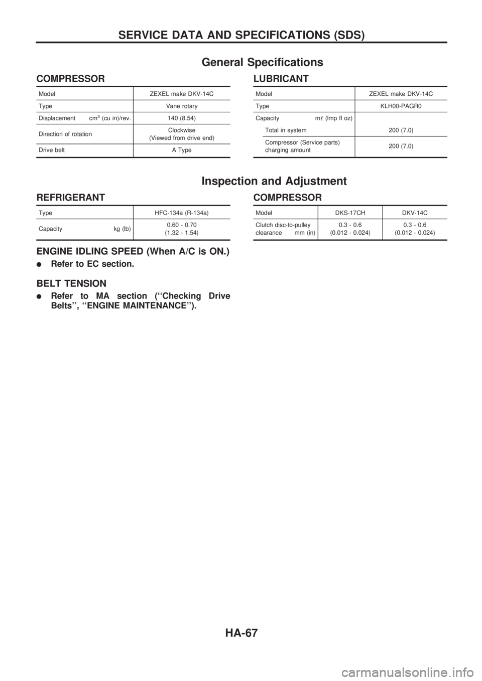
General Specifications
COMPRESSOR
Model ZEXEL make DKV-14C
Type Vane rotary
Displacement cm
3(cu in)/rev. 140 (8.54)
Direction of rotationClockwise
(Viewed from drive end)
Drive belt A Type
LUBRICANT
Model ZEXEL make DKV-14C
Type KLH00-PAGR0
Capacity m!(lmp fl oz)
Total in system 200 (7.0)
Compressor (Service parts)
charging amount200 (7.0)
Inspection and Adjustment
REFRIGERANT
Type HFC-134a (R-134a)
Capacity kg (lb)0.60 - 0.70
(1.32 - 1.54)
ENGINE IDLING SPEED (When A/C is ON.)
lRefer to EC section.
BELT TENSION
lRefer to MA section (``Checking Drive
Belts'', ``ENGINE MAINTENANCE'').
COMPRESSOR
Model DKS-17CH DKV-14C
Clutch disc-to-pulley
clearance mm (in)0.3 - 0.6
(0.012 - 0.024)0.3 - 0.6
(0.012 - 0.024)
SERVICE DATA AND SPECIFICATIONS (SDS)
HA-67
Page 976 of 1659
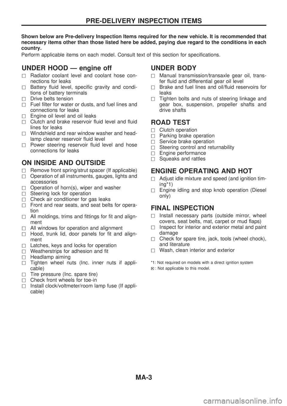
Shown below are Pre-delivery Inspection Items required for the new vehicle. It is recommended that
necessary items other than those listed here be added, paying due regard to the conditions in each
country.
Perform applicable items on each model. Consult text of this section for specifications.
UNDER HOOD Ð engine off
hRadiator coolant level and coolant hose con-
nections for leaks
hBattery fluid level, specific gravity and condi-
tions of battery terminals
hDrive belts tension
hFuel filter for water or dusts, and fuel lines and
connections for leaks
hEngine oil level and oil leaks
hClutch and brake reservoir fluid level and fluid
lines for leaks
hWindshield and rear window washer and head-
lamp cleaner reservoir fluid level
hPower steering reservoir fluid level and hose
connections for leaks
ON INSIDE AND OUTSIDE
hRemove front spring/strut spacer (If applicable)
hOperation of all instruments, gauges, lights and
accessories
hOperation of horn(s), wiper and washer
hSteering lock for operation
hCheck air conditioner for gas leaks
hFront and rear seats, and seat belts for opera-
tion
hAll moldings, trims and fittings for fit and align-
ment
hAll windows for operation and alignment
hHood, trunk lid, door panels for fit and align-
ment
hLatches, keys and locks for operation
hWeatherstrips for adhesion and fit
hHeadlamp aiming
hTighten wheel nuts (Inc. inner nuts if appli-
cable)
hTire pressure (Inc. spare tire)
hCheck front wheels for toe-in
hInstall clock/voltmeter/room lamp fuse (If appli-
cable)
UNDER BODY
hManual transmission/transaxle gear oil, trans-
fer fluid and differential gear oil level
hBrake and fuel lines and oil/fluid reservoirs for
leaks
hTighten bolts and nuts of steering linkage and
gear box, suspension, propeller shafts and
drive shafts
ROAD TEST
hClutch operation
hParking brake operation
hService brake operation
hSteering control and returnability
hEngine performance
hSqueaks and rattles
ENGINE OPERATING AND HOT
hAdjust idle mixture and speed (and ignition tim-
ing*1)
hEngine idling and stop knob operation (Diesel
only)
FINAL INSPECTION
hInstall necessary parts (outside mirror, wheel
covers, seat belts, mat, carpet or mud flaps)
hInspect for interior and exterior metal and paint
damage
hCheck for spare tire, jack, tools (wheel chock),
and literature
hWash, clean interior and exterior
*1: Not required on models with a direct ignition system
h
X: Not applicable to this model.
PRE-DELIVERY INSPECTION ITEMS
MA-3
Page 995 of 1659
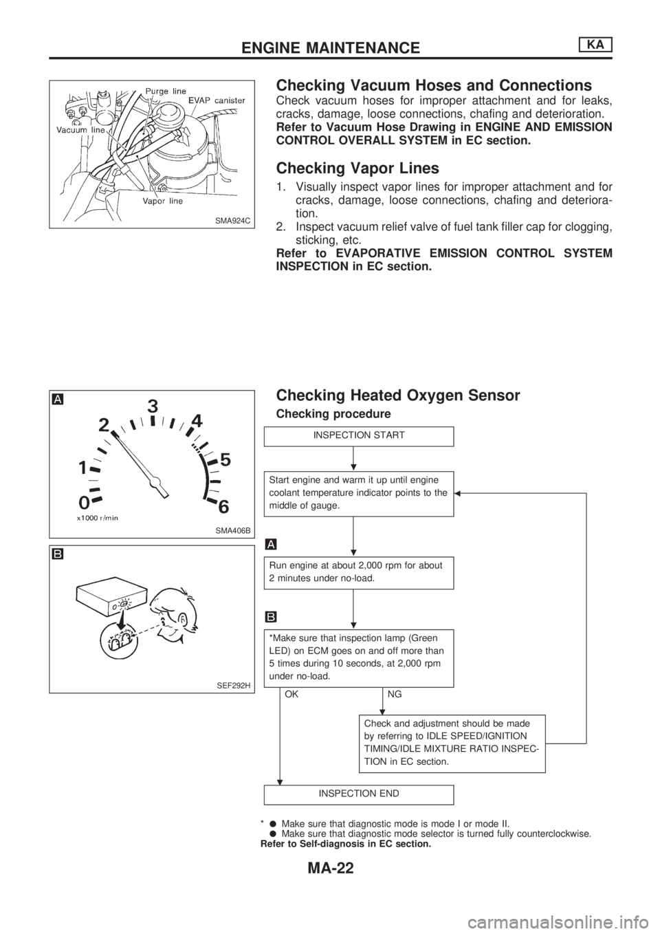
Checking Vacuum Hoses and Connections
Check vacuum hoses for improper attachment and for leaks,
cracks, damage, loose connections, chafing and deterioration.
Refer to Vacuum Hose Drawing in ENGINE AND EMISSION
CONTROL OVERALL SYSTEM in EC section.
Checking Vapor Lines
1. Visually inspect vapor lines for improper attachment and for
cracks, damage, loose connections, chafing and deteriora-
tion.
2. Inspect vacuum relief valve of fuel tank filler cap for clogging,
sticking, etc.
Refer to EVAPORATIVE EMISSION CONTROL SYSTEM
INSPECTION in EC section.
Checking Heated Oxygen Sensor
Checking procedure
INSPECTION START
Start engine and warm it up until engine
coolant temperature indicator points to the
middle of gauge.
b
Run engine at about 2,000 rpm for about
2 minutes under no-load.
*Make sure that inspection lamp (Green
LED) on ECM goes on and off more than
5 times during 10 seconds, at 2,000 rpm
under no-load.
OK NG
.
.
Check and adjustment should be made
by referring to IDLE SPEED/IGNITION
TIMING/IDLE MIXTURE RATIO INSPEC-
TION in EC section.
INSPECTION END
*lMake sure that diagnostic mode is mode I or mode II.lMake sure that diagnostic mode selector is turned fully counterclockwise.
Refer to Self-diagnosis in EC section.
SMA924C
SMA406B
SEF292H
.
.
.
ENGINE MAINTENANCEKA
MA-22
Page 1237 of 1659
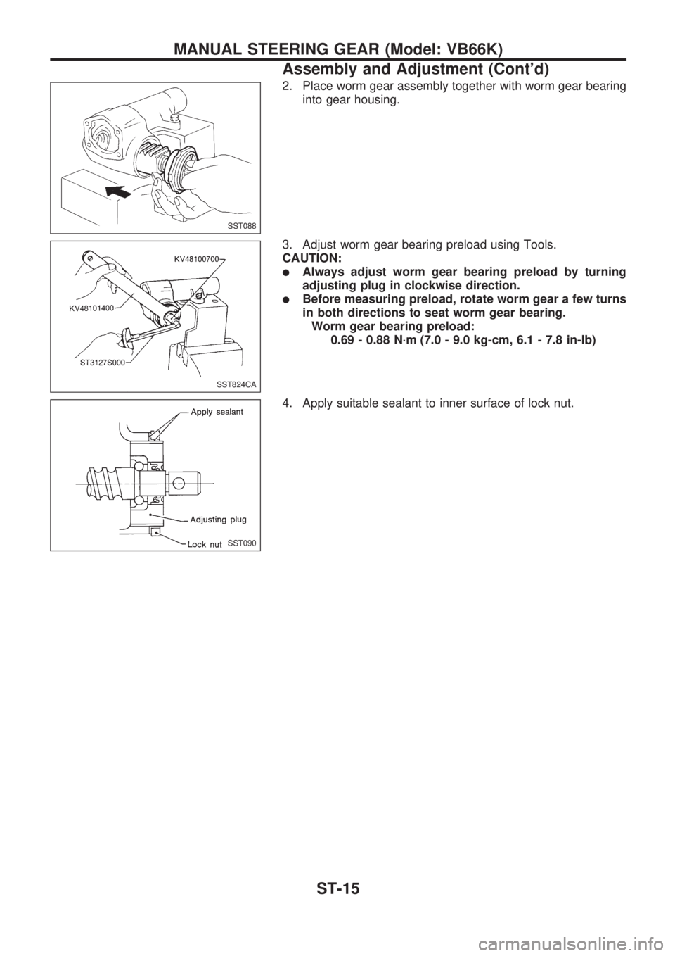
2. Place worm gear assembly together with worm gear bearing
into gear housing.
3. Adjust worm gear bearing preload using Tools.
CAUTION:
lAlways adjust worm gear bearing preload by turning
adjusting plug in clockwise direction.
lBefore measuring preload, rotate worm gear a few turns
in both directions to seat worm gear bearing.
Worm gear bearing preload:
0.69 - 0.88 N´m (7.0 - 9.0 kg-cm, 6.1 - 7.8 in-lb)
4. Apply suitable sealant to inner surface of lock nut.
SST088
SST824CA
SST090
MANUAL STEERING GEAR (Model: VB66K)
Assembly and Adjustment (Cont'd)
ST-15