1998 NISSAN PICK-UP tow bar
[x] Cancel search: tow barPage 172 of 1659

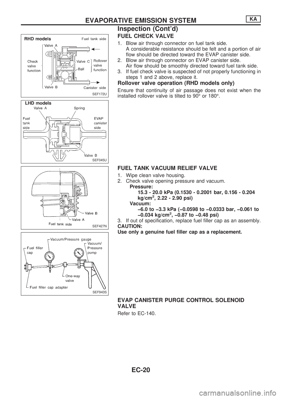
FUEL CHECK VALVE
1. Blow air through connector on fuel tank side.
A considerable resistance should be felt and a portion of air
flow should be directed toward the EVAP canister side.
2. Blow air through connector on EVAP canister side.
Air flow should be smoothly directed toward fuel tank side.
3. If fuel check valve is suspected of not properly functioning in
steps 1 and 2 above, replace it.
Rollover valve operation (RHD models only)
Ensure that continuity of air passage does not exist when the
installed rollover valve is tilted to 90É or 180É.
FUEL TANK VACUUM RELIEF VALVE
1. Wipe clean valve housing.
2. Check valve opening pressure and vacuum.
Pressure:
15.3 - 20.0 kPa (0.1530 - 0.2001 bar, 0.156 - 0.204
kg/cm
2, 2.22 - 2.90 psi)
Vacuum:
þ6.0 to þ3.3 kPa (þ0.0598 to þ0.0333 bar, þ0.061 to
þ0.034 kg/cm
2, þ0.87 to þ0.48 psi)
3. If out of specification, replace fuel filler cap as an assembly.
CAUTION:
Use only a genuine fuel filler cap as a replacement.
EVAP CANISTER PURGE CONTROL SOLENOID
VALVE
Refer to EC-140.
SEF172U
SEF045U
SEF427N
SEF943S
EVAPORATIVE EMISSION SYSTEMKA
Inspection (Cont'd)
EC-20
Page 727 of 1659

REPLACING CAMSHAFT BUSHING
1. Using Tool, remove camshaft bushings from the engine.
Some bushings must be broken in order to remove.
2. Using Tool, install camshaft bushings as follows:
(1) Install camshaft bushings in the order of ``rear'', ``4th'', ``3rd'',
``2nd'' and ``front''. All bushings must be installed from the
front.
(2) Face the cutout upward and toward the front of the engine
during installation.
(3) Rear camshaft bushing
lAlign the cutout of rear bushing with knock pin of replacer bar
before installation.
lInsert rear bushing with replacer bar into the engine.
Install guide plate with bolt holes (on the ``TD'' mark side)
facing upper side of cylinder block. Tighten bolts.
SEM106C
SEM993B
SEM686B
SEM995B
SEM110C
ENGINE OVERHAULTD
Inspection and Replacement (Cont'd)
EM-82
Page 870 of 1659

Throttle body ................................................. EM-9
Throttle position sensor (TPS)................... EC-113
Throwout bearing - See Clutch release
bearing........................................................ CL-9
Tie-rod .......................................................... ST-37
Tie-rod ball joints.......................................... ST-37
Tightening torque of standard bolts .............. GI-54
Timing chain ................................................ EM-13
Timing gear ................................................. EM-89
Tire rotation ................................................. MA-35
Tire size ........................................................ GI-46
Tooth contact (R180A) ................................ PD-26
Tooth contact (C200) ................................... PD-49
Tooth contact (H233B) ................................ PD-70
Torsion bar spring ........................................ FA-28
Tow truck towing ........................................... GI-51
Towing point.................................................. GI-53
Transfer case ................................................. TF-8
Transfer oil replacement ............................. MA-33
Transfer serial number.................................. GI-43
Transmission case (M/T) (FS5R30A).......... MT-35
Transmission case (M/T) (FS5W71C)......... MT-14
Transmission serial number.......................... GI-43
Tread - FR&RR (Dimensions) ...................... GI-44
Trim .............................................................. BT-15
Triple pressure switch ........................... HA-12, 44
Turn signal lamp........................................... EL-74
Two-pole lift................................................... GI-50
U
Under body ....................................................BT-46
Upper link (front susp.) ................................ FA-31
V
VSS - Wiring diagram .................................EC-119
Vacuum hose (brake system) .......................BR-17
Vacuum hose drawing (ECCS).....................EC-12
Vacuum pump ...............................................BR-19
Valve clearance adjustment .........................MA-23
Valve clearance ............................................EM-31
Valve guide (KA24 engine) ......................... EM-29Valve guide (TD25 engine) ..........................EM-56
Valve lifter .....................................................EM-60
Valve seat (KA24 engine) ............................EM-31
Valve seat (TD25 engine) ............................EM-57
Valve spring (KA24 engine) .........................EM-32
Valve spring (TD25 engine) .........................EM-60
Vehicle identification number .........................GI-40
Vehicle recovery (freeing a stuck
vehicle) .......................................................GI-53
Vehicle speed sensor (VSS).......................EC-118
Ventilator door control rod adjustment .........HA-45
Viscosity number (SAE) ...............................MA-13
W
WARN - Wiring diagram ..............................EL-106
WINDOW - Wiring diagram ........................ EL-157
WIPER - Wiring diagram ............................ EL-122
Warning lamps ........................................... EL-105
Washer, front .............................................. EL-120
Water cock control rod adjustment.............. HA-46
Water pump (KA24 engine) ........................... LC-7
Water pump (TD25 engine) ......................... LC-21
Weatherstrip - See Exterior ......................... BT-24
Wheel alignment (front).................................. FA-7
Wheel balance............................................. MA-34
Wheel bearing (front axle) ............................. FA-5
Wheel bearing (rear)...................................... RA-4
Wheel hub (front) ......................................... FA-16
Wheel sensors (ABS) .................................. BR-35
Wheel size .................................................... GI-46
Wheelbase (Dimensions) .............................. GI-44
Width (Dimensions)....................................... GI-44
Window, back ............................................... BT-24
Window, door ............................................... BT-10
Window, side ................................................ BT-38
Windshield .................................................... BT-36
Wiper, front ................................................. EL-120
Wiring diagram (cell code) list.................... EL-253
Wiring diagrams .............................................. GI-9
Withdrawal lever (clutch)................................ CL-9
Wrist pin - See Piston pin inspection .......... EM-39
ALPHABETICAL INDEX
IDX-8
Page 991 of 1659

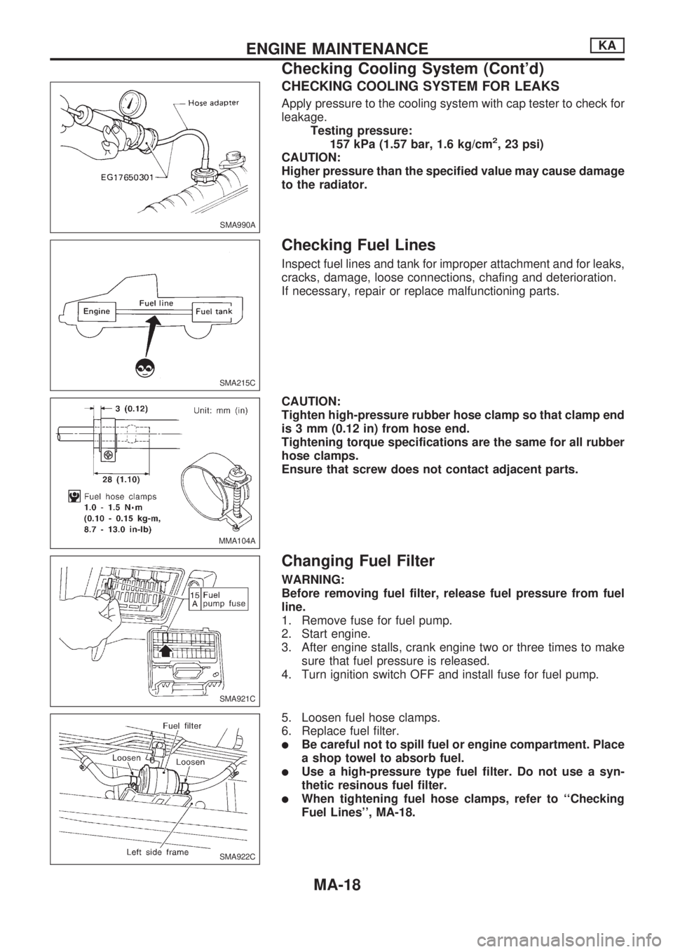
CHECKING COOLING SYSTEM FOR LEAKS
Apply pressure to the cooling system with cap tester to check for
leakage.
Testing pressure:
157 kPa (1.57 bar, 1.6 kg/cm
2, 23 psi)
CAUTION:
Higher pressure than the specified value may cause damage
to the radiator.
Checking Fuel Lines
Inspect fuel lines and tank for improper attachment and for leaks,
cracks, damage, loose connections, chafing and deterioration.
If necessary, repair or replace malfunctioning parts.
CAUTION:
Tighten high-pressure rubber hose clamp so that clamp end
is 3 mm (0.12 in) from hose end.
Tightening torque specifications are the same for all rubber
hose clamps.
Ensure that screw does not contact adjacent parts.
Changing Fuel Filter
WARNING:
Before removing fuel filter, release fuel pressure from fuel
line.
1. Remove fuse for fuel pump.
2. Start engine.
3. After engine stalls, crank engine two or three times to make
sure that fuel pressure is released.
4. Turn ignition switch OFF and install fuse for fuel pump.
5. Loosen fuel hose clamps.
6. Replace fuel filter.
lBe careful not to spill fuel or engine compartment. Place
a shop towel to absorb fuel.
lUse a high-pressure type fuel filter. Do not use a syn-
thetic resinous fuel filter.
lWhen tightening fuel hose clamps, refer to ``Checking
Fuel Lines'', MA-18.
SMA990A
SMA215C
MMA104A
SMA921C
SMA922C
ENGINE MAINTENANCEKA
Checking Cooling System (Cont'd)
MA-18
Page 1635 of 1659

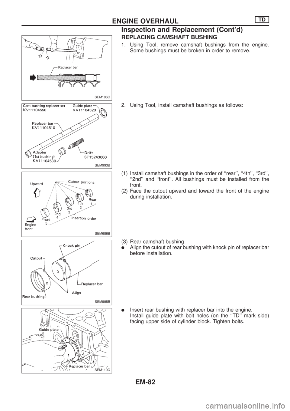
REPLACING CAMSHAFT BUSHING
1. Using Tool, remove camshaft bushings from the engine.
Some bushings must be broken in order to remove.
2. Using Tool, install camshaft bushings as follows:
(1) Install camshaft bushings in the order of ``rear'', ``4th'', ``3rd'',
``2nd'' and ``front''. All bushings must be installed from the
front.
(2) Face the cutout upward and toward the front of the engine
during installation.
(3) Rear camshaft bushing
lAlign the cutout of rear bushing with knock pin of replacer bar
before installation.
lInsert rear bushing with replacer bar into the engine.
Install guide plate with bolt holes (on the ``TD'' mark side)
facing upper side of cylinder block. Tighten bolts.
SEM106C
SEM993B
SEM686B
SEM995B
SEM110C
ENGINE OVERHAULTD
Inspection and Replacement (Cont'd)
EM-82