1998 NISSAN PICK-UP ESP
[x] Cancel search: ESPPage 2 of 1659
FOREWORD
This manual contains maintenance and repair procedures for NISSAN
PICKUP, model D22 series.
In order to assure your safety and the efficient functioning of the vehicle,
this manual should be read thoroughly. It is especially important that the
PRECAUTIONS in the GI section be completely understood before starting
any repair task.
All information in this manual is based on the latest product information
at the time of publication. The right is reserved to make changes in speci-
®cations and methods at any time without notice.
IMPORTANT SAFETY NOTICE
The proper performance of service is essential for both the safety of the
technician and the efficient functioning of the vehicle.
The service methods in this Service Manual are described in such a man-
ner that the service may be performed safely and accurately.
Service varies with the procedures used, the skills of the technician and the
tools and parts available. Accordingly, anyone using service procedures,
tools or parts which are not speci®cally recommended by NISSAN must
®rst completely satisfy himself that neither his safety nor the vehicle's
safety will be jeopardized by the service method selected.
NISSAN EUROPE S.A.S.
Service Engineering Section
Paris, France
Page 15 of 1659
Inspection
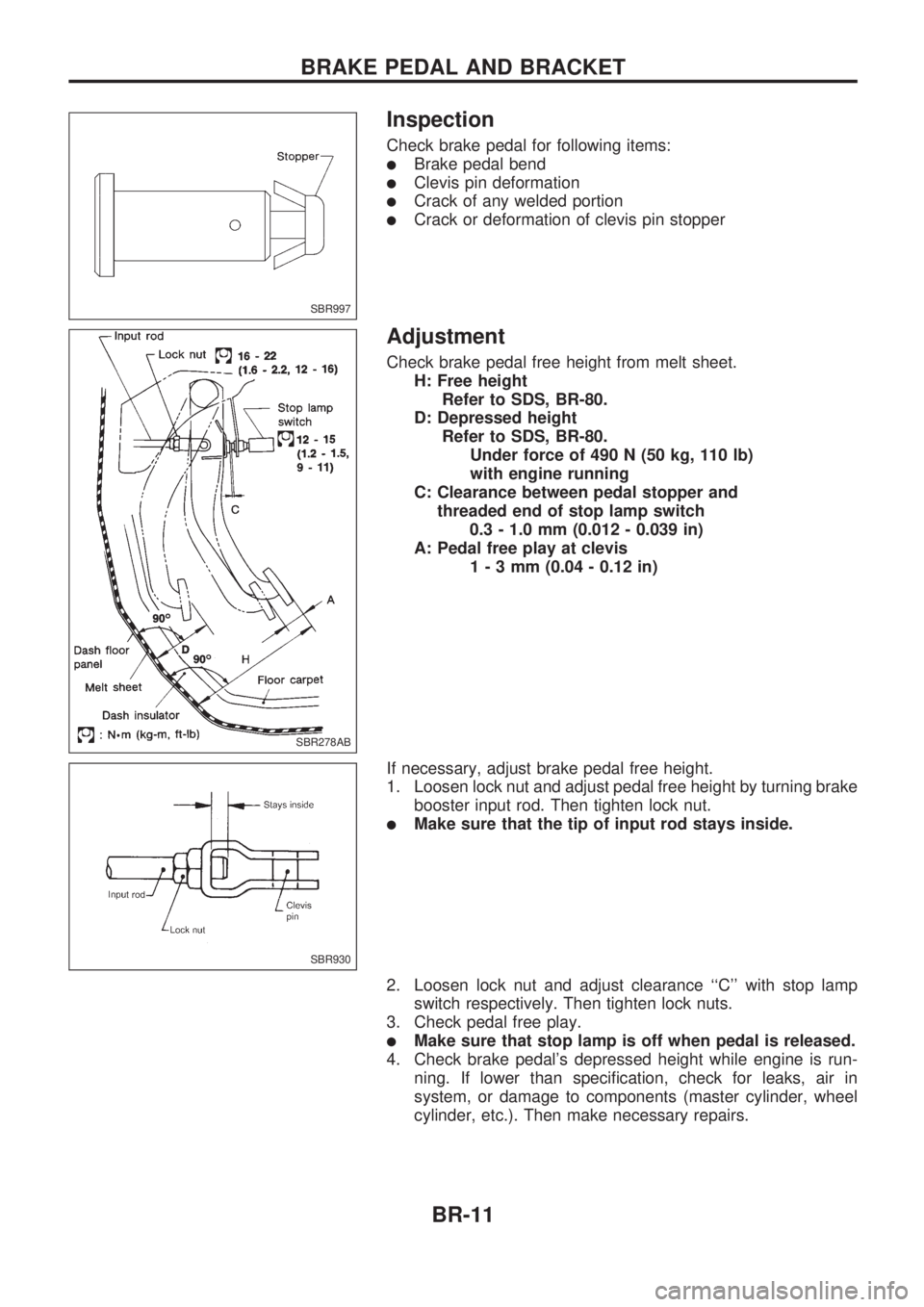
Check brake pedal for following items:
lBrake pedal bend
lClevis pin deformation
lCrack of any welded portion
lCrack or deformation of clevis pin stopper
Adjustment
Check brake pedal free height from melt sheet.
H: Free height
Refer to SDS, BR-80.
D: Depressed height
Refer to SDS, BR-80.
Under force of 490 N (50 kg, 110 lb)
with engine running
C: Clearance between pedal stopper and
threaded end of stop lamp switch
0.3 - 1.0 mm (0.012 - 0.039 in)
A: Pedal free play at clevis
1-3mm(0.04 - 0.12 in)
If necessary, adjust brake pedal free height.
1. Loosen lock nut and adjust pedal free height by turning brake
booster input rod. Then tighten lock nut.
lMake sure that the tip of input rod stays inside.
2. Loosen lock nut and adjust clearance ``C'' with stop lamp
switch respectively. Then tighten lock nuts.
3. Check pedal free play.
lMake sure that stop lamp is off when pedal is released.
4. Check brake pedal's depressed height while engine is run-
ning. If lower than specification, check for leaks, air in
system, or damage to components (master cylinder, wheel
cylinder, etc.). Then make necessary repairs.
SBR997
SBR278AB
SBR930
BRAKE PEDAL AND BRACKET
BR-11
Page 42 of 1659
How to Perform Trouble Diagnoses for Quick
and Accurate Repair
INTRODUCTION
The ABS system has an electronic control unit to control major
functions. The control unit accepts input signals from sensors
and instantly drives the actuators. It is essential that both kinds
of signals are proper and stable. It is also important to check for
conventional problems: such as air leaks in booster lines, lack of
brake fluid, or other problems with the brake system.
It is much more difficult to diagnose a problem that occurs inter-
mittently rather than continuously. Most intermittent problems are
caused by poor electric connections or faulty wiring. In this case,
careful checking of suspicious circuits may help prevent the
replacement of good parts.
A visual check only may not find the cause of the problems, so
a road test should be performed.
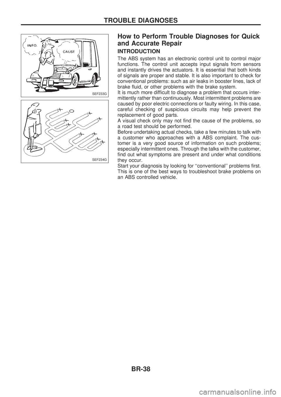
Before undertaking actual checks, take a few minutes to talk with
a customer who approaches with a ABS complaint. The cus-
tomer is a very good source of information on such problems;
especially intermittent ones. Through the talks with the customer,
find out what symptoms are present and under what conditions
they occur.
Start your diagnosis by looking for ``conventional'' problems first.
This is one of the best ways to troubleshoot brake problems on
an ABS controlled vehicle.
SEF233G
SEF234G
TROUBLE DIAGNOSES
BR-38
Page 102 of 1659
Clip and Fastener
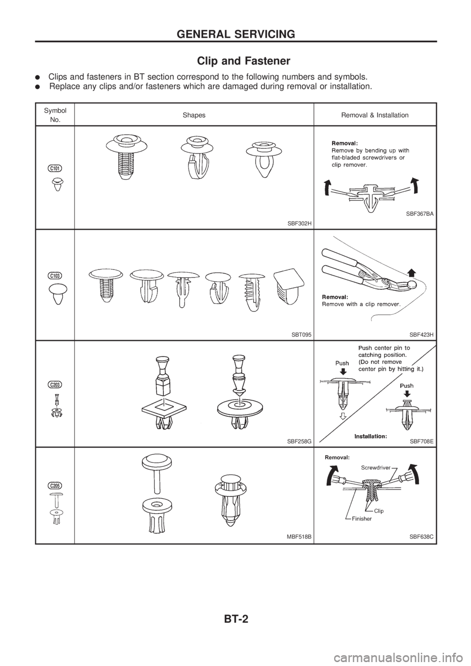
lClips and fasteners in BT section correspond to the following numbers and symbols.
lReplace any clips and/or fasteners which are damaged during removal or installation.
Symbol
No.Shapes Removal & Installation
C101
SBF302H
SBF367BA
C103
SBT095SBF423H
C203
SBF258GSBF708E
C205
MBF518BSBF638C
GENERAL SERVICING
BT-2
Page 143 of 1659
lAll dimensions indicated in figures are actual ones.
lWhen using a tracking gauge, adjust both pointers to equal length. Make sure there is no free play.
lWhen a measuring tape is used, check to be sure there is no elongation, twisting or bending.
lMeasurements should be taken at the center of the mounting holes.
lAll measurements and mounting hole diameters are expressed in millimeters (mm).
lAn asterisk (*) following the value at the measuring point indicates that the measuring point on the other
side is symmetrically the same value.
lThe coordinates of the measurement points are the distances measured from the respective dimension
lines in the directions of ``x'', ``y'' and ``z''.
Dimension lines: ``x'' line Ð Center line of vehicle
``y'' line Ð Center line of front axle (Any measurement point in front of the dimension
line refers to a minus ``Ð'' value.)
``z'' line Ð Datum line (Any measurement point under the dimension line refers to a
minus ``Ð'' value.)
2W.SB: Short wheelbase (2WD)
2W.LB
: Long wheelbase (2WD)
4W.LB
: Long wheelbase (4WD)
BODY ALIGNMENT
BT-43
Page 169 of 1659

Distributor Ignition (DI) System
INPUT/OUTPUT SIGNAL LINE
Camshaft position sensorcEngine speed and piston position
ECM
(ECCS
control
module)
cPower
transistor
Mass air flow sensorcAmount of intake air
Engine coolant temperature sensor
cEngine coolant temperature
Throttle position sensor
c
Throttle position
Throttle valve idle position
Vehicle speed sensor
cVehicle speed
Ignition switch
cStart signal
Intake air temperature sensor
cIntake air temperature
Neutral position switch
cGear position
Battery
cBattery voltage
SYSTEM DESCRIPTION
The ignition timing is controlled by the ECM to maintain the best
air-fuel ratio for every running condition of the engine.
The ignition timing data is stored in the ECM. This data forms the
map shown left.
The ECM detects information such as the injection pulse width
and camshaft position sensor signal. Responding to this
information, ignition signals are transmitted to the power transis-
tor.
e.g. N: 1,800 rpm, Tp: 1.50 msec
A ÉBTDC
During the following conditions, the ignition timing is revised by
the ECM according to the other data stored in the ECM.
1 At starting
2 During warm-up
3 At idle
4 When swirl control valve operates
5 Hot-engine operation
6 At acceleration
SEF742M
ENGINE AND EMISSION BASIC CONTROL SYSTEM DESCRIPTIONKA
EC-17
Page 205 of 1659
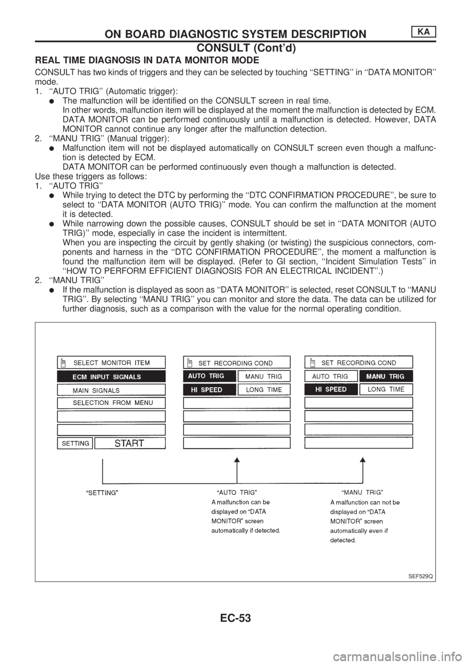
REAL TIME DIAGNOSIS IN DATA MONITOR MODE
CONSULT has two kinds of triggers and they can be selected by touching ``SETTING'' in ``DATA MONITOR''
mode.
1. ``AUTO TRIG'' (Automatic trigger):
lThe malfunction will be identified on the CONSULT screen in real time.
In other words, malfunction item will be displayed at the moment the malfunction is detected by ECM.
DATA MONITOR can be performed continuously until a malfunction is detected. However, DATA
MONITOR cannot continue any longer after the malfunction detection.
2. ``MANU TRIG'' (Manual trigger):
lMalfunction item will not be displayed automatically on CONSULT screen even though a malfunc-
tion is detected by ECM.
DATA MONITOR can be performed continuously even though a malfunction is detected.
Use these triggers as follows:
1. ``AUTO TRIG''
lWhile trying to detect the DTC by performing the ``DTC CONFIRMATION PROCEDURE'', be sure to
select to ``DATA MONITOR (AUTO TRIG)'' mode. You can confirm the malfunction at the moment
it is detected.
lWhile narrowing down the possible causes, CONSULT should be set in ``DATA MONITOR (AUTO
TRIG)'' mode, especially in case the incident is intermittent.
When you are inspecting the circuit by gently shaking (or twisting) the suspicious connectors, com-
ponents and harness in the ``DTC CONFIRMATION PROCEDURE'', the moment a malfunction is
found the malfunction item will be displayed. (Refer to GI section, ``Incident Simulation Tests'' in
``HOW TO PERFORM EFFICIENT DIAGNOSIS FOR AN ELECTRICAL INCIDENT''.)
2. ``MANU TRIG''
lIf the malfunction is displayed as soon as ``DATA MONITOR'' is selected, reset CONSULT to ``MANU
TRIG''. By selecting ``MANU TRIG'' you can monitor and store the data. The data can be utilized for
further diagnosis, such as a comparison with the value for the normal operating condition.
SEF529Q
ON BOARD DIAGNOSTIC SYSTEM DESCRIPTIONKA
CONSULT (Cont'd)
EC-53
Page 206 of 1659

Introduction
The engine has an ECM to control major systems such as fuel
control, ignition control, idle air control system, etc. The ECM
accepts input signals from sensors and instantly drives actua-
tors. It is essential that both input and output signals are proper
and stable. At the same time, it is important that there are no
problems such as vacuum leaks, fouled spark plugs, or other
problems with the engine.
It is much more difficult to diagnose a problem that occurs inter-
mittently rather than continuously. Most intermittent problems are
caused by poor electric connections or improper wiring. In this
case, careful checking of suspected circuits may help prevent the
replacement of good parts.
A visual check only may not find the cause of the problems. A
road test with CONSULT or a circuit tester connected should be
performed. Follow the ``Work Flow'' on EC-56.
Before undertaking actual checks, take just a few minutes to talk
with a customer who approaches with a driveability complaint.
The customer can supply good information about such problems,
especially intermittent ones. Find out what symptoms are present
and under what conditions they occur. A ``Diagnostic Worksheet''
like the example on next page should be used.
Start your diagnosis by looking for ``conventional'' problems first.
This will help troubleshoot driveability problems on an electroni-
cally controlled engine vehicle.
Diagnostic Worksheet
There are many operating conditions that lead to the malfunc-
tions of engine components. A good knowledge of such condi-
tions can make troubleshooting faster and more accurate.
In general, each customer may feel differently about a given
problem. It is important to fully understand the symptoms or
conditions for a customer complaint.
Utilize a diagnostic worksheet like the one on next page in order
to organize all the information for troubleshooting.
MEF036D
SEF233G
SEF234G
SEF907L
TROUBLE DIAGNOSIS Ð IntroductionKA
EC-54