1998 NISSAN PICK-UP air bleeding
[x] Cancel search: air bleedingPage 3 of 1659
BRAKE SYSTEM
SECTIONBR
CONTENTS
PRECAUTIONS AND PREPARATION..................... 1
Supplemental Restraint System (SRS) ``AIR
BAG'' (4WD models).............................................. 1
Supplemental Restraint System (SRS) ``AIR
BAG'' (2WD models).............................................. 1
Precautions for Brake System ............................... 1
Special Service Tools ............................................ 2
Commercial Service Tools ..................................... 2
CHECK AND ADJUSTMENT.................................... 3
Checking Brake Fluid Level ................................... 3
Checking Brake Line.............................................. 3
Changing Brake Fluid ............................................ 3
Bleeding Brake System ......................................... 4
BRAKE HYDRAULIC LINE....................................... 5
CONTROL VALVE..................................................... 7
Load Sensing Valve ............................................... 7
BRAKE PEDAL AND BRACKET............................ 10
Removal and Installation ..................................... 10
Inspection ............................................................. 11
Adjustment ........................................................... 11
MASTER CYLINDER............................................... 12
Removal ............................................................... 12
Disassembly ......................................................... 13
Inspection ............................................................. 13
Assembly.............................................................. 13
Installation ............................................................ 14
BRAKE BOOSTER.................................................. 15
On-vehicle Service ............................................... 15
Removal ............................................................... 15
Inspection ............................................................. 15
Installation ............................................................ 16
VACUUM HOSE...................................................... 17
Removal and Installation ..................................... 17Inspection ............................................................. 17
VACUUM PUMP...................................................... 19
Removal and Installation ..................................... 19
Inspection ............................................................. 19
FRONT DISC BRAKE............................................. 21
Pad Replacement ................................................ 21
Removal ............................................................... 22
Disassembly ......................................................... 23
Inspection - Caliper .............................................. 23
Inspection - Rotor ................................................ 23
Assembly.............................................................. 24
Installation ............................................................ 24
Brake Burnishing Procedure ................................ 24
REAR DRUM BRAKE............................................. 26
Removal ............................................................... 27
Inspection - Wheel Cylinder................................. 28
Wheel Cylinder Overhaul ..................................... 28
Inspection - Drum ................................................ 28
Inspection - Lining................................................ 28
Installation ............................................................ 28
PARKING BRAKE CONTROL................................ 30
Removal and Installation ..................................... 31
Inspection ............................................................. 31
Adjustment ........................................................... 31
ANTI-LOCK BRAKE SYSTEM................................ 32
Purpose ................................................................ 32
Operation ............................................................. 32
ABS Hydraulic Circuit .......................................... 32
System Components............................................ 33
System Description .............................................. 33
Removal and Installation ..................................... 35
TROUBLE DIAGNOSES......................................... 38
BR
Page 7 of 1659
Checking Brake Fluid Level
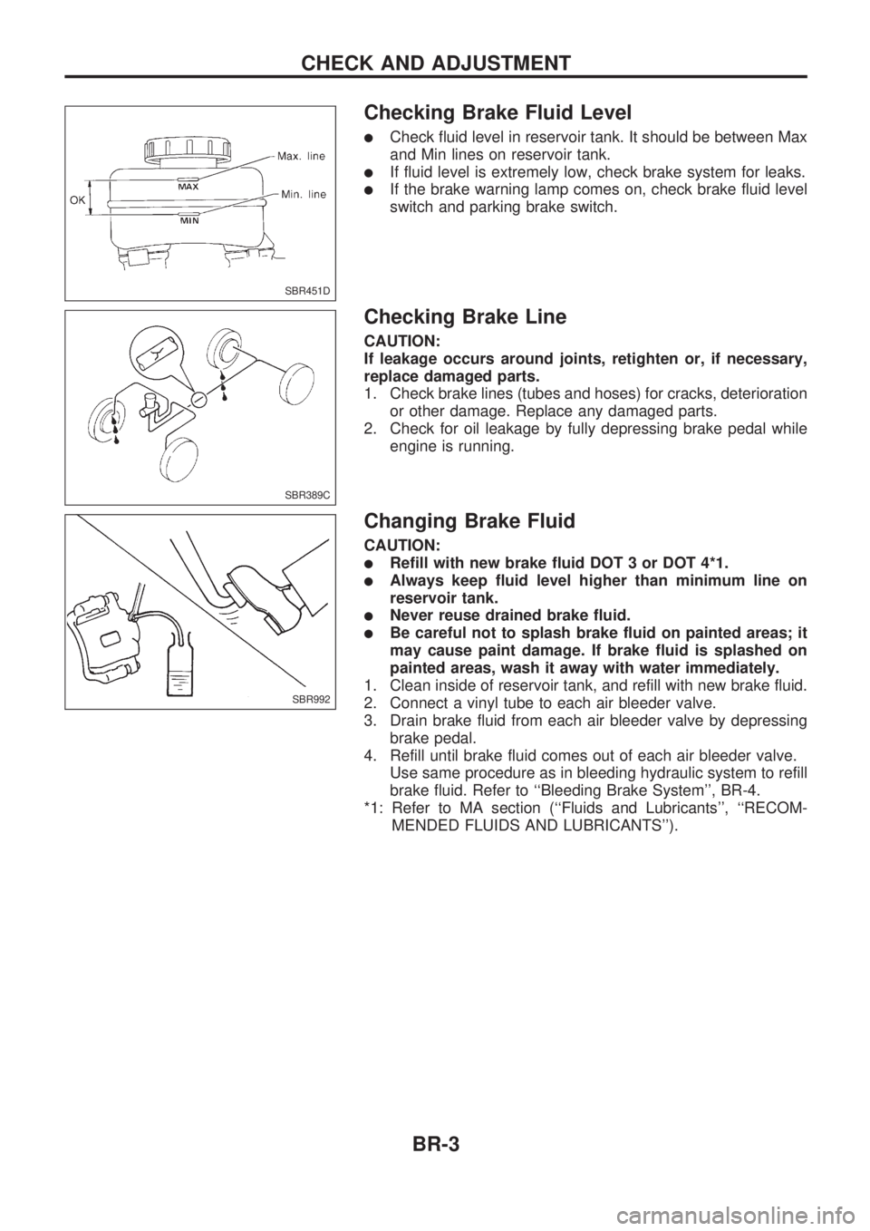
lCheck fluid level in reservoir tank. It should be between Max
and Min lines on reservoir tank.
lIf fluid level is extremely low, check brake system for leaks.
lIf the brake warning lamp comes on, check brake fluid level
switch and parking brake switch.
Checking Brake Line
CAUTION:
If leakage occurs around joints, retighten or, if necessary,
replace damaged parts.
1. Check brake lines (tubes and hoses) for cracks, deterioration
or other damage. Replace any damaged parts.
2. Check for oil leakage by fully depressing brake pedal while
engine is running.
Changing Brake Fluid
CAUTION:
lRefill with new brake fluid DOT 3 or DOT 4*1.
lAlways keep fluid level higher than minimum line on
reservoir tank.
lNever reuse drained brake fluid.
lBe careful not to splash brake fluid on painted areas; it
may cause paint damage. If brake fluid is splashed on
painted areas, wash it away with water immediately.
1. Clean inside of reservoir tank, and refill with new brake fluid.
2. Connect a vinyl tube to each air bleeder valve.
3. Drain brake fluid from each air bleeder valve by depressing
brake pedal.
4. Refill until brake fluid comes out of each air bleeder valve.
Use same procedure as in bleeding hydraulic system to refill
brake fluid. Refer to ``Bleeding Brake System'', BR-4.
*1: Refer to MA section (``Fluids and Lubricants'', ``RECOM-
MENDED FLUIDS AND LUBRICANTS'').
SBR451D
SBR389C
SBR992
CHECK AND ADJUSTMENT
BR-3
Page 8 of 1659
Bleeding Brake System
CAUTION:
lCarefully monitor brake fluid level at master cylinder
during bleeding operation.
lIf master cylinder is suspected to have air inside, bleed
air from master cylinder first. Refer to ``Installation'',
``MASTER CYLINDER'', BR-14.
lFill reservoir with new brake fluid DOT 3 or DOT 4*1.
Make sure it is full at all times while bleeding air out of
system.
lPlace a container under master cylinder to avoid spillage
of brake fluid.
lFor models with ABS, turn ignition switch OFF and dis-
connect ABS actuator connector or battery cable.
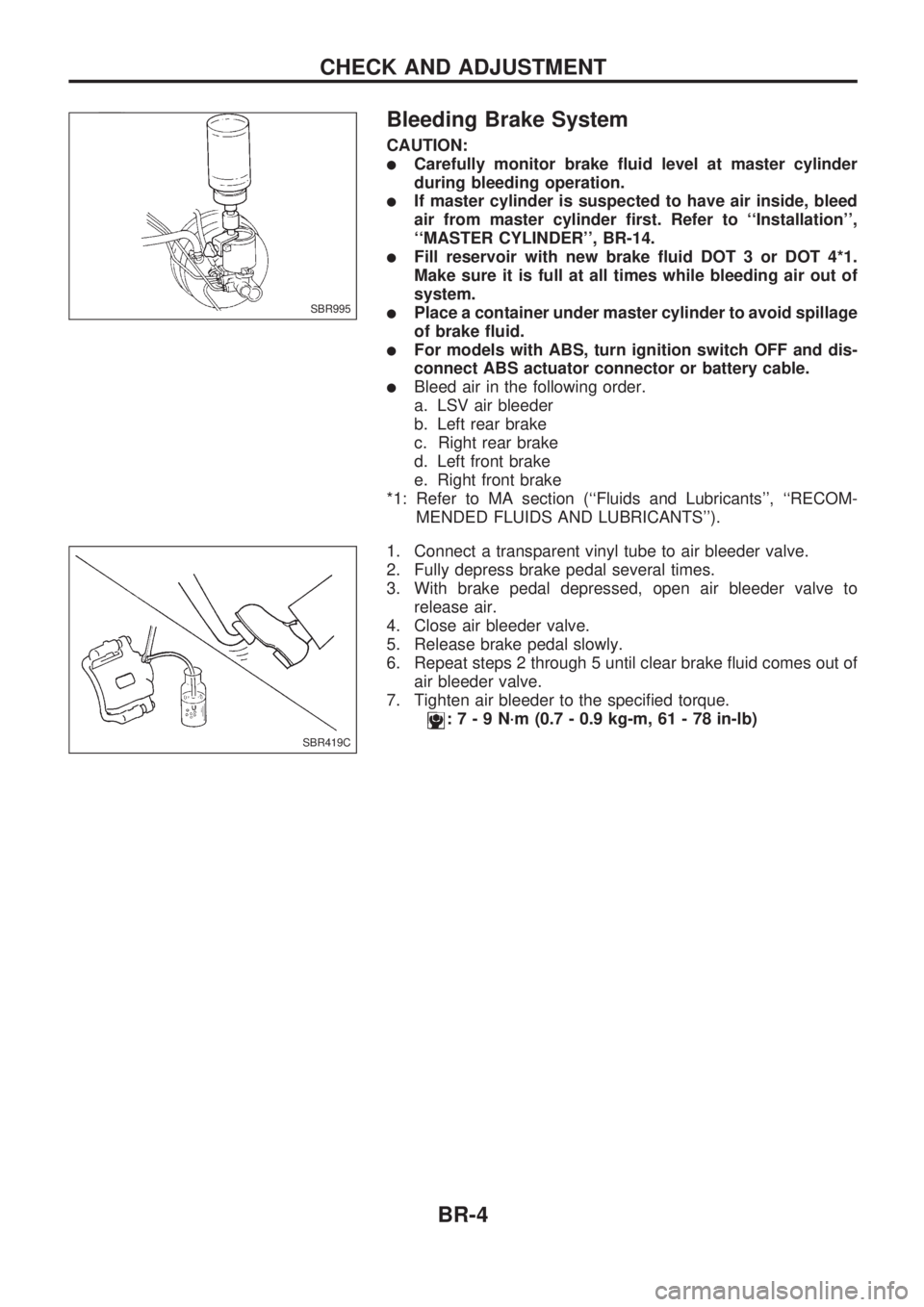
lBleed air in the following order.
a. LSV air bleeder
b. Left rear brake
c. Right rear brake
d. Left front brake
e. Right front brake
*1: Refer to MA section (``Fluids and Lubricants'', ``RECOM-
MENDED FLUIDS AND LUBRICANTS'').
1. Connect a transparent vinyl tube to air bleeder valve.
2. Fully depress brake pedal several times.
3. With brake pedal depressed, open air bleeder valve to
release air.
4. Close air bleeder valve.
5. Release brake pedal slowly.
6. Repeat steps 2 through 5 until clear brake fluid comes out of
air bleeder valve.
7. Tighten air bleeder to the specified torque.
:7-9N´m(0.7 - 0.9 kg-m, 61 - 78 in-lb)
SBR995
SBR419C
CHECK AND ADJUSTMENT
BR-4
Page 10 of 1659
REMOVAL
CAUTION:
lBe careful not to splash brake fluid on painted areas; it
may cause paint damage. If brake fluid is splashed on
painted areas, wash it away with water immediately.
lAll hoses must be free from excessive bending, twisting
and pulling.
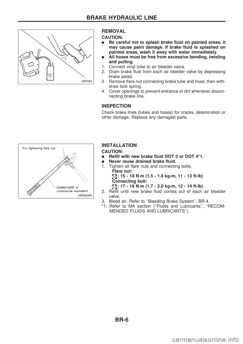
1. Connect vinyl tube to air bleeder valve.
2. Drain brake fluid from each air bleeder valve by depressing
brake pedal.
3. Remove flare nut connecting brake tube and hose, then with-
draw lock spring.
4. Cover openings to prevent entrance of dirt whenever discon-
necting brake line.
INSPECTION
Check brake lines (tubes and hoses) for cracks, deterioration or
other damage. Replace any damaged parts.
INSTALLATION
CAUTION:
lRefill with new brake fluid DOT 3 or DOT 4*1.
lNever reuse drained brake fluid.
1. Tighten all flare nuts and connecting bolts.
Flare nut:
: 15 - 18 N´m (1.5 - 1.8 kg-m, 11 - 13 ft-lb)
Connecting bolt:
: 17 - 19 N´m (1.7 - 2.0 kg-m, 12 - 14 ft-lb)
2. Refill until new brake fluid comes out of each air bleeder
valve.
3. Bleed air. Refer to ``Bleeding Brake System'', BR-4.
*1: Refer to MA section (``Fluids and Lubricants'', ``RECOM-
MENDED FLUIDS AND LUBRICANTS'').
SBR992
SBR820BA
BRAKE HYDRAULIC LINE
BR-6
Page 12 of 1659
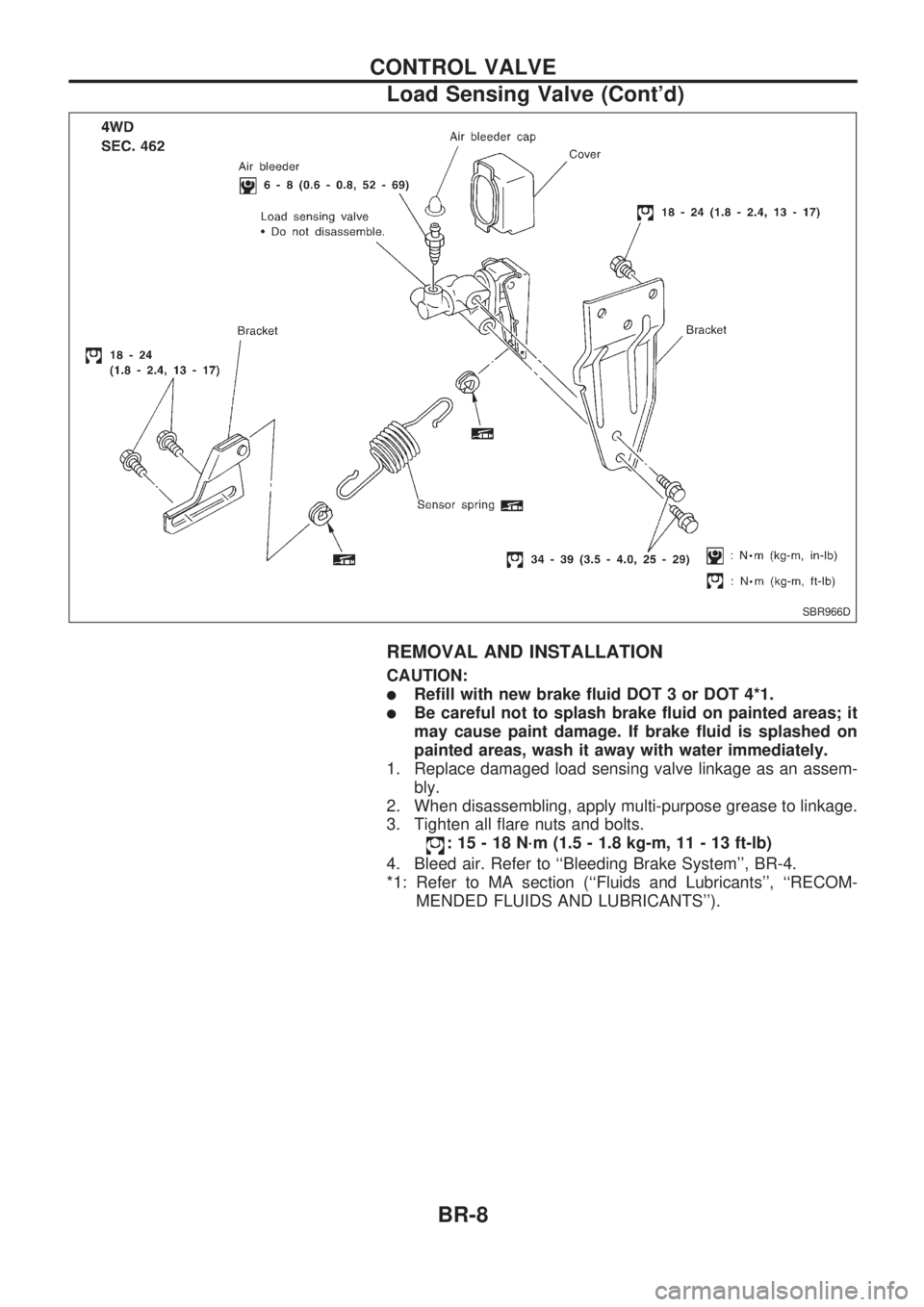
REMOVAL AND INSTALLATION
CAUTION:
lRefill with new brake fluid DOT 3 or DOT 4*1.
lBe careful not to splash brake fluid on painted areas; it
may cause paint damage. If brake fluid is splashed on
painted areas, wash it away with water immediately.
1. Replace damaged load sensing valve linkage as an assem-
bly.
2. When disassembling, apply multi-purpose grease to linkage.
3. Tighten all flare nuts and bolts.
: 15 - 18 N´m (1.5 - 1.8 kg-m, 11 - 13 ft-lb)
4. Bleed air. Refer to ``Bleeding Brake System'', BR-4.
*1: Refer to MA section (``Fluids and Lubricants'', ``RECOM-
MENDED FLUIDS AND LUBRICANTS'').
SBR966D
CONTROL VALVE
Load Sensing Valve (Cont'd)
BR-8
Page 18 of 1659
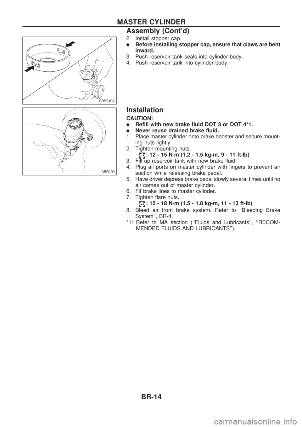
2. Install stopper cap.
lBefore installing stopper cap, ensure that claws are bent
inward.
3. Push reservoir tank seals into cylinder body.
4. Push reservoir tank into cylinder body.
Installation
CAUTION:
lRefill with new brake fluid DOT 3 or DOT 4*1.
lNever reuse drained brake fluid.
1. Place master cylinder onto brake booster and secure mount-
ing nuts lightly.
2. Tighten mounting nuts.
: 12 - 15 N´m (1.2 - 1.5 kg-m,9-11ft-lb)
3. Fill up reservoir tank with new brake fluid.
4. Plug all ports on master cylinder with fingers to prevent air
suction while releasing brake pedal.
5. Have driver depress brake pedal slowly several times until no
air comes out of master cylinder.
6. Fit brake lines to master cylinder.
7. Tighten flare nuts.
: 15 - 18 N´m (1.5 - 1.8 kg-m, 11 - 13 ft-lb)
8. Bleed air from brake system. Refer to ``Bleeding Brake
System'', BR-4.
*1: Refer to MA section (``Fluids and Lubricants'', ``RECOM-
MENDED FLUIDS AND LUBRICANTS'').
SBR940A
ABR190
MASTER CYLINDER
Assembly (Cont'd)
BR-14
Page 20 of 1659
Installation
CAUTION:
lBe careful not to deform or bend brake pipes during
installation of booster.
lReplace clevis pin if damaged.
lRefill with new brake fluid DOT 3 or DOT 4*1.
lNever reuse drained brake fluid.
lTake care not to damage brake booster mounting bolt
thread when installing. Due to the narrow angle of
installation, the threads can be damaged by the dash
panel.
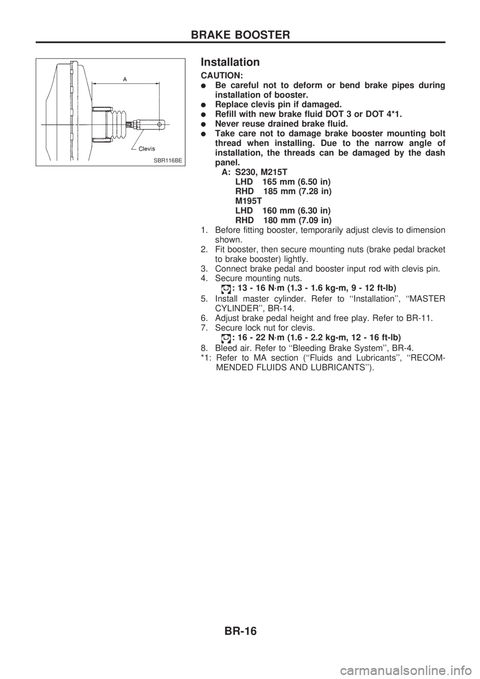
A: S230, M215T
LHD 165 mm (6.50 in)
RHD 185 mm (7.28 in)
M195T
LHD 160 mm (6.30 in)
RHD 180 mm (7.09 in)
1. Before fitting booster, temporarily adjust clevis to dimension
shown.
2. Fit booster, then secure mounting nuts (brake pedal bracket
to brake booster) lightly.
3. Connect brake pedal and booster input rod with clevis pin.
4. Secure mounting nuts.
: 13 - 16 N´m (1.3 - 1.6 kg-m,9-12ft-lb)
5. Install master cylinder. Refer to ``Installation'', ``MASTER
CYLINDER'', BR-14.
6. Adjust brake pedal height and free play. Refer to BR-11.
7. Secure lock nut for clevis.
: 16 - 22 N´m (1.6 - 2.2 kg-m, 12 - 16 ft-lb)
8. Bleed air. Refer to ``Bleeding Brake System'', BR-4.
*1: Refer to MA section (``Fluids and Lubricants'', ``RECOM-
MENDED FLUIDS AND LUBRICANTS'').
SBR116BE
BRAKE BOOSTER
BR-16
Page 28 of 1659
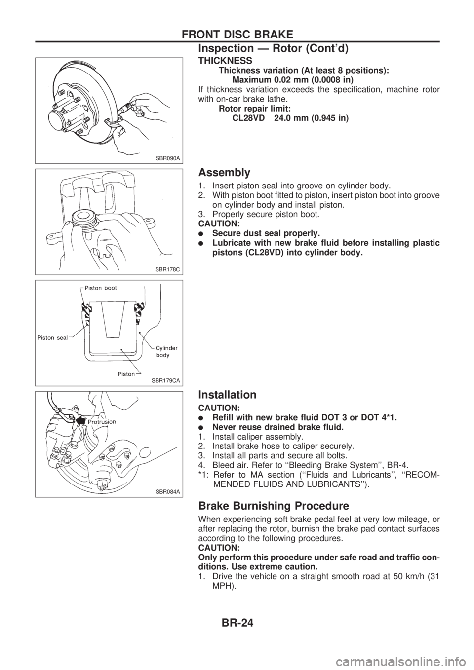
THICKNESS
Thickness variation (At least 8 positions):
Maximum 0.02 mm (0.0008 in)
If thickness variation exceeds the specification, machine rotor
with on-car brake lathe.
Rotor repair limit:
CL28VD 24.0 mm (0.945 in)
Assembly
1. Insert piston seal into groove on cylinder body.
2. With piston boot fitted to piston, insert piston boot into groove
on cylinder body and install piston.
3. Properly secure piston boot.
CAUTION:
lSecure dust seal properly.
lLubricate with new brake fluid before installing plastic
pistons (CL28VD) into cylinder body.
Installation
CAUTION:
lRefill with new brake fluid DOT 3 or DOT 4*1.
lNever reuse drained brake fluid.
1. Install caliper assembly.
2. Install brake hose to caliper securely.
3. Install all parts and secure all bolts.
4. Bleed air. Refer to ``Bleeding Brake System'', BR-4.
*1: Refer to MA section (``Fluids and Lubricants'', ``RECOM-
MENDED FLUIDS AND LUBRICANTS'').
Brake Burnishing Procedure
When experiencing soft brake pedal feel at very low mileage, or
after replacing the rotor, burnish the brake pad contact surfaces
according to the following procedures.
CAUTION:
Only perform this procedure under safe road and traffic con-
ditions. Use extreme caution.
1. Drive the vehicle on a straight smooth road at 50 km/h (31
MPH).
SBR090A
SBR178C
SBR179CA
SBR084A
FRONT DISC BRAKE
Inspection Ð Rotor (Cont'd)
BR-24