1998 NISSAN PICK-UP air bleeding
[x] Cancel search: air bleedingPage 864 of 1659
A
A/C HFC134a (R134a) system precaution .....HA-2
A/C HFC134a (R134a) system service
procedure ................................................. HA-48
A/C HFC134a (R134a) system service
tools............................................................ HA-8
A/C HFC134a system service
equipment precaution .............................. HA-10
A/C air flow .................................................. HA-14
A/C component layout ................................. HA-13
A/C compressor clutch removal and
installation ................................................ HA-60
A/C compressor precaution ........................... HA-6
A/C compressor special service tool ............. HA-6
A/C control linkage adjustment
(manual A/C) ............................................ HA-45
A/C control operation (manual A/C) ............ HA-16
A/C diagnostic work flow
(manual A/C) ............................................ HA-17
A/C lubricant (R134a) .................................. HA-50
A/C operational check ................................. HA-18
A/C performance chart ................................ HA-26
A/C performance test diagnoses ................. HA-24
A/C relay ...................................................... HA-44
A/C switch.............................................. HA-16, 43
A/C symptom chart (manual A/C) ............... HA-20
A/C trouble diagnoses (manual A/C)........... HA-17
AAC/V - Wiring diagram ............................ EC-133
ABS (anti-lock brake system) ...................... BR-32
ABS - Wiring diagram .................................. BR-42
Accelerator control system............................. FE-1
Accelerator wire adjustment........................... FE-2
Air bag disposal ........................................... RS-14
Air bag precautions ......................................... GI-1
Air bag ........................................................... RS-6
Air bleeding (hydraulic clutch)........................ CL-5
Air bleeding for brake system........................ BR-4
Air cleaner filter replacement
(KA24 engine).......................................... MA-19
Air cleaner filter replacement
(TD25 engine).......................................... MA-29
Air conditioner cut control ............................ EC-18
Air flow meter - See Mass air flow
sensor ...................................................... EC-89
Alternator ...................................................... EL-41
Angular tightening application ....................... EM-1
Antenna ...................................................... EL-146
Anti-lock brake system - Wiring
diagram .................................................... BR-42
Audio and A/C control removal and
installation - See Instrument panel .......... BT-12
Auto-lock free-running hub........................... FA-15
Auxiliary air control (AAC) valve................ EC-131
Axle housing (rear) ........................................ RA-5
B
Back window .................................................BT-24Back-up lamp switch (M/T)............................ MT-9
Ball joint front axle ....................................... FA-34
Battery .......................................................... EL-18
Baulk ring (M/T) (FS5R30A)........................ MT-36
Baulk ring (M/T) (FS5W71C)....................... MT-15
Blower motor................................................ HA-43
Blower resistor ............................................. HA-43
Body alignment ............................................ BT-43
Body mounting ............................................. BT-41
Boring/horning cylinder block ...................... EM-41
Brake booster .............................................. BR-15
Brake fluid change ......................................... BR-3
Brake fluid level and line check..................... BR-3
Brake fluid level ........................................... MA-35
Brake hydraulic line ....................................... BR-5
Brake inspection .......................................... MA-36
Brake lines and cables inspection .............. MA-35
Brake lining wear temporary checking ........ MA-37
Brake master cylinder .................................. BR-12
Brake pedal.................................................. BR-10
Bulb specifications...................................... EL-252
Bumper, front ................................................. BT-5
Bumper, rear .................................................. BT-8
C
CHARGE - Wiring diagram ...........................EL-34
CIGAR - Wiring diagram ............................ EL-133
CLOCK - Wiring diagram ........................... EL-134
CMPS - Wiring diagram............................... EC-85
CONSULT for ECCS ................................... EC-45
CONSULT general information ..................... GI-34
Cab body ...................................................... BT-40
Camshaft inspection (KA24 engine) ........... EM-28
Camshaft inspection (TD25 engine) ........... EM-85
Camshaft position sensor (CMPS) .............. EC-82
Canister - See EVAP canister ..................... EC-19
Center bearing assembly
(propeller shaft) ........................................ PD-10
Center bearing disassembly
(propeller shaft) .......................................... PD-9
Center case (Transfer) ................................... TF-8
Charging system .......................................... EL-34
Chassis and body maintenance .................. MA-32
Cigarette lighter .......................................... EL-133
Circuit breaker .............................................. EL-13
Clock........................................................... EL-134
Clutch cover ................................................. CL-13
Clutch disc.................................................... CL-12
Clutch fluid level .......................................... MA-32
Clutch master cylinder ................................... CL-6
Clutch operating cylinder ............................... CL-8
Clutch pedal ................................................... CL-4
Clutch release bearing ................................... CL-9
Clutch release mechanism............................. CL-9
Clutch withdrawal lever .................................. CL-9
Collision diagnosis (2WD models)............... RS-21
Collision diagnosis (4WD models)............... RS-42
ALPHABETICAL INDEX
IDX-2
Page 868 of 1659
Maintenance (engine) (TD25 engine) ......... MA-23
Major overhaul (Transfer)............................... TF-8
Malfunction indicator lamp (MIL) ................. EC-38
Manifold tightening torque (intake &
exhaust) ................................................... MA-23
Manual-lock free-running hub ...................... FA-14
Manual steering gear ................................... ST-13
Manual transmission number........................ GI-43
Manual transmission oil replacement.......... MA-32
Mass air flow sensor (MAFS) ...................... EC-89
Master cylinder (brake) ................................ BR-12
Master cylinder (clutch) .................................. CL-6
Mirror, door................................................... BT-39
Mode door control linkage adjustment ........ HA-46
Model variation.............................................. GI-37
Molding - See Exterior ................................. BT-24
Multi-remote control system ....................... EL-173
Multiport fuel injection (MFI) system ........... EC-14
N
NATS (Nissan Anti-theft System)
precautions .......................................................GI-2
NATS (Nissan Anti-theft System)............... EL-183
NATS - Wiring diagram .............................. EL-185
Neutral position switch (M/T)....................... MT-14
Neutral position switch............................... EC-136
O
Oil change (capacity)....................................MA-12
Oil change (interval) ...................................... MA-5
Oil cooler (engine)........................................ LC-17
Oil jet ............................................................ LC-18
Oil pan (engine) (KA24 engine) .................. EM-11
Oil pan (engine) (TD25 engine) .................. EM-52
Oil pressure (engine) (KA24 engine) ............. LC-4
Oil pressure (engine) (TD25 engine) ........... LC-13
Oil pressure relief valve (engine)
(KA24 engine) ............................................ LC-5
Oil pressure relief valve (engine)
(TD25 engine) .......................................... LC-16
Oil pump (engine) (KA24 engine) .................. LC-4
Oil pump (engine) (TD25 engine) ................ LC-14
Oil pump regulator valve (engine)
(KA24 engine) ............................................ LC-5
Oil pump regulator valve (engine)
(TD25 engine) .......................................... LC-17
Oil seal replacement (engine)
(KA24 engine).......................................... EM-22
Oil seal replacement (engine)
(TD25 engine).......................................... EM-67
Oil seal replacement (front of final
drive) ........................................................ PD-12
Operating cylinder (clutch) ............................. CL-8
Outside mirror - See Door mirror ................. BT-39
Oversize piston............................................ EM-95
P
P/ANT - Wiring diagram ..............................EL-147
PCV (positive crankcase ventilation) ......... EC-193
PCV filter replacement ................................ MA-21
PCV system inspection ............................... MA-21
PGC/V - Wiring diagram ............................ EC-141
PLA - Wiring diagram ................................ EC-222
PNP/SW - Wiring diagram ......................... EC-137
POWER - Wiring diagram .............................. EL-6
PST/SW - Wiring diagram ......................... EC-157
Pantograph jack ............................................ GI-47
Parking brake control................................... BR-30
Parking lamp ................................................ EL-66
Periodic maintenance .................................... MA-5
Pilot bushing replacement
(KA24 engine).......................................... EM-48
Pilot bushing replacement
(TD25 engine).......................................... EM-79
Piston assembly (KA24 engine) .................. EM-45
Piston assembly (TD25 engine) .................. EM-86
Piston pin inspection (KA24 engine) ........... EM-39
Piston pin inspection (TD25 engine) ........... EM-76
Piston ring inspection (KA24 engine).......... EM-40
Piston ring inspection (TD25 engine).......... EM-76
Piston to bore clearance
(KA24 engine).......................................... EM-41
Piston to bore clearance
(TD25 engine).......................................... EM-75
Power door lock ......................................... EL-166
Power door mirror ...................................... EL-150
Power steering fluid level .................. MA-37, ST-4
Power steering gear (PB48S) ...................... ST-20
Power steering gear (PB59K) ...................... ST-28
Power steering hydraulic system ................... ST-7
Power steering oil pressure switch............ EC-157
Power steering oil pump .............................. ST-34
Power steering system bleeding .................... ST-5
Power supply routing...................................... EL-5
Power transistor & ignition coil .................. EC-105
Power window ............................................ EL-154
Pre-delivery inspection .................................. MA-3
Precautions (General) ..................................... GI-2
Pressure plate - See Clutch cover............... CL-13
Priming pump............................................. EC-192
Propeller shaft................................................ PD-6
Propeller shaft greasing .............................. MA-33
Propeller shaft inspection ............................ MA-33
Propeller shaft vibration ................................. PD-8
Push rod ...................................................... EM-60
Q
Quick-glow system check ...........................EC-203
R
R/FOG - Wiring diagram ...............................EL-72
ALPHABETICAL INDEX
IDX-6
Page 1001 of 1659
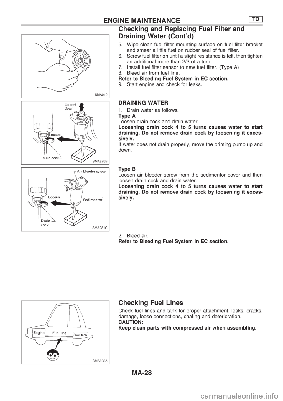
5. Wipe clean fuel filter mounting surface on fuel filter bracket
and smear a little fuel on rubber seal of fuel filter.
6. Screw fuel filter on until a slight resistance is felt, then tighten
an additional more than 2/3 of a turn.
7. Install fuel filter sensor to new fuel filter. (Type A)
8. Bleed air from fuel line.
Refer to Bleeding Fuel System in EC section.
9. Start engine and check for leaks.
DRAINING WATER
1. Drain water as follows.
Type A
Loosen drain cock and drain water.
Loosening drain cock 4 to 5 turns causes water to start
draining. Do not remove drain cock by loosening it exces-
sively.
If water does not drain properly, move the priming pump up and
down.
Type B
Loosen air bleeder screw from the sedimentor cover and then
loosen drain cock and drain water.
Loosening drain cock 4 to 5 turns causes water to start
draining. Do not remove drain cock by loosening it exces-
sively.
2. Bleed air.
Refer to Bleeding Fuel System in EC section.
Checking Fuel Lines
Check fuel lines and tank for proper attachment, leaks, cracks,
damage, loose connections, chafing and deterioration.
CAUTION:
Keep clean parts with compressed air when assembling.
SMA010
SMA825B
SMA281C
SMA803A
ENGINE MAINTENANCETD
Checking and Replacing Fuel Filter and
Draining Water (Cont'd)
MA-28
Page 1008 of 1659
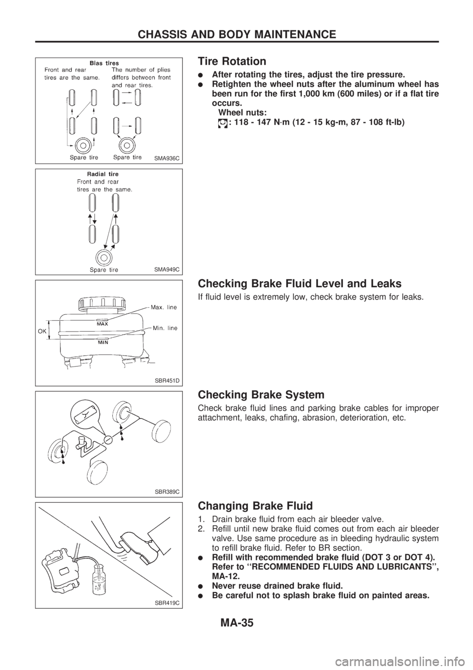
Tire Rotation
lAfter rotating the tires, adjust the tire pressure.
lRetighten the wheel nuts after the aluminum wheel has
been run for the first 1,000 km (600 miles) or if a flat tire
occurs.
Wheel nuts:
: 118 - 147 N´m (12 - 15 kg-m, 87 - 108 ft-lb)
Checking Brake Fluid Level and Leaks
If fluid level is extremely low, check brake system for leaks.
Checking Brake System
Check brake fluid lines and parking brake cables for improper
attachment, leaks, chafing, abrasion, deterioration, etc.
Changing Brake Fluid
1. Drain brake fluid from each air bleeder valve.
2. Refill until new brake fluid comes out from each air bleeder
valve. Use same procedure as in bleeding hydraulic system
to refill brake fluid. Refer to BR section.
lRefill with recommended brake fluid (DOT 3 or DOT 4).
Refer to ``RECOMMENDED FLUIDS AND LUBRICANTS'',
MA-12.
lNever reuse drained brake fluid.
lBe careful not to splash brake fluid on painted areas.
SMA936C
SMA949C
SBR451D
SBR389C
SBR419C
CHASSIS AND BODY MAINTENANCE
MA-35
Page 1222 of 1659
STEERING SYSTEM
SECTIONST
CONTENTS
PRECAUTIONS AND PREPARATION..................... 1
Supplemental Restraint System (SRS) ``AIR
BAG'' (4WD models).............................................. 1
Supplemental Restraint System (SRS) ``AIR
BAG'' (2WD models).............................................. 1
Precautions for Steering System ........................... 1
Special Service Tools ............................................ 2
ON-VEHICLE SERVICE............................................ 4
Steering System..................................................... 4
Checking and Adjusting Drive Belts (For
power steering) ...................................................... 4
Checking Fluid Level (For power steering) ........... 4
Checking Fluid Leakage (For power steering) ...... 5
Bleeding Hydraulic System (For power
steering) ................................................................. 5
Checking Steering Wheel Turning Force (For
power steering) ...................................................... 6
Checking Steering Wheel Play .............................. 6
Checking Neutral Position on Steering Wheel ...... 7
Checking Front Wheel Turning Angle ................... 7
Checking Hydraulic System (For power
steering) ................................................................. 7
STEERING WHEEL AND STEERING COLUMN..... 9
Steering Wheel ...................................................... 9
Steering Column .................................................. 10
Disassembly and Assembly ................................. 11
Inspection ............................................................. 12
MANUAL STEERING GEAR (Model: VB66K)....... 13
Removal and Installation ..................................... 13
Disassembly ......................................................... 14
Assembly and Adjustment ................................... 14Inspection ............................................................. 17
POWER STEERING SYSTEM (Model: PB48S)..... 19
Description ........................................................... 19
POWER STEERING GEAR (Model: PB48S)......... 20
Removal and Installation ..................................... 20
Power Steering Gear Component ....................... 20
Pre-disassembly Inspection and Adjustment....... 21
Disassembly ......................................................... 22
Assembly.............................................................. 24
POWER STEERING SYSTEM (Model: PB59K).... 27
Description ........................................................... 27
POWER STEERING GEAR (Model: PB59K)......... 28
Removal and Installation ..................................... 28
Power Steering Gear Component ....................... 28
Pre-disassembly Inspection and Adjustment....... 29
Disassembly ......................................................... 30
Assembly.............................................................. 31
POWER STEERING OIL PUMP.............................. 34
Disassembly and Assembly ................................. 34
Pre-disassembly Inspection ................................. 34
Inspection ............................................................. 35
Disassembly ......................................................... 35
Assembly.............................................................. 36
STEERING LINKAGE.............................................. 37
Removal and Installation ..................................... 37
Disassembly ......................................................... 38
Inspection ............................................................. 39
SERVICE DATA AND SPECIFICATIONS (SDS)... 40
General Specifications ......................................... 40
Inspection and Adjustment .................................. 40
ST
Page 1227 of 1659
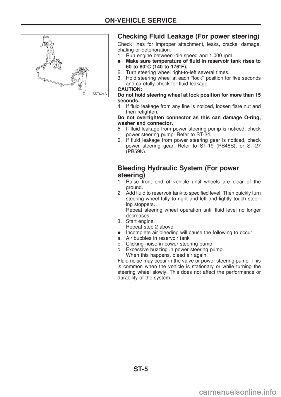
Checking Fluid Leakage (For power steering)
Check lines for improper attachment, leaks, cracks, damage,
chafing or deterioration.
1. Run engine between idle speed and 1,000 rpm.
lMake sure temperature of fluid in reservoir tank rises to
60 to 80ÉC (140 to 176ÉF).
2. Turn steering wheel right-to-left several times.
3. Hold steering wheel at each ``lock'' position for five seconds
and carefully check for fluid leakage.
CAUTION:
Do not hold steering wheel at lock position for more than 15
seconds.
4. If fluid leakage from any line is noticed, loosen flare nut and
then retighten.
Do not overtighten connector as this can damage O-ring,
washer and connector.
5. If fluid leakage from power steering pump is noticed, check
power steering pump. Refer to ST-34.
6. If fluid leakage from power steering gear is noticed, check
power steering gear. Refer to ST-19 (PB48S), or ST-27
(PB59K).
Bleeding Hydraulic System (For power
steering)
1. Raise front end of vehicle until wheels are clear of the
ground.
2. Add fluid to reservoir tank to specified level. Then quickly turn
steering wheel fully to right and left and lightly touch steer-
ing stoppers.
Repeat steering wheel operation until fluid level no longer
decreases.
3. Start engine.
Repeat step 2 above.
lIncomplete air bleeding will cause the following to occur:
a. Air bubbles in reservoir tank
b. Clicking noise in power steering pump
c. Excessive buzzing in power steering pump
When this happens, bleed air again.
Fluid noise may occur in the valve or power steering pump. This
is common when the vehicle is stationary or while turning the
steering wheel slowly. This does not affect the performance or
durability of the system.
SST621A
ON-VEHICLE SERVICE
ST-5
Page 1229 of 1659
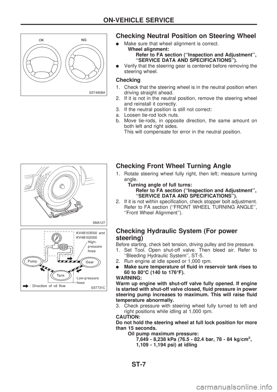
Checking Neutral Position on Steering Wheel
lMake sure that wheel alignment is correct.
Wheel alignment:
Refer to FA section (``Inspection and Adjustment'',
``SERVICE DATA AND SPECIFICATIONS'').
lVerify that the steering gear is centered before removing the
steering wheel.
Checking
1. Check that the steering wheel is in the neutral position when
driving straight ahead.
2. If it is not in the neutral position, remove the steering wheel
and reinstall it correctly.
3. If the neutral position is still not correct:
a. Loosen tie-rod lock nuts.
b. Move tie-rods, in opposite direction, the same amount on
both left and right sides.
This will compensate for error in the neutral position.
Checking Front Wheel Turning Angle
1. Rotate steering wheel fully right, then left; measure turning
angle.
Turning angle of full turns:
Refer to FA section (``Inspection and Adjustment'',
``SERVICE DATA AND SPECIFICATIONS'').
2. If it is not within specification, check stopper bolt adjustment.
Refer to FA section (``FRONT WHEEL TURNING ANGLE'',
``Front Wheel Alignment'').
Checking Hydraulic System (For power
steering)
Before starting, check belt tension, driving pulley and tire pressure.
1. Set Tool. Open shut-off valve. Then bleed air. Refer to
``Bleeding Hydraulic System'', ST-5.
2. Run engine at idle speed or 1,000 rpm.
lMake sure temperature of fluid in reservoir tank rises to
60 to 80ÉC (140 to 176ÉF).
WARNING:
Warm up engine with shut-off valve fully opened. If engine
is started with shut-off valve closed, fluid pressure in power
steering pump increases to maximum. This will raise fluid
temperature abnormally.
3. Check pressure with steering wheel fully turned to left and
right positions while idling at 1,000 rpm.
CAUTION:
Do not hold the steering wheel at full lock position for more
than 15 seconds.
Oil pump maximum pressure:
7,649 - 8,238 kPa (76.5 - 82.4 bar, 78 - 84 kg/cm
2,
1,109 - 1,194 psi) at idling
SST490BA
SMA127
SST731C
ON-VEHICLE SERVICE
ST-7