1998 NISSAN PICK-UP recommended oil
[x] Cancel search: recommended oilPage 86 of 1659
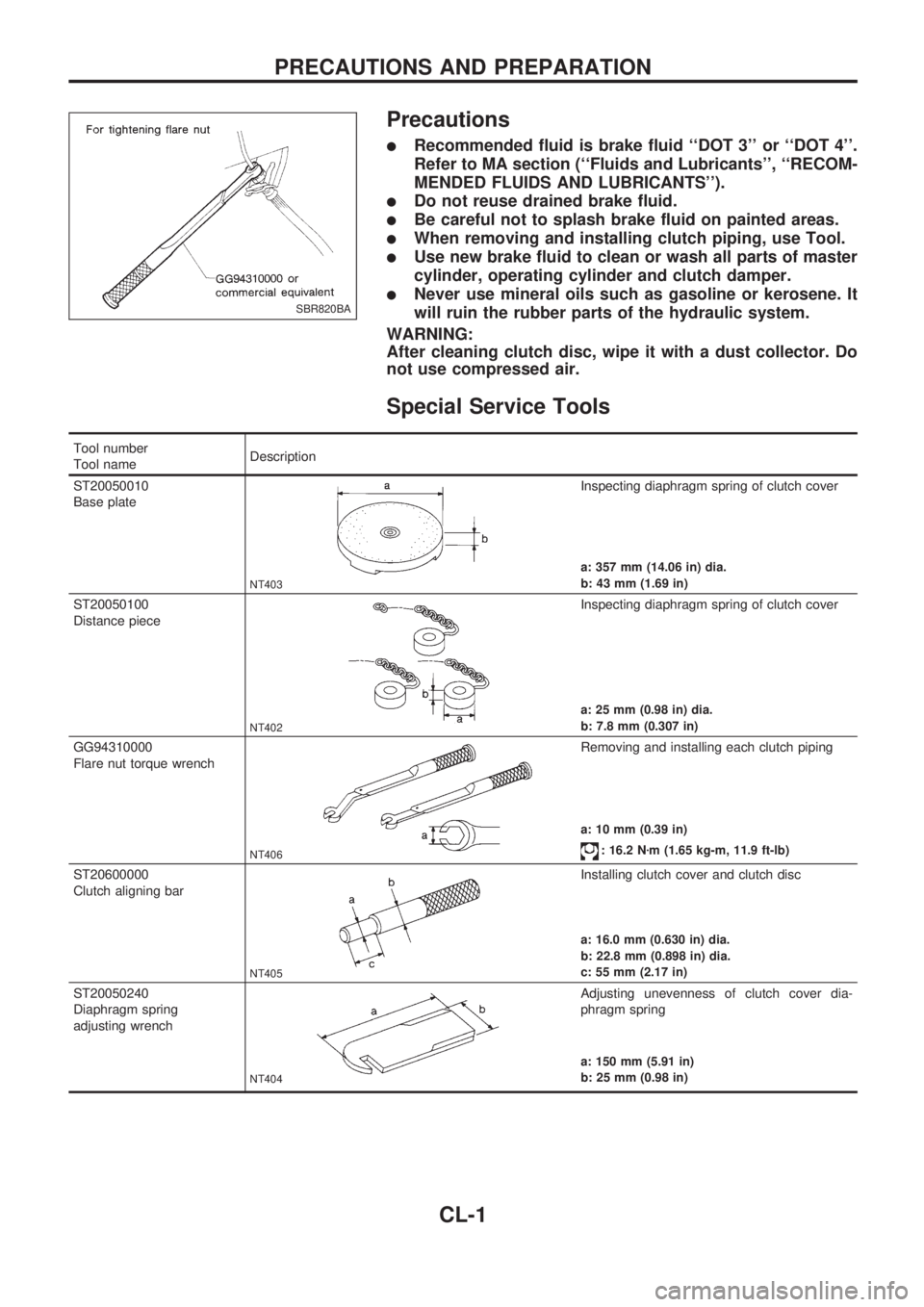
Precautions
lRecommended fluid is brake fluid ``DOT 3'' or ``DOT 4''.
Refer to MA section (``Fluids and Lubricants'', ``RECOM-
MENDED FLUIDS AND LUBRICANTS'').
lDo not reuse drained brake fluid.
lBe careful not to splash brake fluid on painted areas.
lWhen removing and installing clutch piping, use Tool.
lUse new brake fluid to clean or wash all parts of master
cylinder, operating cylinder and clutch damper.
lNever use mineral oils such as gasoline or kerosene. It
will ruin the rubber parts of the hydraulic system.
WARNING:
After cleaning clutch disc, wipe it with a dust collector. Do
not use compressed air.
Special Service Tools
Tool number
Tool nameDescription
ST20050010
Base plate
NT403
Inspecting diaphragm spring of clutch cover
a: 357 mm (14.06 in) dia.
b: 43 mm (1.69 in)
ST20050100
Distance piece
NT402
Inspecting diaphragm spring of clutch cover
a: 25 mm (0.98 in) dia.
b: 7.8 mm (0.307 in)
GG94310000
Flare nut torque wrench
NT406
Removing and installing each clutch piping
a: 10 mm (0.39 in)
: 16.2 Nzm (1.65 kg-m, 11.9 ft-lb)
ST20600000
Clutch aligning bar
NT405
Installing clutch cover and clutch disc
a: 16.0 mm (0.630 in) dia.
b: 22.8 mm (0.898 in) dia.
c: 55 mm (2.17 in)
ST20050240
Diaphragm spring
adjusting wrench
NT404
Adjusting unevenness of clutch cover dia-
phragm spring
a: 150 mm (5.91 in)
b: 25 mm (0.98 in)
SBR820BA
PRECAUTIONS AND PREPARATION
CL-1
Page 258 of 1659
Overheat
ON BOARD DIAGNOSIS LOGIC
If the cooling fan or another component in the cooling system malfunctions, the engine coolant temperature
will rise.
When the engine coolant temperature reaches an abnormally high temperature condition, a malfunction is
indicated.
Diagnostic trouble
code No.Malfunction is detected when ...Check Items
(Possible Cause)
28
lEngine coolant temperature reaches an abnormally
high temperature.lCooling fan
lRadiator hose
lRadiator
lRadiator cap
lWater pump
lThermostat
For more information, refer to ``MAIN 12
CAUSES OF OVERHEATING'', EC-108.
CAUTION:
When a malfunction is indicated, be sure to replace the coolant following the procedure in MA sec-
tion (``Changing Engine Coolant'', ``ENGINE MAINTENANCE''). Also, replace the engine oil.
lFill radiator with coolant up to specified level with a filling speed of 2 liters per minute like pour-
ing coolant by kettle. Be sure to use coolant with the proper mixture ratio. Refer to MA section
(``Anti-freeze Coolant Mixture Ratio'', ``RECOMMENDED FLUIDS AND LUBRICANTS'').
lAfter refilling coolant, run engine to ensure that no water-flow noise is emitted.
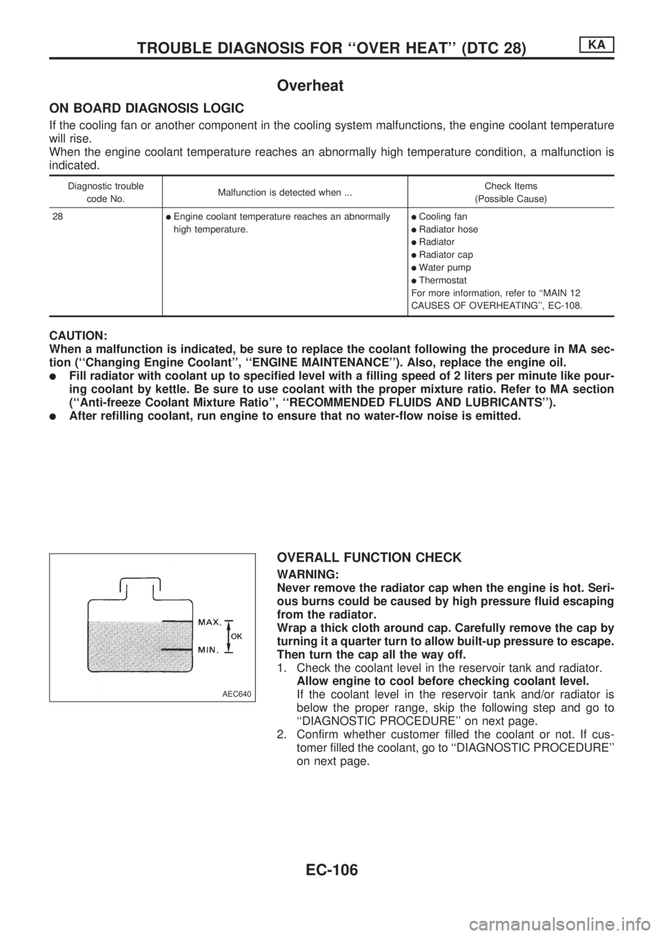
OVERALL FUNCTION CHECK
WARNING:
Never remove the radiator cap when the engine is hot. Seri-
ous burns could be caused by high pressure fluid escaping
from the radiator.
Wrap a thick cloth around cap. Carefully remove the cap by
turning it a quarter turn to allow built-up pressure to escape.
Then turn the cap all the way off.
1. Check the coolant level in the reservoir tank and radiator.
Allow engine to cool before checking coolant level.
If the coolant level in the reservoir tank and/or radiator is
below the proper range, skip the following step and go to
``DIAGNOSTIC PROCEDURE'' on next page.
2. Confirm whether customer filled the coolant or not. If cus-
tomer filled the coolant, go to ``DIAGNOSTIC PROCEDURE''
on next page.
AEC640
TROUBLE DIAGNOSIS FOR ``OVER HEAT'' (DTC 28)KA
EC-106
Page 808 of 1659
lAfter disconnecting vacuum or air hoses, attach a tag to
indicate the proper connection.
lUse only the fluids and lubricants specified in this manual.
lUse approved bonding agent, sealants or their equivalents
when required.
lUse tools and recommended special tools where specified
for safe and efficient service repairs.
lWhen repairing the fuel, oil, water, vacuum or exhaust
systems, check all affected lines for leaks.
lDispose of drained oil or the solvent used for cleaning parts
in an appropriate manner.
WARNING:
To prevent ECM from storing the diagnostic trouble codes,
do not carelessly disconnect the harness connectors which
are related to the ECCS system and TCM (Transmission
Control Module) system. The connectors should be discon-
nected only when working according to the WORK FLOW of
TROUBLE DIAGNOSES in EC section.
Precautions for Multiport Fuel Injection
System or ECCS Engine
lBefore connecting or disconnecting any harness connector
for the multiport fuel injection system or ECM (Engine Con-
trol Module):
Turn ignition switch to ``OFF'' position.
Disconnect negative battery terminal.
Otherwise, there may be damage to ECM.
lBefore disconnecting pressurized fuel line from fuel pump to
injectors, be sure to release fuel pressure.
lBe careful not to jar components such as ECM and mass air
flow sensor.
Precautions for Three Way Catalyst
(If so equipped)
If a large amount of unburned fuel flows into the catalyst, the
catalyst temperature will be excessively high. To prevent this,
follow the instructions below:
lUse unleaded gasoline only. Leaded gasoline will seriously
damage the three way catalyst.
lWhen checking for ignition spark or measuring engine
compression, make tests quickly and only when necessary.
lDo not run engine when the fuel tank level is low, otherwise
the engine may misfire causing damage to the catalyst.
Do not place the vehicle on flammable material. Keep flammable
material off the exhaust pipe and the three way catalyst.
Precautions for Engine Oils
Prolonged and repeated contact with used engine oil may cause
skin cancer. Try to avoid direct skin contact with used oil.
SGI787
PRECAUTIONS
General Precautions (Cont'd)
GI-4
Page 809 of 1659
If skin contact is made, wash thoroughly with soap or hand
cleaner as soon as possible.
HEALTH PROTECTION PRECAUTIONS
lAvoid prolonged and repeated contact with oils, particularly
used engine oils.
lWear protective clothing, including impervious gloves where
practicable.
lDo not put oily rags in pockets.
lAvoid contaminating clothes, particularly underpants, with oil.
lHeavily soiled clothing and oil-impregnated footwear should
not be worn. Overalls must be cleaned regularly.
lFirst Aid treatment should be obtained immediately for open
cuts and wounds.
lUse barrier creams, applying them before each work period,
to help the removal of oil from the skin.
lWash with soap and water to ensure all oil is removed (skin
cleansers and nail brushes will help). Preparations contain-
ing lanolin replace the natural skin oils which have been
removed.
lDo not use gasoline, kerosine, diesel fuel, gas oil, thinners
or solvents for cleaning skin.
lIf skin disorders develop, obtain medical advice without
delay.
lWhere practicable, degrease components prior to handling.
lWhere there is a risk of eye contact, eye protection should
be worn, for example, chemical goggles or face shields; in
addition an eye wash facility should be provided.
ENVIRONMENTAL PROTECTION PRECAUTIONS
Burning used engine oil in small space heaters or boilers can be
recommended only for units of approved design. The heating
system must meet the requirements of HM Inspectorate of Pol-
lution for small burners of less than 0.4 MW. If in doubt check
with the appropriate local authority and/or manufacturer of the
approved appliance.
Dispose of used oil and used oil filters through authorized waste
disposal contractors to licensed waste disposal sites, or to the
waste oil reclamation trade. If in doubt, contact the local author-
ity for advice on disposal facilities.
It is illegal to pour used oil on to the ground, down sewers or
drains, or into water courses.
The regulations concerning the pollution of the environment
will vary from country to country.
Precautions for Fuel
GASOLINE ENGINE:
Three way catalyst equipped models ... unleaded gasoline of at
least 91 octane (RON)
CAUTION:
Do not use leaded gasoline. Using leaded gasoline will dam-
age the three way catalyst.
Except for the above models ... unleaded or leaded gasoline of
above 88 octane (RON)
Use unleaded fuel if instructed on the fuel filler lid.
PRECAUTIONS
Precautions for Engine Oils (Cont'd)
GI-5
Page 812 of 1659
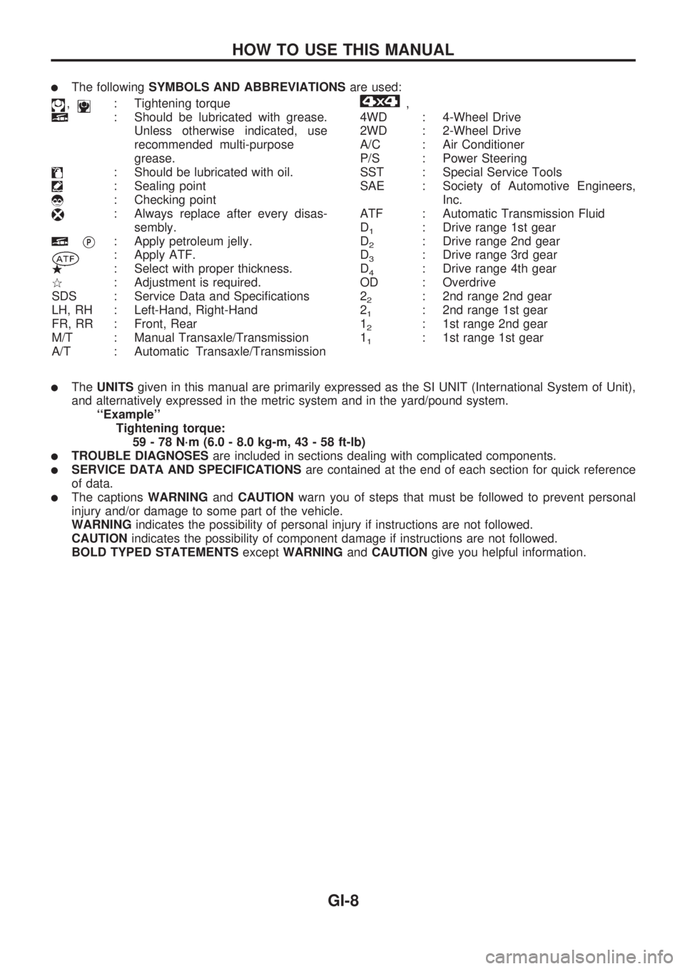
lThe followingSYMBOLS AND ABBREVIATIONSare used:
,: Tightening torque
: Should be lubricated with grease.
Unless otherwise indicated, use
recommended multi-purpose
grease.
: Should be lubricated with oil.
: Sealing point
: Checking point
: Always replace after every disas-
sembly.
VP: Apply petroleum jelly.
: Apply ATF.
.: Select with proper thickness.
>: Adjustment is required.
SDS : Service Data and Specifications
LH, RH : Left-Hand, Right-Hand
FR, RR : Front, Rear
M/T : Manual Transaxle/Transmission
A/T : Automatic Transaxle/Transmission
,
4WD : 4-Wheel Drive
2WD : 2-Wheel Drive
A/C : Air Conditioner
P/S : Power Steering
SST : Special Service Tools
SAE : Society of Automotive Engineers,
Inc.
ATF : Automatic Transmission Fluid
D
1: Drive range 1st gear
D
2: Drive range 2nd gear
D
3: Drive range 3rd gear
D
4: Drive range 4th gear
OD : Overdrive
2
2: 2nd range 2nd gear
2
1: 2nd range 1st gear
1
2: 1st range 2nd gear
1
1: 1st range 1st gear
lTheUNITSgiven in this manual are primarily expressed as the SI UNIT (International System of Unit),
and alternatively expressed in the metric system and in the yard/pound system.
``Example''
Tightening torque:
59 - 78 N´m (6.0 - 8.0 kg-m, 43 - 58 ft-lb)
lTROUBLE DIAGNOSESare included in sections dealing with complicated components.
lSERVICE DATA AND SPECIFICATIONSare contained at the end of each section for quick reference
of data.
lThe captionsWARNINGandCAUTIONwarn you of steps that must be followed to prevent personal
injury and/or damage to some part of the vehicle.
WARNINGindicates the possibility of personal injury if instructions are not followed.
CAUTIONindicates the possibility of component damage if instructions are not followed.
BOLD TYPED STATEMENTSexceptWARNINGandCAUTIONgive you helpful information.
HOW TO USE THIS MANUAL
GI-8
Page 881 of 1659
Precautions for Service Equipment
RECOVERY/RECYCLING EQUIPMENT
Be certain to follow the manufacturers instructions for machine
operation and machine maintenance. Never introduce any refrig-
erant other than that specified into the machine.
ELECTRONIC LEAK DETECTOR
Be certain to follow the manufacturer's instructions for tester
operation and tester maintenance.
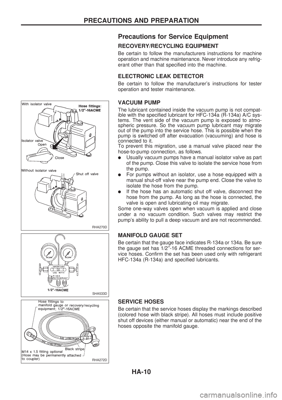
VACUUM PUMP
The lubricant contained inside the vacuum pump is not compat-
ible with the specified lubricant for HFC-134a (R-134a) A/C sys-
tems. The vent side of the vacuum pump is exposed to atmo-
spheric pressure. So the vacuum pump lubricant may migrate
out of the pump into the service hose. This is possible when the
pump is switched off after evacuation (vacuuming) and hose is
connected to it.
To prevent this migration, use a manual valve placed near the
hose-to-pump connection, as follows.
lUsually vacuum pumps have a manual isolator valve as part
of the pump. Close this valve to isolate the service hose from
the pump.
lFor pumps without an isolator, use a hose equipped with a
manual shut-off valve near the pump end. Close the valve to
isolate the hose from the pump.
lIf the hose has an automatic shut off valve, disconnect the
hose from the pump. As long as the hose is connected, the
valve is open and lubricating oil may migrate.
Some one-way valves open when vacuum is applied and close
under a no vacuum condition. Such valves may restrict the
pump's ability to pull a deep vacuum and are not recommended.
MANIFOLD GAUGE SET
Be certain that the gauge face indicates R-134a or 134a. Be sure
the gauge set has 1/2²-16 ACME threaded connections for ser-
vice hoses. Confirm the set has been used only with refrigerant
HFC-134a (R-134a) and specified lubricants.
SERVICE HOSES
Be certain that the service hoses display the markings described
(colored hose with black stripe). All hoses must include positive
shut off devices (either manual or automatic) near the end of the
hoses opposite the manifold gauge.
RHA270D
SHA533D
RHA272D
PRECAUTIONS AND PREPARATION
HA-10
Page 972 of 1659
MAINTENANCE
SECTION
MA
CONTENTS
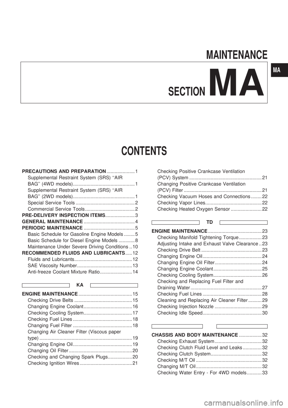
PRECAUTIONS AND PREPARATION..................... 1
Supplemental Restraint System (SRS) ``AIR
BAG'' (4WD models).............................................. 1
Supplemental Restraint System (SRS) ``AIR
BAG'' (2WD models).............................................. 1
Special Service Tools ............................................ 2
Commercial Service Tools ..................................... 2
PRE-DELIVERY INSPECTION ITEMS...................... 3
GENERAL MAINTENANCE...................................... 4
PERIODIC MAINTENANCE...................................... 5
Basic Schedule for Gasoline Engine Models ........ 5
Basic Schedule for Diesel Engine Models ............ 8
Maintenance Under Severe Driving Conditions .. 10
RECOMMENDED FLUIDS AND LUBRICANTS..... 12
Fluids and Lubricants........................................... 12
SAE Viscosity Number......................................... 13
Anti-freeze Coolant Mixture Ratio........................ 14
KA
ENGINE MAINTENANCE........................................ 15
Checking Drive Belts ........................................... 15
Changing Engine Coolant .................................... 16
Checking Cooling System.................................... 17
Checking Fuel Lines ............................................ 18
Changing Fuel Filter ............................................ 18
Changing Air Cleaner Filter (Viscous paper
type) ..................................................................... 19
Changing Engine Oil ............................................ 19
Changing Oil Filter ............................................... 20
Checking and Changing Spark Plugs.................. 20
Checking Ignition Wires ....................................... 21Checking Positive Crankcase Ventilation
(PCV) System ...................................................... 21
Changing Positive Crankcase Ventilation
(PCV) Filter .......................................................... 21
Checking Vacuum Hoses and Connections ........ 22
Checking Vapor Lines.......................................... 22
Checking Heated Oxygen Sensor ....................... 22
TD
ENGINE MAINTENANCE........................................ 23
Checking Manifold Tightening Torque ................. 23
Adjusting Intake and Exhaust Valve Clearance .. 23
Checking Drive Belt ............................................. 23
Changing Engine Oil ............................................ 24
Changing Engine Oil Filter................................... 24
Changing Engine Coolant .................................... 25
Checking Cooling System.................................... 26
Checking and Replacing Fuel Filter and
Draining Water ..................................................... 27
Checking Fuel Lines ............................................ 28
Cleaning and Replacing Air Cleaner Filter .......... 29
Checking Injection Nozzle ................................... 29
Checking Idle Speed............................................ 30
CHASSIS AND BODY MAINTENANCE................. 32
Checking Exhaust System ................................... 32
Checking Clutch Fluid Level and Leaks .............. 32
Checking Clutch System...................................... 32
Checking M/T Oil ................................................. 32
Changing M/T Oil ................................................. 32
Checking Water Entry - For 4WD models ........... 33
MA
Page 976 of 1659
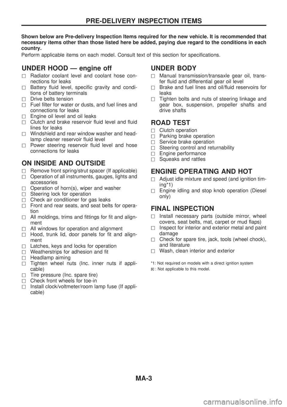
Shown below are Pre-delivery Inspection Items required for the new vehicle. It is recommended that
necessary items other than those listed here be added, paying due regard to the conditions in each
country.
Perform applicable items on each model. Consult text of this section for specifications.
UNDER HOOD Ð engine off
hRadiator coolant level and coolant hose con-
nections for leaks
hBattery fluid level, specific gravity and condi-
tions of battery terminals
hDrive belts tension
hFuel filter for water or dusts, and fuel lines and
connections for leaks
hEngine oil level and oil leaks
hClutch and brake reservoir fluid level and fluid
lines for leaks
hWindshield and rear window washer and head-
lamp cleaner reservoir fluid level
hPower steering reservoir fluid level and hose
connections for leaks
ON INSIDE AND OUTSIDE
hRemove front spring/strut spacer (If applicable)
hOperation of all instruments, gauges, lights and
accessories
hOperation of horn(s), wiper and washer
hSteering lock for operation
hCheck air conditioner for gas leaks
hFront and rear seats, and seat belts for opera-
tion
hAll moldings, trims and fittings for fit and align-
ment
hAll windows for operation and alignment
hHood, trunk lid, door panels for fit and align-
ment
hLatches, keys and locks for operation
hWeatherstrips for adhesion and fit
hHeadlamp aiming
hTighten wheel nuts (Inc. inner nuts if appli-
cable)
hTire pressure (Inc. spare tire)
hCheck front wheels for toe-in
hInstall clock/voltmeter/room lamp fuse (If appli-
cable)
UNDER BODY
hManual transmission/transaxle gear oil, trans-
fer fluid and differential gear oil level
hBrake and fuel lines and oil/fluid reservoirs for
leaks
hTighten bolts and nuts of steering linkage and
gear box, suspension, propeller shafts and
drive shafts
ROAD TEST
hClutch operation
hParking brake operation
hService brake operation
hSteering control and returnability
hEngine performance
hSqueaks and rattles
ENGINE OPERATING AND HOT
hAdjust idle mixture and speed (and ignition tim-
ing*1)
hEngine idling and stop knob operation (Diesel
only)
FINAL INSPECTION
hInstall necessary parts (outside mirror, wheel
covers, seat belts, mat, carpet or mud flaps)
hInspect for interior and exterior metal and paint
damage
hCheck for spare tire, jack, tools (wheel chock),
and literature
hWash, clean interior and exterior
*1: Not required on models with a direct ignition system
h
X: Not applicable to this model.
PRE-DELIVERY INSPECTION ITEMS
MA-3