Page 1585 of 1659
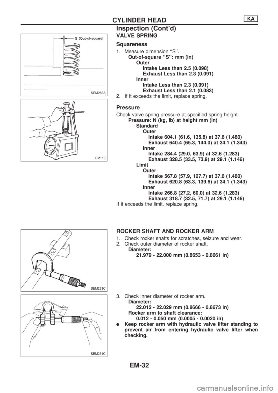
VALVE SPRING
Squareness
1. Measure dimension ``S''.
Out-of-square ``S'': mm (in)
Outer
Intake Less than 2.5 (0.098)
Exhaust Less than 2.3 (0.091)
Inner
Intake Less than 2.3 (0.091)
Exhaust Less than 2.1 (0.083)
2. If it exceeds the limit, replace spring.
Pressure
Check valve spring pressure at specified spring height.
Pressure: N (kg, lb) at height mm (in)
Standard
Outer
Intake 604.1 (61.6, 135.8) at 37.6 (1.480)
Exhaust 640.4 (65.3, 144.0) at 34.1 (1.343)
Inner
Intake 284.4 (29.0, 63.9) at 32.6 (1.283)
Exhaust 328.5 (33.5, 73.9) at 29.1 (1.146)
Limit
Outer
Intake 567.8 (57.9, 127.7) at 37.6 (1.480)
Exhaust 620.8 (63.3, 139.6) at 34.1 (1.343)
Inner
Intake 266.8 (27.2, 60.0) at 32.6 (1.283)
Exhaust 318.7 (32.5, 71.7) at 29.1 (1.146)
If it exceeds the limit, replace spring.
ROCKER SHAFT AND ROCKER ARM
1. Check rocker shafts for scratches, seizure and wear.
2. Check outer diameter of rocker shaft.
Diameter:
21.979 - 22.000 mm (0.8653 - 0.8661 in)
3. Check inner diameter of rocker arm.
Diameter:
22.012 - 22.029 mm (0.8666 - 0.8673 in)
Rocker arm to shaft clearance:
0.012 - 0.050 mm (0.0005 - 0.0020 in)
lKeep rocker arm with hydraulic valve lifter standing to
prevent air from entering hydraulic valve lifter when
checking.
SEM288A
EM113
SEM233C
SEM234C
CYLINDER HEADKA
Inspection (Cont'd)
EM-32
Page 1594 of 1659
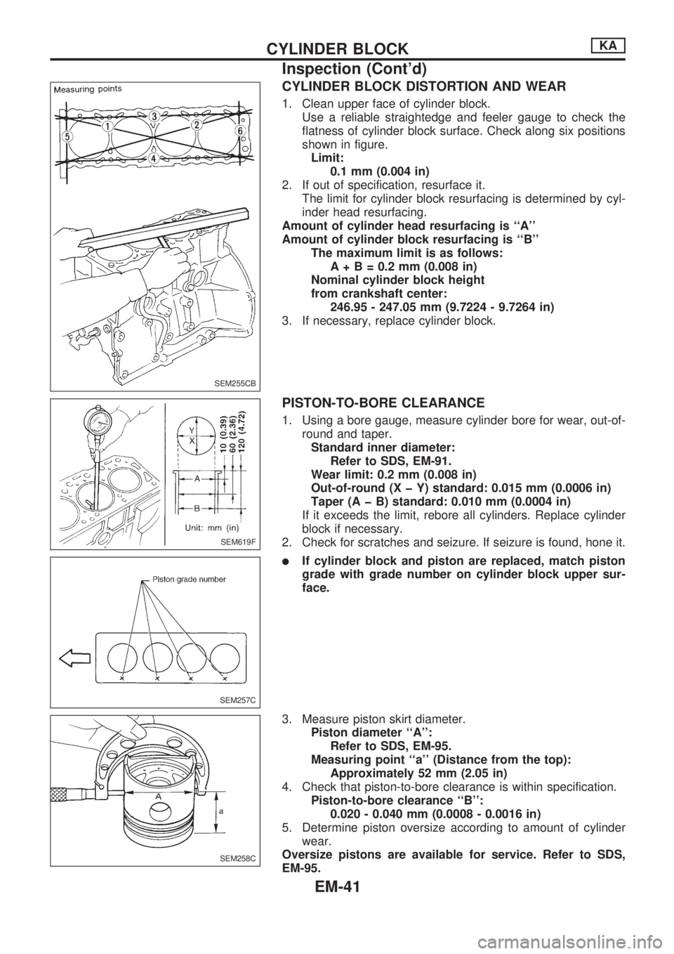
CYLINDER BLOCK DISTORTION AND WEAR
1. Clean upper face of cylinder block.
Use a reliable straightedge and feeler gauge to check the
flatness of cylinder block surface. Check along six positions
shown in figure.
Limit:
0.1 mm (0.004 in)
2. If out of specification, resurface it.
The limit for cylinder block resurfacing is determined by cyl-
inder head resurfacing.
Amount of cylinder head resurfacing is ``A''
Amount of cylinder block resurfacing is ``B''
The maximum limit is as follows:
A+B=0.2mm(0.008 in)
Nominal cylinder block height
from crankshaft center:
246.95 - 247.05 mm (9.7224 - 9.7264 in)
3. If necessary, replace cylinder block.
PISTON-TO-BORE CLEARANCE
1. Using a bore gauge, measure cylinder bore for wear, out-of-
round and taper.
Standard inner diameter:
Refer to SDS, EM-91.
Wear limit: 0.2 mm (0.008 in)
Out-of-round (X þ Y) standard: 0.015 mm (0.0006 in)
Taper (A þ B) standard: 0.010 mm (0.0004 in)
If it exceeds the limit, rebore all cylinders. Replace cylinder
block if necessary.
2. Check for scratches and seizure. If seizure is found, hone it.
lIf cylinder block and piston are replaced, match piston
grade with grade number on cylinder block upper sur-
face.
3. Measure piston skirt diameter.
Piston diameter ``A'':
Refer to SDS, EM-95.
Measuring point ``a'' (Distance from the top):
Approximately 52 mm (2.05 in)
4. Check that piston-to-bore clearance is within specification.
Piston-to-bore clearance ``B'':
0.020 - 0.040 mm (0.0008 - 0.0016 in)
5. Determine piston oversize according to amount of cylinder
wear.
Oversize pistons are available for service. Refer to SDS,
EM-95.
SEM255CB
SEM619F
SEM257C
SEM258C
CYLINDER BLOCKKA
Inspection (Cont'd)
EM-41
Page 1609 of 1659
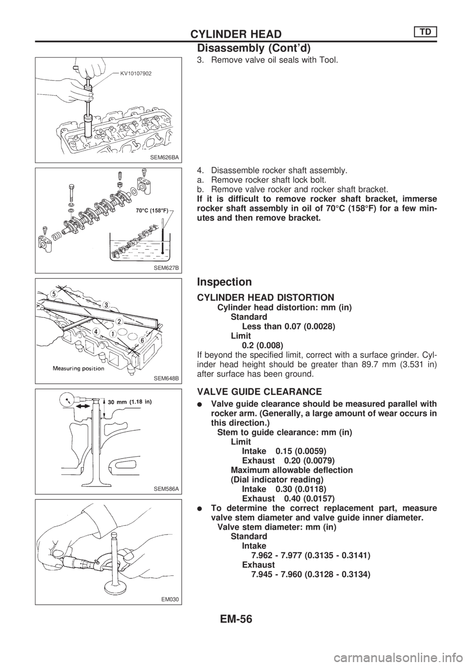
3. Remove valve oil seals with Tool.
4. Disassemble rocker shaft assembly.
a. Remove rocker shaft lock bolt.
b. Remove valve rocker and rocker shaft bracket.
If it is difficult to remove rocker shaft bracket, immerse
rocker shaft assembly in oil of 70ÉC (158ÉF) for a few min-
utes and then remove bracket.
Inspection
CYLINDER HEAD DISTORTION
Cylinder head distortion: mm (in)
Standard
Less than 0.07 (0.0028)
Limit
0.2 (0.008)
If beyond the specified limit, correct with a surface grinder. Cyl-
inder head height should be greater than 89.7 mm (3.531 in)
after surface has been ground.
VALVE GUIDE CLEARANCE
lValve guide clearance should be measured parallel with
rocker arm. (Generally, a large amount of wear occurs in
this direction.)
Stem to guide clearance: mm (in)
Limit
Intake 0.15 (0.0059)
Exhaust 0.20 (0.0079)
Maximum allowable deflection
(Dial indicator reading)
Intake 0.30 (0.0118)
Exhaust 0.40 (0.0157)
lTo determine the correct replacement part, measure
valve stem diameter and valve guide inner diameter.
Valve stem diameter: mm (in)
Standard
Intake
7.962 - 7.977 (0.3135 - 0.3141)
Exhaust
7.945 - 7.960 (0.3128 - 0.3134)
SEM626BA
SEM627B
SEM648B
SEM586A
EM030
CYLINDER HEADTD
Disassembly (Cont'd)
EM-56
Page 1616 of 1659
Installation
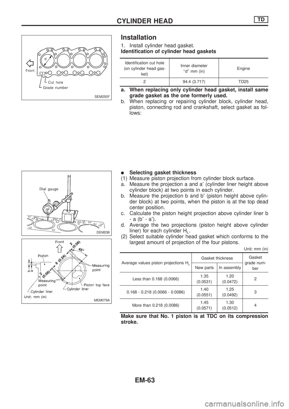
1. Install cylinder head gasket.
Identification of cylinder head gaskets
Identification cut hole
(on cylinder head gas-
ket)Inner diameter
``d'' mm (in)Engine
2 94.4 (3.717) TD25
a. When replacing only cylinder head gasket, install same
grade gasket as the one formerly used.
b. When replacing or repairing cylinder block, cylinder head,
piston, connecting rod and crankshaft, select gasket as fol-
lows:
lSelecting gasket thickness
(1) Measure piston projection from cylinder block surface.
a. Measure the projection a and a¢(cylinder liner height above
cylinder block) at two points in each cylinder.
b. Measure the projection b and b¢(piston height above cylin-
der block) at two points, when the piston is at the top dead
center position.
c. Calculate the piston height projection above cylinder liner b
-a(b¢-a¢).
d. Average the two projections (piston height above cylinder
liner) for each cylinder H
L.
(2) Select suitable cylinder head gasket which conforms to the
largest amount of projection of the four pistons.
Unit: mm (in)
Average values piston projections HL
Gasket thicknessGasket
grade num-
ber New parts In assembly
Less than 0.168 (0.0066)1.35
(0.0531)1.20
(0.0472)2
0.168 - 0.218 (0.0066 - 0.0086)1.40
(0.0551)1.25
(0.0492)3
More than 0.218 (0.0086)1.45
(0.0571)1.30
(0.0512)4
Make sure that No. 1 piston is at TDC on its compression
stroke.
SEM250F
.
DEM036
MEM079A
CYLINDER HEADTD
EM-63
Page 1639 of 1659
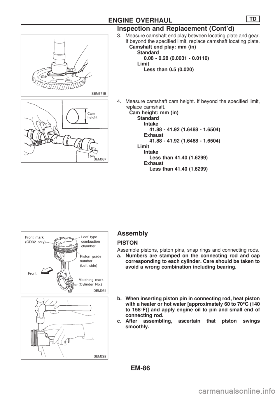
3. Measure camshaft end play between locating plate and gear.
If beyond the specified limit, replace camshaft locating plate.
Camshaft end play: mm (in)
Standard
0.08 - 0.28 (0.0031 - 0.0110)
Limit
Less than 0.5 (0.020)
4. Measure camshaft cam height. If beyond the specified limit,
replace camshaft.
Cam height: mm (in)
Standard
Intake
41.88 - 41.92 (1.6488 - 1.6504)
Exhaust
41.88 - 41.92 (1.6488 - 1.6504)
Limit
Intake
Less than 41.40 (1.6299)
Exhaust
Less than 41.40 (1.6299)
Assembly
PISTON
Assemble pistons, piston pins, snap rings and connecting rods.
a. Numbers are stamped on the connecting rod and cap
corresponding to each cylinder. Care should be taken to
avoid a wrong combination including bearing.
b. When inserting piston pin in connecting rod, heat piston
with a heater or hot water [approximately 60 to 70ÉC (140
to 158ÉF)] and apply engine oil to pin and small end of
connecting rod.
c. After assembling, ascertain that piston swings
smoothly.
SEM671B
SEM037
DEM054
SEM292
ENGINE OVERHAULTD
Inspection and Replacement (Cont'd)
EM-86
Page 1644 of 1659
General Specifications
Cylinder arrangement 4, in-line
Displacement cm
3(cu in) 2,389 (145.78)
Bore x stroke mm (in) 89 x 96 (3.50 x 3.78)
Valve arrangement OHC
Firing order 1-3-4-2
Number of piston rings
Compression 2
Oil 1
Number of main bearings 5
Compression ratio 8.6
Unit: kPa (bar, kg/cm2, psi)/rpm
Compression pressure
Standard 1,324 (13.24, 13.5, 192)/300
Minimum 981 (9.8, 10, 142)/300
Differential limit between cylin-
ders98 (0.98, 1.0, 14)/300
Inspection and Adjustment
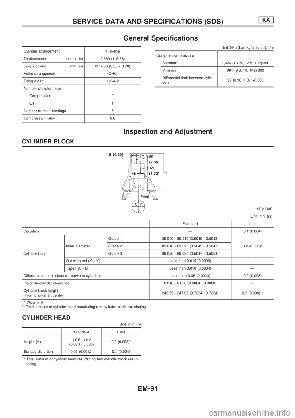
CYLINDER BLOCK
SEM618F
Unit: mm (in)
Standard Limit
DistortionÐ 0.1 (0.004)
Cylinder boreInner diameterGrade 1 89.000 - 89.010 (3.5039 - 3.5043)
0.2 (0.008)* Grade 2 89.010 - 89.020 (3.5043 - 3.5047)
Grade 3 89.020 - 89.030 (3.5047 - 3.5051)
Out-of-round (X þ Y) Less than 0.015 (0.0006) Ð
Taper (A þ B) Less than 0.010 (0.0004) Ð
Difference in inner diameter between cylinders Less than 0.05 (0.0020) 0.2 (0.008)
Piston-to-cylinder clearance 0.010 - 0.020 (0.0004 - 0.0008) Ð
Cylinder block height
(From crankshaft center)246.95 - 247.05 (9.7224 - 9.7264) 0.2 (0.008)**
* Wear limit
** Total amount of cylinder head resurfacing and cylinder block resurfacing
CYLINDER HEAD
Unit: mm (in)
Standard Limit
Height (H)98.8 - 99.0
(3.890 - 3.898)0.2 (0.008)*
Surface distortion 0.03 (0.0012) 0.1 (0.004)
* Total amount of cylinder head resurfacing and cylinder block resur-
facing
SERVICE DATA AND SPECIFICATIONS (SDS)KA
EM-91
Page 1646 of 1659
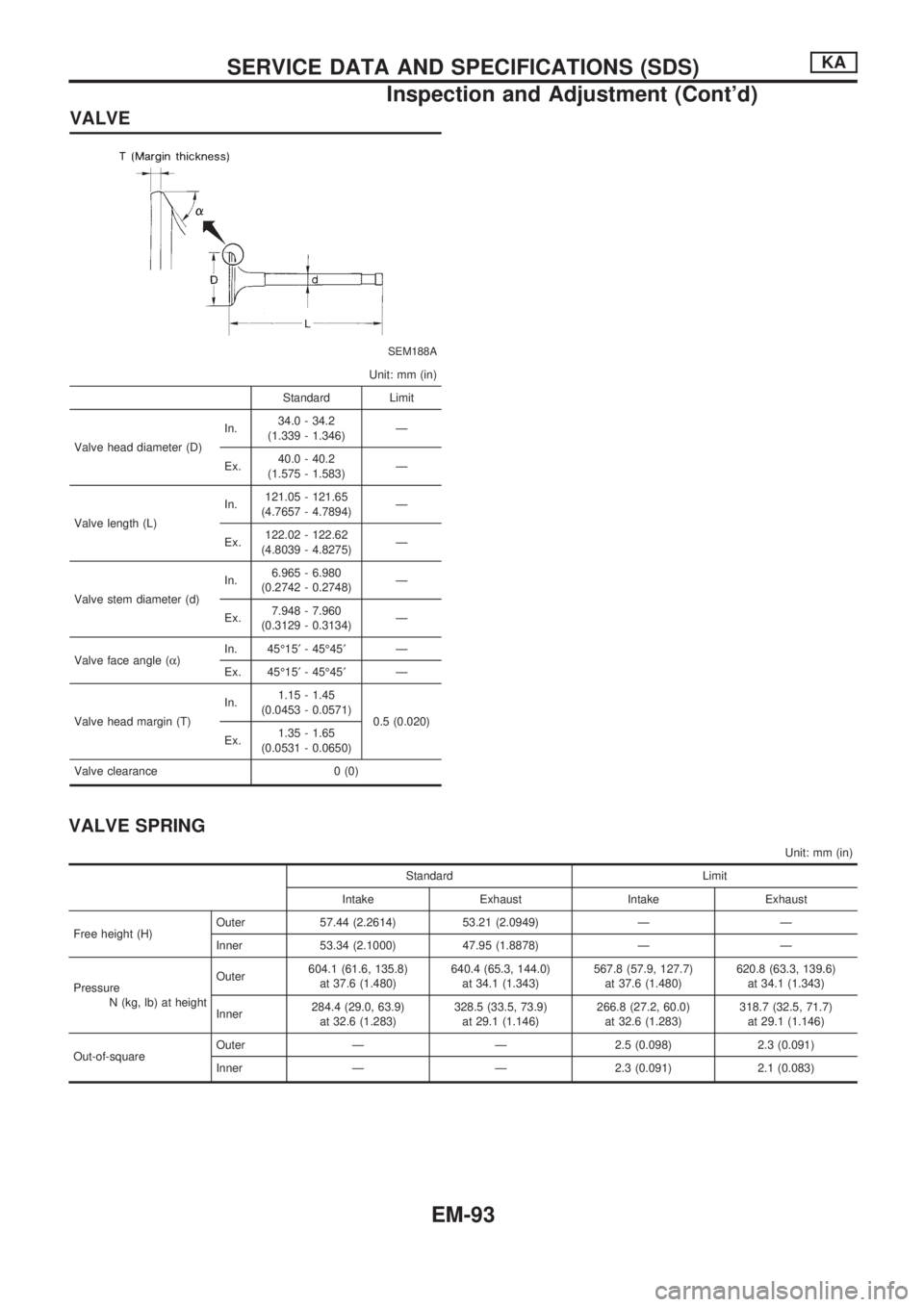
VALVE
SEM188A
Unit: mm (in)
Standard Limit
Valve head diameter (D)In.34.0 - 34.2
(1.339 - 1.346)Ð
Ex.40.0 - 40.2
(1.575 - 1.583)Ð
Valve length (L)In.121.05 - 121.65
(4.7657 - 4.7894)Ð
Ex.122.02 - 122.62
(4.8039 - 4.8275)Ð
Valve stem diameter (d)In.6.965 - 6.980
(0.2742 - 0.2748)Ð
Ex.7.948 - 7.960
(0.3129 - 0.3134)Ð
Valve face angle (a)In. 45É15¢- 45É45¢Ð
Ex. 45É15¢- 45É45¢Ð
Valve head margin (T)In.1.15 - 1.45
(0.0453 - 0.0571)
0.5 (0.020)
Ex.1.35 - 1.65
(0.0531 - 0.0650)
Valve clearance 0 (0)
VALVE SPRING
Unit: mm (in)
Standard Limit
Intake Exhaust Intake Exhaust
Free height (H)Outer 57.44 (2.2614) 53.21 (2.0949) Ð Ð
Inner 53.34 (2.1000) 47.95 (1.8878) Ð Ð
Pressure
N (kg, lb) at heightOuter604.1 (61.6, 135.8)
at 37.6 (1.480)640.4 (65.3, 144.0)
at 34.1 (1.343)567.8 (57.9, 127.7)
at 37.6 (1.480)620.8 (63.3, 139.6)
at 34.1 (1.343)
Inner284.4 (29.0, 63.9)
at 32.6 (1.283)328.5 (33.5, 73.9)
at 29.1 (1.146)266.8 (27.2, 60.0)
at 32.6 (1.283)318.7 (32.5, 71.7)
at 29.1 (1.146)
Out-of-squareOuter Ð Ð 2.5 (0.098) 2.3 (0.091)
Inner Ð Ð 2.3 (0.091) 2.1 (0.083)
SERVICE DATA AND SPECIFICATIONS (SDS)KA
Inspection and Adjustment (Cont'd)
EM-93
Page 1647 of 1659
CAMSHAFT AND CAMSHAFT BEARING
SEM568A
EM120
Unit: mm (in)
Standard Limit
Cam height (A) 44.43 - 44.58 (1.7492 - 1.7551) Ð
Valve lift (h) 9.7 (0.382) Ð
Wear limit of cam height Ð 0.2 (0.008)
Camshaft journal to bearing clearance 0.045 - 0.090 (0.0018 - 0.0035) 0.12 (0.0047)
Inner diameter of camshaft bearing 33.000 - 33.025 (1.2992 - 1.3002) Ð
Outer diameter of camshaft journal (D) 32.935 - 32.955 (1.2967 - 1.2974) Ð
Camshaft runout 0 - 0.02 (0 - 0.0008) Ð
Camshaft end play 0.07 - 0.15 (0.0028 - 0.0059) 0.2 (0.008)
Valve timing (Degree on crankshaft)a 232 Ð
b 232 Ð
cþ5 Ð
d57 Ð
e11 Ð
f41 Ð
ROCKER ARM AND ROCKER SHAFT
Unit: mm (in)
Rocker arm to shaft clearance 0.012 - 0.050 (0.0005 - 0.0020)
Rocker shaft diameter21.979 - 22.000
(0.8653 - 0.8661)
Rocker arm rocker shaft hole
diameter22.012 - 22.029
(0.8666 - 0.8673)
SERVICE DATA AND SPECIFICATIONS (SDS)KA
Inspection and Adjustment (Cont'd)
EM-94