Page 739 of 1659
CAMSHAFT AND CAMSHAFT BEARING
SEM568A
EM120
Unit: mm (in)
Standard Limit
Cam height (A) 44.43 - 44.58 (1.7492 - 1.7551) Ð
Valve lift (h) 9.7 (0.382) Ð
Wear limit of cam height Ð 0.2 (0.008)
Camshaft journal to bearing clearance 0.045 - 0.090 (0.0018 - 0.0035) 0.12 (0.0047)
Inner diameter of camshaft bearing 33.000 - 33.025 (1.2992 - 1.3002) Ð
Outer diameter of camshaft journal (D) 32.935 - 32.955 (1.2967 - 1.2974) Ð
Camshaft runout 0 - 0.02 (0 - 0.0008) Ð
Camshaft end play 0.07 - 0.15 (0.0028 - 0.0059) 0.2 (0.008)
Valve timing (Degree on crankshaft)a 232 Ð
b 232 Ð
cþ5 Ð
d57 Ð
e11 Ð
f41 Ð
ROCKER ARM AND ROCKER SHAFT
Unit: mm (in)
Rocker arm to shaft clearance 0.012 - 0.050 (0.0005 - 0.0020)
Rocker shaft diameter21.979 - 22.000
(0.8653 - 0.8661)
Rocker arm rocker shaft hole
diameter22.012 - 22.029
(0.8666 - 0.8673)
SERVICE DATA AND SPECIFICATIONS (SDS)KA
Inspection and Adjustment (Cont'd)
EM-94
Page 743 of 1659

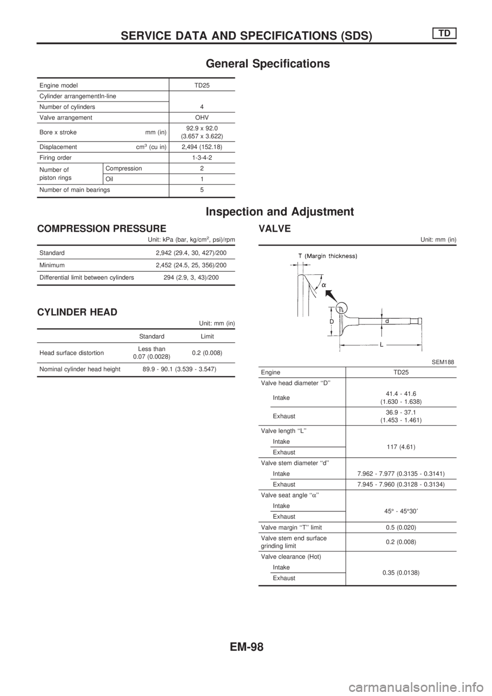
General Specifications
Engine model TD25
Cylinder arrangementIn-line
Number of cylinders 4
Valve arrangement OHV
Bore x stroke mm (in)92.9 x 92.0
(3.657 x 3.622)
Displacement cm
3(cu in) 2,494 (152.18)
Firing order 1-3-4-2
Number of
piston ringsCompression 2
Oil 1
Number of main bearings 5
Inspection and Adjustment
COMPRESSION PRESSURE
Unit: kPa (bar, kg/cm2, psi)/rpm
Standard 2,942 (29.4, 30, 427)/200
Minimum 2,452 (24.5, 25, 356)/200
Differential limit between cylinders 294 (2.9, 3, 43)/200
CYLINDER HEAD
Unit: mm (in)
Standard Limit
Head surface distortionLess than
0.07 (0.0028)0.2 (0.008)
Nominal cylinder head height 89.9 - 90.1 (3.539 - 3.547)
VALVE
Unit: mm (in)
SEM188
Engine TD25
Valve head diameter ``D''
Intake41.4 - 41.6
(1.630 - 1.638)
Exhaust36.9 - 37.1
(1.453 - 1.461)
Valve length ``L''
Intake
117 (4.61)
Exhaust
Valve stem diameter ``d''
Intake 7.962 - 7.977 (0.3135 - 0.3141)
Exhaust 7.945 - 7.960 (0.3128 - 0.3134)
Valve seat angle ``a''
Intake
45É - 45É30¢
Exhaust
Valve margin ``T'' limit 0.5 (0.020)
Valve stem end surface
grinding limit0.2 (0.008)
Valve clearance (Hot)
Intake
0.35 (0.0138)
Exhaust
SERVICE DATA AND SPECIFICATIONS (SDS)TD
EM-98
Page 744 of 1659

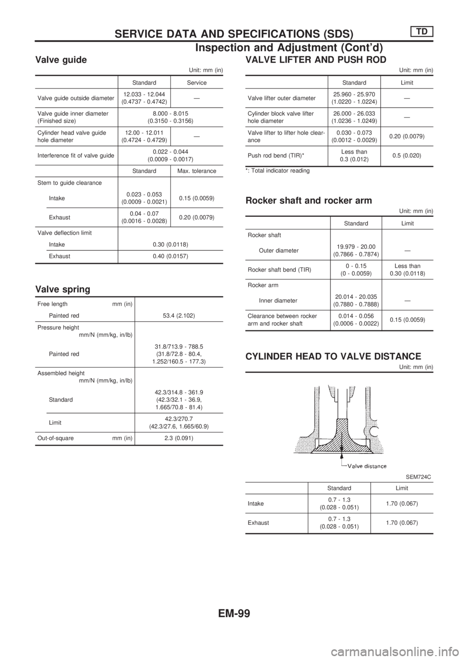
Valve guide
Unit: mm (in)
Standard Service
Valve guide outside diameter12.033 - 12.044
(0.4737 - 0.4742)Ð
Valve guide inner diameter
(Finished size)8.000 - 8.015
(0.3150 - 0.3156)
Cylinder head valve guide
hole diameter12.00 - 12.011
(0.4724 - 0.4729)Ð
Interference fit of valve guide0.022 - 0.044
(0.0009 - 0.0017)
Standard Max. tolerance
Stem to guide clearance
Intake0.023 - 0.053
(0.0009 - 0.0021)0.15 (0.0059)
Exhaust0.04 - 0.07
(0.0016 - 0.0028)0.20 (0.0079)
Valve deflection limit
Intake 0.30 (0.0118)
Exhaust 0.40 (0.0157)
Valve spring
Free length mm (in)
Painted red 53.4 (2.102)
Pressure height
mm/N (mm/kg, in/lb)
Painted red31.8/713.9 - 788.5
(31.8/72.8 - 80.4,
1.252/160.5 - 177.3)
Assembled height
mm/N (mm/kg, in/lb)
Standard42.3/314.8 - 361.9
(42.3/32.1 - 36.9,
1.665/70.8 - 81.4)
Limit42.3/270.7
(42.3/27.6, 1.665/60.9)
Out-of-square mm (in) 2.3 (0.091)
VALVE LIFTER AND PUSH ROD
Unit: mm (in)
Standard Limit
Valve lifter outer diameter25.960 - 25.970
(1.0220 - 1.0224)Ð
Cylinder block valve lifter
hole diameter26.000 - 26.033
(1.0236 - 1.0249)Ð
Valve lifter to lifter hole clear-
ance0.030 - 0.073
(0.0012 - 0.0029)0.20 (0.0079)
Push rod bend (TIR)*Less than
0.3 (0.012)0.5 (0.020)
*: Total indicator reading
Rocker shaft and rocker arm
Unit: mm (in)
Standard Limit
Rocker shaft
Outer diameter19.979 - 20.00
(0.7866 - 0.7874)Ð
Rocker shaft bend (TIR)0 - 0.15
(0 - 0.0059)Less than
0.30 (0.0118)
Rocker arm
Inner diameter20.014 - 20.035
(0.7880 - 0.7888)Ð
Clearance between rocker
arm and rocker shaft0.014 - 0.056
(0.0006 - 0.0022)0.15 (0.0059)
CYLINDER HEAD TO VALVE DISTANCE
Unit: mm (in)
SEM724C
Standard Limit
Intake0.7 - 1.3
(0.028 - 0.051)1.70 (0.067)
Exhaust0.7 - 1.3
(0.028 - 0.051)1.70 (0.067)
SERVICE DATA AND SPECIFICATIONS (SDS)TD
Inspection and Adjustment (Cont'd)
EM-99
Page 746 of 1659
CAMSHAFT AND CAMSHAFT BEARING
Unit: mm (in)
Standard Limit
Camshaft journal to bush-
ing clearance
[Oil clearance]0.020 - 0.109
(0.0008 - 0.0043)0.15 (0.0059)
Camshaft journal diam-
eter
Front50.721 - 50.740
(1.9969 - 1.9976)Ð
2nd50.521 - 50.540
(1.9890 - 1.9898)Ð
3rd50.321 - 50.340
(1.9811 - 1.9819)Ð
4th50.121 - 50.140
(1.9733 - 1.9740)Ð
Rear49.921 - 49.940
(1.9654 - 1.9661)Ð
Camshaft bend (Total
indicator reading)Less than
0.02 (0.0008)0.06 (0.0024)
Camshaft end play0.08 - 0.28
(0.0031 - 0.0110)0.50 (0.0197)
EM671
Standard Limit
Cam height ``A''
Intake & Exhaust41.88 - 41.92
(1.6488 - 1.6504)41.40 (1.6299)
SERVICE DATA AND SPECIFICATIONS (SDS)TD
Inspection and Adjustment (Cont'd)
EM-101
Page 747 of 1659
CYLINDER BLOCK AND CYLINDER LINER
Unit: mm (in)
DEM057-N
Nominal cylinder block height ``H''
(From crankshaft center)252.95 - 253.05 (9.9586 - 9.9626)
Surface flatness (Without cylinder liner)
StandardLess than 0.05 (0.0020)
Limit0.2 (0.008)
Cylinder bore (Without cylinder liner)
Inner diameter
Standard 95.900 - 95.920 (3.7756 - 3.7764)
Cylinder bore
Inner diameter
Standard
Grade No. 1 92.900 - 92.910 (3.6575 - 3.6579)
Grade No. 2 92.910 - 92.920 (3.6579 - 3.6583)
Grade No. 3 92.920 - 92.930 (3.6583 - 3.6587)
Wear limit0.20 (0.0079)
Out-of-round (X þ Y) standard Less than 0.020 (0.0008)
Taper (A þ B) standard Less than 0.020 (0.0008)
Projection ``S'' 0.02 - 0.09 (0.0008 - 0.0035)
Deviation of each cylinder ``S'' Less than 0.05 (0.0020)
Interference fit cylinder liner to block þ0.01 to 0.03 (þ0.0004 to 0.0012)
SERVICE DATA AND SPECIFICATIONS (SDS)TD
Inspection and Adjustment (Cont'd)
EM-102
Page 761 of 1659
CAUTION:
lAlways replace exhaust gaskets with new ones when
reassembling. If gasket is left on flange surface, scrape
off completely as shown at left.
lWith engine running, check all tube connections for
exhaust gas leaks, and entire system for unusual noises.
lEnsure that mounting brackets and mounting insulators
are installed properly and free from undue stress.
Improper installation could result in excessive noise or
vibration.
lDiscard any heated oxygen sensor which has been
dropped from a height of more than 0.5 m (19.7 in) onto
a hard surface such as concrete floor; use a new one.
KA24E ENGINE (2WD) MODEL
SEF180A
SFE456A
EXHAUST SYSTEM
FE-5
Page 773 of 1659

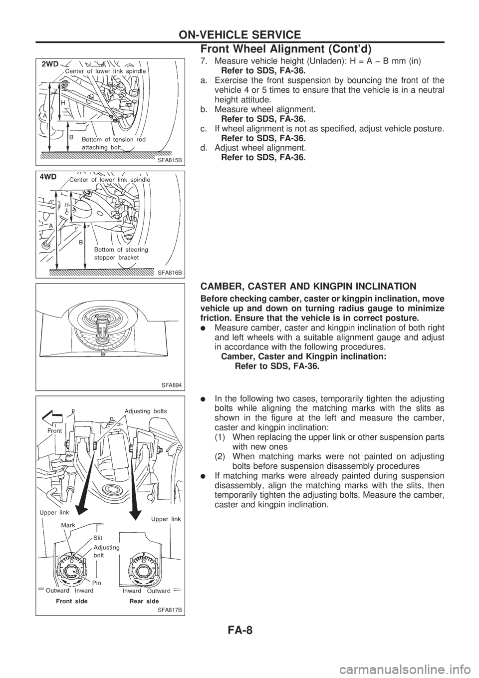
7. Measure vehicle height (Unladen):H=AþBmm(in)
Refer to SDS, FA-36.
a. Exercise the front suspension by bouncing the front of the
vehicle 4 or 5 times to ensure that the vehicle is in a neutral
height attitude.
b. Measure wheel alignment.
Refer to SDS, FA-36.
c. If wheel alignment is not as specified, adjust vehicle posture.
Refer to SDS, FA-36.
d. Adjust wheel alignment.
Refer to SDS, FA-36.
CAMBER, CASTER AND KINGPIN INCLINATION
Before checking camber, caster or kingpin inclination, move
vehicle up and down on turning radius gauge to minimize
friction. Ensure that the vehicle is in correct posture.
lMeasure camber, caster and kingpin inclination of both right
and left wheels with a suitable alignment gauge and adjust
in accordance with the following procedures.
Camber, Caster and Kingpin inclination:
Refer to SDS, FA-36.
lIn the following two cases, temporarily tighten the adjusting
bolts while aligning the matching marks with the slits as
shown in the figure at the left and measure the camber,
caster and kingpin inclination:
(1) When replacing the upper link or other suspension parts
with new ones
(2) When matching marks were not painted on adjusting
bolts before suspension disassembly procedures
lIf matching marks were already painted during suspension
disassembly, align the matching marks with the slits, then
temporarily tighten the adjusting bolts. Measure the camber,
caster and kingpin inclination.
SFA815B
SFA816B
SFA894
SFA817B
ON-VEHICLE SERVICE
Front Wheel Alignment (Cont'd)
FA-8
Page 775 of 1659

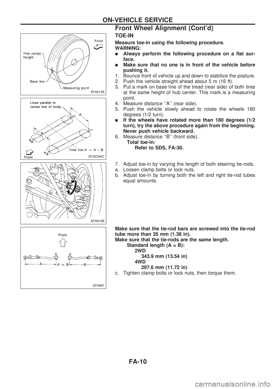
TOE-IN
Measure toe-in using the following procedure.
WARNING:
lAlways perform the following procedure on a flat sur-
face.
lMake sure that no one is in front of the vehicle before
pushing it.
1. Bounce front of vehicle up and down to stabilize the posture.
2. Push the vehicle straight ahead about 5 m (16 ft).
3. Put a mark on base line of the tread (rear side) of both tires
at the same height of hub center. This mark is a measuring
point.
4. Measure distance ``A'' (rear side).
5. Push the vehicle slowly ahead to rotate the wheels 180
degrees (1/2 turn).
lIf the wheels have rotated more than 180 degrees (1/2
turn), try the above procedure again from the beginning.
Never push vehicle backward.
6. Measure distance ``B'' (front side).
Total toe-in:
Refer to SDS, FA-36.
7. Adjust toe-in by varying the length of both steering tie-rods.
a. Loosen clamp bolts or lock nuts.
b. Adjust toe-in by turning both the left and right tie-rod tubes
equal amounts.
Make sure that the tie-rod bars are screwed into the tie-rod
tube more than 35 mm (1.38 in).
Make sure that the tie-rods are the same length.
Standard length (A = B):
2WD
343.9 mm (13.54 in)
4WD
297.6 mm (11.72 in)
c. Tighten clamp bolts or lock nuts, then torque them.
SFA614B
SFA234AC
SFA819B
SFA897
ON-VEHICLE SERVICE
Front Wheel Alignment (Cont'd)
FA-10