Page 15 of 1659
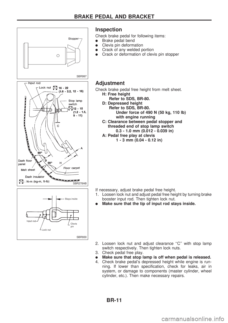
Inspection
Check brake pedal for following items:
lBrake pedal bend
lClevis pin deformation
lCrack of any welded portion
lCrack or deformation of clevis pin stopper
Adjustment
Check brake pedal free height from melt sheet.
H: Free height
Refer to SDS, BR-80.
D: Depressed height
Refer to SDS, BR-80.
Under force of 490 N (50 kg, 110 lb)
with engine running
C: Clearance between pedal stopper and
threaded end of stop lamp switch
0.3 - 1.0 mm (0.012 - 0.039 in)
A: Pedal free play at clevis
1-3mm(0.04 - 0.12 in)
If necessary, adjust brake pedal free height.
1. Loosen lock nut and adjust pedal free height by turning brake
booster input rod. Then tighten lock nut.
lMake sure that the tip of input rod stays inside.
2. Loosen lock nut and adjust clearance ``C'' with stop lamp
switch respectively. Then tighten lock nuts.
3. Check pedal free play.
lMake sure that stop lamp is off when pedal is released.
4. Check brake pedal's depressed height while engine is run-
ning. If lower than specification, check for leaks, air in
system, or damage to components (master cylinder, wheel
cylinder, etc.). Then make necessary repairs.
SBR997
SBR278AB
SBR930
BRAKE PEDAL AND BRACKET
BR-11
Page 84 of 1659

Inspection and Adjustment
DISC BRAKEUnit: mm (in)
Brake model CL28VD
Pad wear limit
Minimum thickness 2.0 (0.079)
Rotor repair limit
Minimum thickness 24.0 (0.945)
DRUM BRAKEUnit: mm (in)
Brake model LT26B LT30A
Lining wear limit
Minimum thickness 1.5 (0.059)
Drum repair limit
Maximum inner
diameter261.5 (10.30) 296.5 (11.67)
Out-of-round limit 0.15 (0.0059)
BRAKE PEDALUnit: mm (in)
Free height ``H''*
LHD 209 - 219 (8.23 - 8.62)
RHD 203 - 213 (7.99 - 8.39)
Depressed height ``D''
[under force of 490 N (50
kg, 110 lb) with engine run-
ning]120.0 (4.72)
Clearance ``C'' between
pedal stopper and threaded
end of stop lamp switch0.3 - 1.0 (0.012 - 0.039)
Pedal free play
At clevis 1.0 - 3.0 (0.039 - 0.118)
At pedal pad 4 - 12 (0.16 - 0.47)
*: Measured from surface of melt sheet to pedal pad.
PARKING BRAKE CONTROL
Control type Stick lever Center lever
Lever stroke
[under force of 196 N
(20 kg, 44 lb)]2WD 8 - 10 Ð
4WD 10-12 8-10
Lever stroke when warning
switch comes on1
SERVICE DATA AND SPECIFICATIONS (SDS)
BR-80
Page 90 of 1659
Adjusting Clutch Pedal
1. Adjust pedal height with pedal stopper.
2. Adjust pedal free play with push rod.
Air Bleeding Procedure
Bleed air according to the following procedure.
Bleed the air from the master cylinder (RHD models only)
and then the operating cylinder.
1. Fill the master cylinder reservoir tank with new brake fluid.
2. Connect a transparent vinyl hose to the air bleeder.
3. Slowly depress the clutch pedal to its full stroke length and
release it completely. Repeat this operation several times at
2 to 3 second intervals.
4. Open the air bleeder with the clutch pedal fully depressed.
5. Close the air bleeder.
6. Release the clutch pedal and wait at least 5 seconds.
7. Repeat steps 3 through 6 above until air bubbles no longer
appear in the brake fluid.
SCL742-A
.LHD model
221 - 231 mm (8.70 - 0.09 in)
RHD model
195 - 205 mm (7.68 - 8.07 in)
Pedal free play ``A'':
1 - 1.5 mm (0.039 - 0.059 in)
SCL203
INSPECTION AND ADJUSTMENT
CL-5
Page 99 of 1659
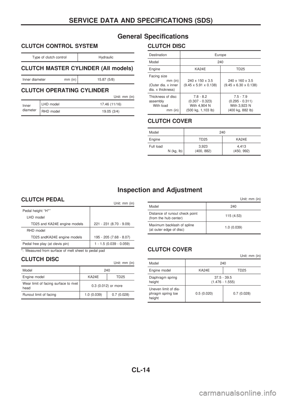
General Specifications
CLUTCH CONTROL SYSTEM
Type of clutch control Hydraulic
CLUTCH MASTER CYLINDER (All models)
Inner diameter mm (in) 15.87 (5/8)
CLUTCH OPERATING CYLINDER
Unit: mm (in)
Inner
diameterLHD model 17.46 (11/16)
RHD model 19.05 (3/4)
CLUTCH DISC
Destination Europe
Model 240
Engine KA24E TD25
Facing size
mm (in)
(Outer dia. x inner
dia. x thickness)240 x 150 x 3.5
(9.45 x 5.91 x 0.138)240 x 160 x 3.5
(9.45 x 6.30 x 0.138)
Thickness of disc
assembly
With load
mm (in)7.8 - 8.2
(0.307 - 0.323)
With 4,904 N
(500 kg, 1,103 lb)7.5 - 7.9
(0.295 - 0.311)
With 3,923 N
(400 kg, 882 lb)
CLUTCH COVER
Model 240
Engine TD25 KA24E
Full load
N (kg, lb)3,923
(400, 882)4,413
(450, 992)
Inspection and Adjustment
CLUTCH PEDALUnit: mm (in)
Pedal height ``H*''
LHD model
TD25 and KA24E engine models 221 - 231 (8.70 - 9.09)
RHD model
TD25 andKA24E engine models 195 - 205 (7.68 - 8.07)
Pedal free play (at clevis pin) 1 - 1.5 (0.039 - 0.059)
*: Measured from surface of melt sheet to pedal pad
CLUTCH DISCUnit: mm (in)
Model 240
Engine model KA24E TD25
Wear limit of facing surface to rivet
head0.3 (0.012) or more
Runout limit of facing 1.0 (0.039) 0.7 (0.028)
Unit: mm (in)
Model 240
Distance of runout check point
(from the hub center)115 (4.53)
Maximum backlash of spline
(at outer edge of disc)1.0 (0.039)
CLUTCH COVER
Unit: mm (in)
Model 240
Engine model KA24E TD25
Diaphragm spring
height37.5 - 39.5
(1.476 - 1.555)
Uneven limit of dia-
phragm spring toe
height0.5 (0.020) 0.7 (0.028)
SERVICE DATA AND SPECIFICATIONS (SDS)
CL-14
Page 736 of 1659
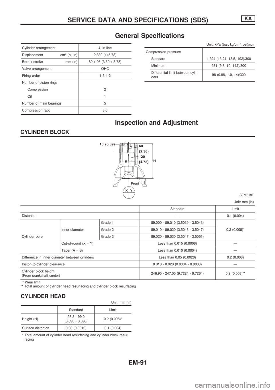
General Specifications
Cylinder arrangement 4, in-line
Displacement cm
3(cu in) 2,389 (145.78)
Bore x stroke mm (in) 89 x 96 (3.50 x 3.78)
Valve arrangement OHC
Firing order 1-3-4-2
Number of piston rings
Compression 2
Oil 1
Number of main bearings 5
Compression ratio 8.6
Unit: kPa (bar, kg/cm2, psi)/rpm
Compression pressure
Standard 1,324 (13.24, 13.5, 192)/300
Minimum 981 (9.8, 10, 142)/300
Differential limit between cylin-
ders98 (0.98, 1.0, 14)/300
Inspection and Adjustment
CYLINDER BLOCK
SEM618F
Unit: mm (in)
Standard Limit
DistortionÐ 0.1 (0.004)
Cylinder boreInner diameterGrade 1 89.000 - 89.010 (3.5039 - 3.5043)
0.2 (0.008)* Grade 2 89.010 - 89.020 (3.5043 - 3.5047)
Grade 3 89.020 - 89.030 (3.5047 - 3.5051)
Out-of-round (X þ Y) Less than 0.015 (0.0006) Ð
Taper (A þ B) Less than 0.010 (0.0004) Ð
Difference in inner diameter between cylinders Less than 0.05 (0.0020) 0.2 (0.008)
Piston-to-cylinder clearance 0.010 - 0.020 (0.0004 - 0.0008) Ð
Cylinder block height
(From crankshaft center)246.95 - 247.05 (9.7224 - 9.7264) 0.2 (0.008)**
* Wear limit
** Total amount of cylinder head resurfacing and cylinder block resurfacing
CYLINDER HEAD
Unit: mm (in)
Standard Limit
Height (H)98.8 - 99.0
(3.890 - 3.898)0.2 (0.008)*
Surface distortion 0.03 (0.0012) 0.1 (0.004)
* Total amount of cylinder head resurfacing and cylinder block resur-
facing
SERVICE DATA AND SPECIFICATIONS (SDS)KA
EM-91
Page 738 of 1659
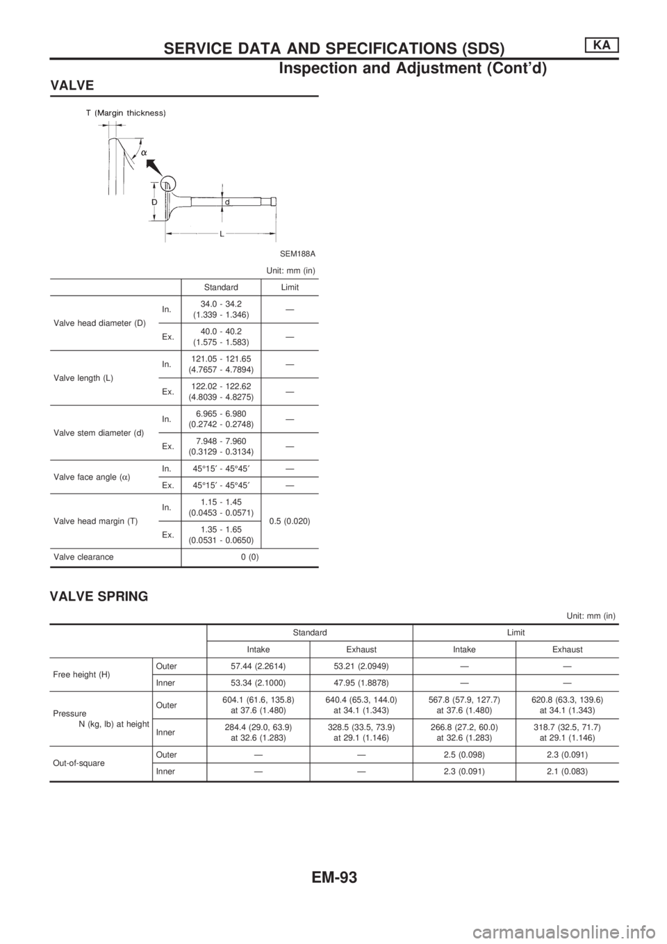
VALVE
SEM188A
Unit: mm (in)
Standard Limit
Valve head diameter (D)In.34.0 - 34.2
(1.339 - 1.346)Ð
Ex.40.0 - 40.2
(1.575 - 1.583)Ð
Valve length (L)In.121.05 - 121.65
(4.7657 - 4.7894)Ð
Ex.122.02 - 122.62
(4.8039 - 4.8275)Ð
Valve stem diameter (d)In.6.965 - 6.980
(0.2742 - 0.2748)Ð
Ex.7.948 - 7.960
(0.3129 - 0.3134)Ð
Valve face angle (a)In. 45É15¢- 45É45¢Ð
Ex. 45É15¢- 45É45¢Ð
Valve head margin (T)In.1.15 - 1.45
(0.0453 - 0.0571)
0.5 (0.020)
Ex.1.35 - 1.65
(0.0531 - 0.0650)
Valve clearance 0 (0)
VALVE SPRING
Unit: mm (in)
Standard Limit
Intake Exhaust Intake Exhaust
Free height (H)Outer 57.44 (2.2614) 53.21 (2.0949) Ð Ð
Inner 53.34 (2.1000) 47.95 (1.8878) Ð Ð
Pressure
N (kg, lb) at heightOuter604.1 (61.6, 135.8)
at 37.6 (1.480)640.4 (65.3, 144.0)
at 34.1 (1.343)567.8 (57.9, 127.7)
at 37.6 (1.480)620.8 (63.3, 139.6)
at 34.1 (1.343)
Inner284.4 (29.0, 63.9)
at 32.6 (1.283)328.5 (33.5, 73.9)
at 29.1 (1.146)266.8 (27.2, 60.0)
at 32.6 (1.283)318.7 (32.5, 71.7)
at 29.1 (1.146)
Out-of-squareOuter Ð Ð 2.5 (0.098) 2.3 (0.091)
Inner Ð Ð 2.3 (0.091) 2.1 (0.083)
SERVICE DATA AND SPECIFICATIONS (SDS)KA
Inspection and Adjustment (Cont'd)
EM-93
Page 739 of 1659
CAMSHAFT AND CAMSHAFT BEARING
SEM568A
EM120
Unit: mm (in)
Standard Limit
Cam height (A) 44.43 - 44.58 (1.7492 - 1.7551) Ð
Valve lift (h) 9.7 (0.382) Ð
Wear limit of cam height Ð 0.2 (0.008)
Camshaft journal to bearing clearance 0.045 - 0.090 (0.0018 - 0.0035) 0.12 (0.0047)
Inner diameter of camshaft bearing 33.000 - 33.025 (1.2992 - 1.3002) Ð
Outer diameter of camshaft journal (D) 32.935 - 32.955 (1.2967 - 1.2974) Ð
Camshaft runout 0 - 0.02 (0 - 0.0008) Ð
Camshaft end play 0.07 - 0.15 (0.0028 - 0.0059) 0.2 (0.008)
Valve timing (Degree on crankshaft)a 232 Ð
b 232 Ð
cþ5 Ð
d57 Ð
e11 Ð
f41 Ð
ROCKER ARM AND ROCKER SHAFT
Unit: mm (in)
Rocker arm to shaft clearance 0.012 - 0.050 (0.0005 - 0.0020)
Rocker shaft diameter21.979 - 22.000
(0.8653 - 0.8661)
Rocker arm rocker shaft hole
diameter22.012 - 22.029
(0.8666 - 0.8673)
SERVICE DATA AND SPECIFICATIONS (SDS)KA
Inspection and Adjustment (Cont'd)
EM-94
Page 743 of 1659
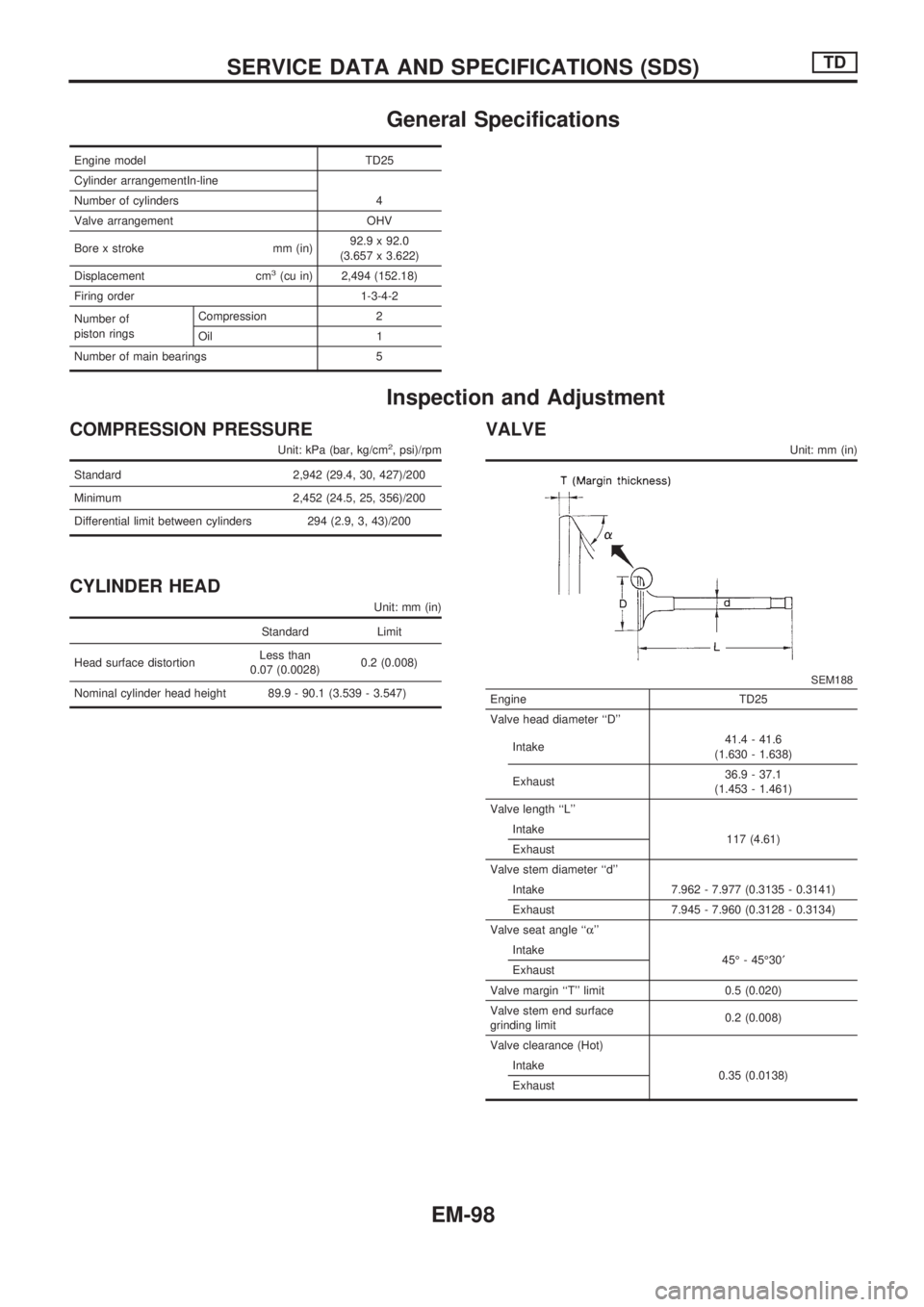
General Specifications
Engine model TD25
Cylinder arrangementIn-line
Number of cylinders 4
Valve arrangement OHV
Bore x stroke mm (in)92.9 x 92.0
(3.657 x 3.622)
Displacement cm
3(cu in) 2,494 (152.18)
Firing order 1-3-4-2
Number of
piston ringsCompression 2
Oil 1
Number of main bearings 5
Inspection and Adjustment
COMPRESSION PRESSURE
Unit: kPa (bar, kg/cm2, psi)/rpm
Standard 2,942 (29.4, 30, 427)/200
Minimum 2,452 (24.5, 25, 356)/200
Differential limit between cylinders 294 (2.9, 3, 43)/200
CYLINDER HEAD
Unit: mm (in)
Standard Limit
Head surface distortionLess than
0.07 (0.0028)0.2 (0.008)
Nominal cylinder head height 89.9 - 90.1 (3.539 - 3.547)
VALVE
Unit: mm (in)
SEM188
Engine TD25
Valve head diameter ``D''
Intake41.4 - 41.6
(1.630 - 1.638)
Exhaust36.9 - 37.1
(1.453 - 1.461)
Valve length ``L''
Intake
117 (4.61)
Exhaust
Valve stem diameter ``d''
Intake 7.962 - 7.977 (0.3135 - 0.3141)
Exhaust 7.945 - 7.960 (0.3128 - 0.3134)
Valve seat angle ``a''
Intake
45É - 45É30¢
Exhaust
Valve margin ``T'' limit 0.5 (0.020)
Valve stem end surface
grinding limit0.2 (0.008)
Valve clearance (Hot)
Intake
0.35 (0.0138)
Exhaust
SERVICE DATA AND SPECIFICATIONS (SDS)TD
EM-98