1998 NISSAN PICK-UP oil
[x] Cancel search: oilPage 5 of 1659

Supplemental Restraint System (SRS) ``AIR
BAG'' (4WD models)
The Supplemental Restraint System ``AIR BAG'', used along with a seat belt, helps to reduce the risk or
severity of injury to the driver in a frontal collision. The Supplemental Restraint System consists of air bag
module (located in the center of the steering wheel), a diagnosis sensor unit, warning lamp, wiring harness
and spiral cable. Information necessary to service the system safely is included in theRS sectionof this
Service Manual.
WARNING:
lTo avoid rendering the SRS inoperative, which could increase the risk of personal injury or death
in the event of a collision which would result in air bag inflation, all maintenance must be per-
formed by an authorized NISSAN dealer.
lImproper maintenance, including incorrect removal and installation of the SRS, can lead to per-
sonal injury caused by unintentional activation of the system.
lDo not use electrical test equipment on any circuit related to the SRS unless instructed to in this
Service Manual. SRS wiring harnesses are covered with yellow insulation either just before the
harness connectors or for the complete harness, for easy identification.
Supplemental Restraint System (SRS) ``AIR
BAG'' (2WD models)
The Supplemental Restraint System ``AIR BAG'', used along with a seat belt, helps to reduce the risk or
severity of injury to the driver in a frontal collision. The Supplemental Restraint System consists of an air
bag module (located in the center of the steering wheel), a diagnosis sensor unit, warning lamp and spiral
cable. Information necessary to service the system safely is included in theRS sectionof this Service
Manual.
WARNING:
lTo avoid rendering the SRS inoperative, which could increase the risk of personal injury or death
in the event of a collision which would result in air bag inflation, all maintenance must be per-
formed by an authorized NISSAN dealer.
lImproper maintenance, including incorrect removal and installation of the SRS, can lead to per-
sonal injury caused by unintentional activation of the system.
lDo not use electrical test equipment on any circuit related to the SRS.
Precautions for Brake System
lUse brake fluid DOT 3 or DOT 4*1.
lNever reuse drained brake fluid.
lBe careful not to splash brake fluid on painted areas; it
may cause paint damage. If brake fluid is splashed on
painted areas, wash it away with water immediately.
lTo clean master cylinder parts, disc brake caliper parts
or wheel cylinder parts, use clean brake fluid.
lNever use mineral oils such as gasoline or kerosene.
They will ruin rubber parts of the hydraulic system.
lUse flare nut wrench when removing and installing brake
tubes.
lAlways torque brake lines when installing.
WARNING:
lClean brakes with a vacuum dust collector to minimize
the hazard of airborne materials.
*1: Refer to MA section (``Fluids and Lubricants'', ``RECOM-
MENDED FLUIDS AND LUBRICANTS'').
SBR820BA
PRECAUTIONS AND PREPARATION
BR-1
Page 7 of 1659

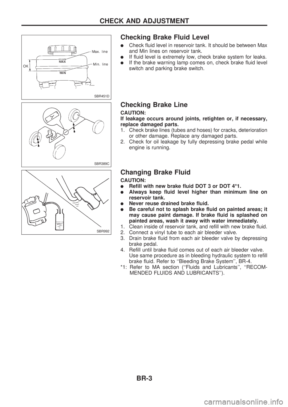
Checking Brake Fluid Level
lCheck fluid level in reservoir tank. It should be between Max
and Min lines on reservoir tank.
lIf fluid level is extremely low, check brake system for leaks.
lIf the brake warning lamp comes on, check brake fluid level
switch and parking brake switch.
Checking Brake Line
CAUTION:
If leakage occurs around joints, retighten or, if necessary,
replace damaged parts.
1. Check brake lines (tubes and hoses) for cracks, deterioration
or other damage. Replace any damaged parts.
2. Check for oil leakage by fully depressing brake pedal while
engine is running.
Changing Brake Fluid
CAUTION:
lRefill with new brake fluid DOT 3 or DOT 4*1.
lAlways keep fluid level higher than minimum line on
reservoir tank.
lNever reuse drained brake fluid.
lBe careful not to splash brake fluid on painted areas; it
may cause paint damage. If brake fluid is splashed on
painted areas, wash it away with water immediately.
1. Clean inside of reservoir tank, and refill with new brake fluid.
2. Connect a vinyl tube to each air bleeder valve.
3. Drain brake fluid from each air bleeder valve by depressing
brake pedal.
4. Refill until brake fluid comes out of each air bleeder valve.
Use same procedure as in bleeding hydraulic system to refill
brake fluid. Refer to ``Bleeding Brake System'', BR-4.
*1: Refer to MA section (``Fluids and Lubricants'', ``RECOM-
MENDED FLUIDS AND LUBRICANTS'').
SBR451D
SBR389C
SBR992
CHECK AND ADJUSTMENT
BR-3
Page 13 of 1659

INSPECTION
1. Ensure vehicle is unladen condition*.
* Fuel, radiator coolant and engine oil full. Spare tire, jack,
hand tools and mats in designated positions.
2. Have a driver sit in the driver's seat and one person sit on
the rear of the vehicle. Then have the person on the rear of
the vehicle slowly get off. This is necessary to stabilize sus-
pension deflection.
3. Adjust length ``L'' as follows:
a. Loosen stopper bolt locknut (2WD JIDOSHA KIKI make).
b. Pull lever against stopper bolt and adjust by turning stopper
bolt.
c. Tighten stopper bolt locknut (2WD JIDOSHA KIKI make).
Length ``L'':
2WD models
Approx. 187.3 mm (7.37 in)
4WD models
Approx. 158.1 mm (6.22 in)
4. Install pressure gauge to front and rear brake air bleeder.
5. Bleed air from the Tool.
6. Raise front brake pressure to 4,904 kPa (49.0 bar, 50
kg/cm
2, 711 psi) and 9,807 kPa (98.1 bar, 100 kg/cm2, 1,422
psi) and check rear brake pressure.
Rear brake pressure:
Refer to table below.
7. Set down weight slowly over axle center so that sensor
spring length becomes the same as when in loaded condi-
tion (refer to table below). Check rear brake pressure in the
same way described in step 6.
Unit: kPa (bar, kg/cm2, psi)
Front brake
pressureRear brake pressure
2WD 4WD
Unladen
condition
L = 187.3 mm
(7.37 in)Loaded
condition
L = 204.0 mm
(8.03 in)Unladen
condition
L = 158.1 mm
(6.22 in)Loaded
condition
L = 184.0 mm
(7.24 in)
4,904
(49.0, 50, 711)1,667 - 2,648
(16.7 - 26.5, 17
- 27, 242 - 384)3,334 - 4,315
(33.3 - 43.2, 34
- 44, 483 - 626)1,863 - 2,844
(18.6 - 28.4, 19
- 29, 270 - 412)3,334 - 4,315
(33.3 - 43.2, 34
- 44, 483 - 626)
9,807
(98.1, 100,
1,422)2,844 - 3,825
(28.4 - 38.2, 29
- 39, 412 - 555)3,629 - 5,590
(36.3 - 55.9, 37
- 57, 526 - 811)2,059 - 4,021
(20.6 - 40.2, 21
- 41, 299 - 583)3,629 - 5,590
(36.3 - 55.9, 37
- 57, 526 - 811)
SBR967D
SBR968D
SBR013B
SBR014B
CONTROL VALVE
Load Sensing Valve (Cont'd)
BR-9
Page 21 of 1659

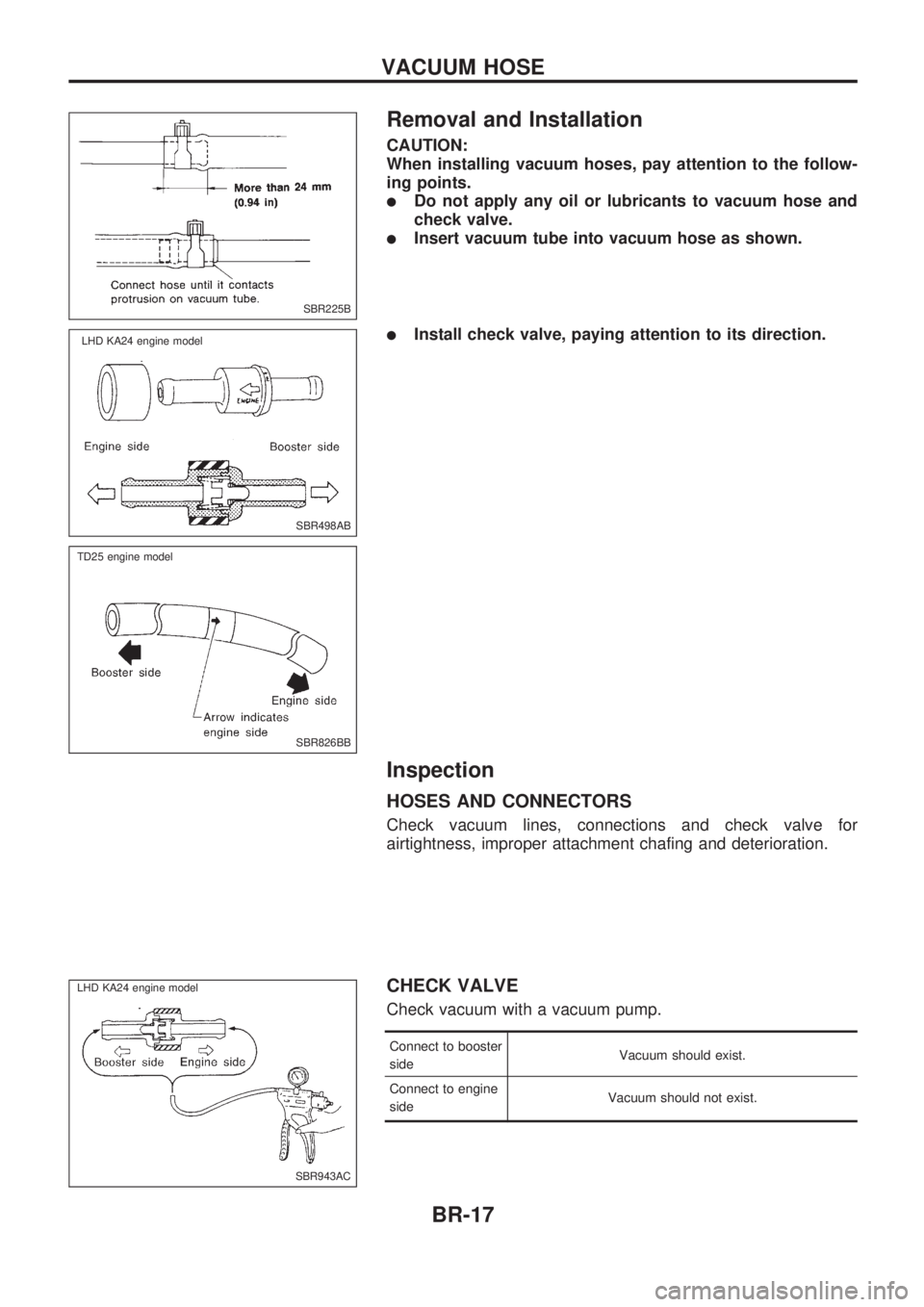
Removal and Installation
CAUTION:
When installing vacuum hoses, pay attention to the follow-
ing points.
lDo not apply any oil or lubricants to vacuum hose and
check valve.
lInsert vacuum tube into vacuum hose as shown.
lInstall check valve, paying attention to its direction.
Inspection
HOSES AND CONNECTORS
Check vacuum lines, connections and check valve for
airtightness, improper attachment chafing and deterioration.
CHECK VALVE
Check vacuum with a vacuum pump.
Connect to booster
sideVacuum should exist.
Connect to engine
sideVacuum should not exist.
SBR225B
SBR498AB
.LHD KA24 engine model
SBR826BB
.TD25 engine model
SBR943AC
.LHD KA24 engine model.
VACUUM HOSE
BR-17
Page 25 of 1659

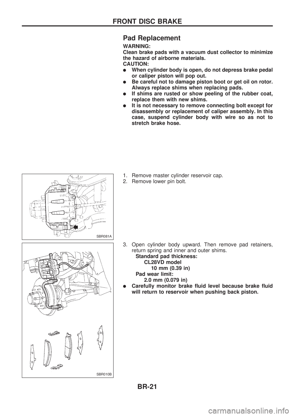
Pad Replacement
WARNING:
Clean brake pads with a vacuum dust collector to minimize
the hazard of airborne materials.
CAUTION:
lWhen cylinder body is open, do not depress brake pedal
or caliper piston will pop out.
lBe careful not to damage piston boot or get oil on rotor.
Always replace shims when replacing pads.
lIf shims are rusted or show peeling of the rubber coat,
replace them with new shims.
lIt is not necessary to remove connecting bolt except for
disassembly or replacement of caliper assembly. In this
case, suspend cylinder body with wire so as not to
stretch brake hose.
1. Remove master cylinder reservoir cap.
2. Remove lower pin bolt.
3. Open cylinder body upward. Then remove pad retainers,
return spring and inner and outer shims.
Standard pad thickness:
CL28VD model
10 mm (0.39 in)
Pad wear limit:
2.0 mm (0.079 in)
lCarefully monitor brake fluid level because brake fluid
will return to reservoir when pushing back piston.
SBR081A
SBR010B
FRONT DISC BRAKE
BR-21
Page 27 of 1659

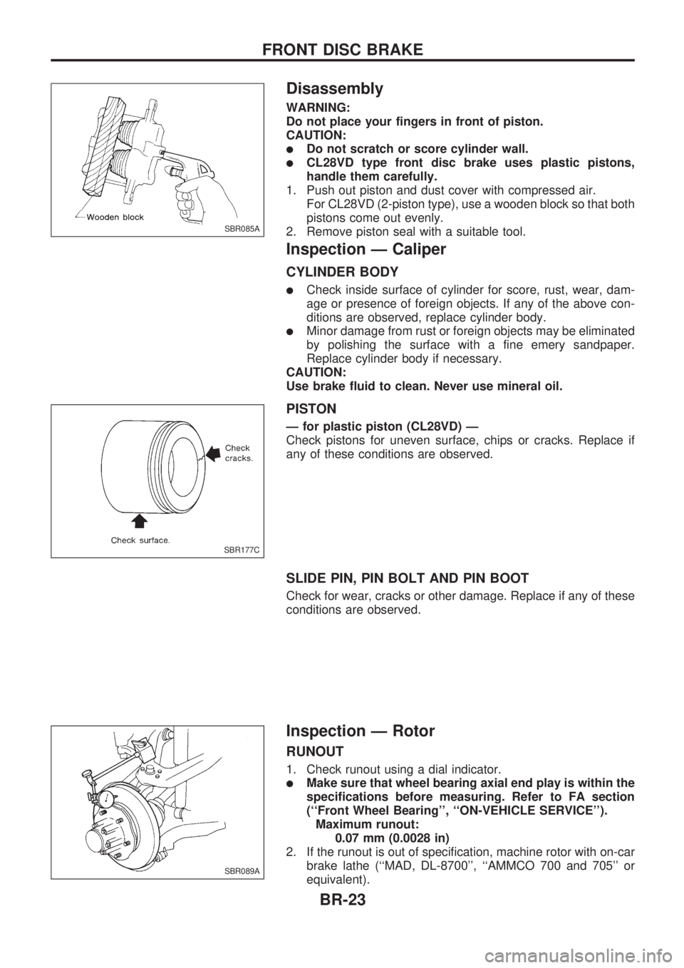
Disassembly
WARNING:
Do not place your fingers in front of piston.
CAUTION:
lDo not scratch or score cylinder wall.
lCL28VD type front disc brake uses plastic pistons,
handle them carefully.
1. Push out piston and dust cover with compressed air.
For CL28VD (2-piston type), use a wooden block so that both
pistons come out evenly.
2. Remove piston seal with a suitable tool.
Inspection Ð Caliper
CYLINDER BODY
lCheck inside surface of cylinder for score, rust, wear, dam-
age or presence of foreign objects. If any of the above con-
ditions are observed, replace cylinder body.
lMinor damage from rust or foreign objects may be eliminated
by polishing the surface with a fine emery sandpaper.
Replace cylinder body if necessary.
CAUTION:
Use brake fluid to clean. Never use mineral oil.
PISTON
Ð for plastic piston (CL28VD) Ð
Check pistons for uneven surface, chips or cracks. Replace if
any of these conditions are observed.
SLIDE PIN, PIN BOLT AND PIN BOOT
Check for wear, cracks or other damage. Replace if any of these
conditions are observed.
Inspection Ð Rotor
RUNOUT
1. Check runout using a dial indicator.
lMake sure that wheel bearing axial end play is within the
specifications before measuring. Refer to FA section
(``Front Wheel Bearing'', ``ON-VEHICLE SERVICE'').
Maximum runout:
0.07 mm (0.0028 in)
2. If the runout is out of specification, machine rotor with on-car
brake lathe (``MAD, DL-8700'', ``AMMCO 700 and 705'' or
equivalent).
SBR085A
SBR177C
SBR089A
FRONT DISC BRAKE
BR-23
Page 37 of 1659

System Components
System Description
WHEEL SENSOR
The sensor unit consists of a gear-shaped sensor rotor and a
sensor element. The element contains a bar magnet around
which a coil is wound. The sensor is installed on the back of the
brake rotor and the front of the differential (2WD) or the back of
the rear brake drum (4WD). As the wheel rotates, the sensor
generates a sine-wave pattern. The frequency and voltage
increase(s) as the rotating speed increases.
CONTROL UNIT (built in ABS actuator and electric
unit)
The control unit computes the wheel rotating speed by the sig-
nal current sent from the sensor. Then it supplies a DC current
to the actuator solenoid valve. It also controls ON-OFF operation
of the valve relay and motor relay. If any electrical malfunction
should be detected in the system, the control unit causes the
warning lamp to light up. In this condition, the ABS will be deac-
tivated by the control unit, and the vehicle's brake system reverts
to normal operation. (For control unit layout, refer to ABS
ACTUATOR AND ELECTRIC UNIT, BR-34.)
SBR068E
SBR069E
ANTI-LOCK BRAKE SYSTEM
BR-33
Page 59 of 1659

MALFUNCTION CODE/SYMPTOM CHART
Code No.
(No. of warning lamp flashes)Malfunctioning part Diagnostic procedure
45 Actuator front left outlet solenoid valve 2
46 Actuator front left inlet solenoid valve 2
41 Actuator front right outlet solenoid valve 2
42 Actuator front right inlet solenoid valve 2
55 Actuator rear outlet solenoid valve 2
56 Actuator rear inlet solenoid valve 2
25.3 Front left sensor (open-circuit) 1
26.3 Front left sensor (short-circuit) 1
21.3 Front right sensor (open-circuit) 1
22.3 Front right sensor (short-circuit) 1
35.1,.3 Rear sensor (open-circuit) 1
36.1,.3 Rear sensor (short-circuit) 1
31.2,.3 Rear right sensor (open-circuit) 1
32.2,.3 Rear right sensor (short-circuit) 1
35.2,.3 Rear left sensor (open-circuit) 1
36.2,.3 Rear left sensor (short-circuit) 1
18.3 Sensor rotor 1
17.2 G sensor and circuit 5
61.5 Actuator motor or motor relay 3
63 Solenoid valve relay 2
57.4 Power supply (Low voltage) 4
71 Control unit 6
Warning lamp stays on when igni-
tion switch is turned onControl unit power supply circuit
Warning lamp bulb circuit
Control unit or control unit connector
Solenoid valve relay stuck
Power supply for solenoid valve relay coil13
Warning lamp does not come on
when ignition switch is turned onFuse, warning lamp bulb or warning lamp circuit
Control unit12
Pedal vibration and noise Ð 11
Long stopping distance Ð 9
Unexpected pedal action Ð 8
ABS does not work Ð 10
ABS works frequently Ð 7
.1: 2WD model only
.2: 4WD model only
.3: If one or more wheels spin on a rough or slippery road for 40 seconds or more, the ABS warning lamp will illuminate. This does
not indicate a malfunction. Only in the case of the short-circuit (Code Nos. 26, 22, 32 and 36), after repair the ABS warning
lamp also illuminates when the ignition switch is turned ``ON''. In this case, drive the vehicle at speeds greater than 30 km/h (19
MPH) for approximately 1 minute as specified in ``SELF-DIAGNOSIS PROCEDURE'', BR-53. Check to ensure that the ABS
warning lamp goes out while the vehicle is being driven.
.4: The trouble code ``57'', which refers to a low power supply voltage, does not indicate that the ABS control unit is malfunctioning.
Do not replace the ABS control unit with a new one.
.5: The trouble code ``61'' can sometimes appear when the ABS motor is not properly grounded. If it appears, be sure to check the
condition of the ABS motor ground circuit connection.
TROUBLE DIAGNOSES
Self-diagnosis (Cont'd)
BR-55