1998 NISSAN PICK-UP fuse box
[x] Cancel search: fuse boxPage 815 of 1659

Description
Number Item Description
V1Power conditionlThis shows the condition when the system receives battery positive voltage (can
be operated).
V2Fusible link
lThe double line shows that this is a fusible link.
lThe open circle shows current flow in, and the shaded circle shows current flow
out.
V3Fusible link/fuse locationlThis shows the location of the fusible link or fuse in the fusible link or fuse box.
For arrangement, refer to EL section (``POWER SUPPLY ROUTING'').
V4Fuse
lThe single line shows that this is a fuse.
lThe open circle shows current flow in, and the shaded circle shows current flow
out.
V5Current ratinglThis shows the current rating of the fusible link or fuse.
V6Connectors
lThis shows that connectorE3is female and connectorM1is male.
lThe G/R wire is located in the 1A terminal of both connectors.
lTerminal number with an alphabet (1A, 5B, etc.) indicates that the connector is
SMJ connector. Refer to GI-17.
V7Optional splicelThe open circle shows that the splice is optional depending on vehicle application.
V8SplicelThe shaded circle shows that the splice is always on the vehicle.
V9Page crossinglThis arrow shows that the circuit continues to an adjacent page.
lThe A will match with the A on the preceding or next page.
V10Common connectorlThe dotted lines between terminals show that these terminals are part of the same
connector.
V11Option abbreviationlThis shows that the circuit is optional depending on vehicle application.
V12RelaylThis shows an internal representation of the relay. For details, refer to EL section
(``STANDARDIZED RELAY'').
V13ConnectorslThis shows that the connector is connected to the body or a terminal with bolt or
nut.
V14Wire color
lThis shows a code for the color of the wire.
B = Black BR = Brown
W = White OR = Orange
R = Red P = Pink
G = Green PU = Purple
L = Blue GY = Gray
Y = Yellow SB = Sky Blue
LG = Light Green CH = Dark Brown
DG = Dark Green
When the wire color is striped, the base color is given first, followed by the stripe
color as shown below:
Example: L/W = Blue with White Stripe
V15Option descriptionlThis shows a description of the option abbreviation used on the page.
V16Switch
lThis shows that continuity exists between terminals 1 and 2 when the switch is in
the A position. Continuity exists between terminals 1 and 3 when the switch is in
the B position.
V17Assembly partslConnector terminal in component shows that it is a harness incorporated assem-
bly.
V18Cell codelThis identifies each page of the wiring diagram by section, system and wiring dia-
gram page number.
HOW TO READ WIRING DIAGRAMS
GI-11
Page 816 of 1659

Number Item Description
V19Current flow arrow
lArrow indicates electric current flow, especially where the direction of standard
flow (vertically downward or horizontally from left to right) is difficult to follow.
lA double arrow ``bÐ
c'' shows that current can flow in either direction depending
on circuit operation.
V20System branchlThis shows that the system branches to another system identified by cell code
(section and system).
V21Page crossing
lThis arrow shows that the circuit continues to another page identified by cell code.
lThe C will match with the C on another page within the system other than the next
or preceding pages.
V22Shielded linelThe line enclosed by broken line circle shows shield wire.
V23Component box in wave
linelThis shows that another part of the component is also shown on another page
(indicated by wave line) within the system.
V24Component namelThis shows the name of a component.
V25Connector number
lThis shows the connector number.
lThe letter shows which harness the connector is located in.
Example:M: main harness. For detail and to locate the connector, refer to EL sec-
tion (``Main Harness'', ``HARNESS LAYOUT''). A coordinate grid is included for
complex harnesses to aid in locating connectors.
V26Ground (GND)lThe line spliced and grounded under wire color shows that ground line is spliced
at the grounded connector.
V27Ground (GND)lThis shows the ground connection.
V28Connector viewslThis area shows the connector faces of the components in the wiring diagram on
the page.
V29Common componentlConnectors enclosed in broken line show that these connectors belong to the
same component.
V30Connector colorlThis shows a code for the color of the connector. For code meaning, refer to wire
color codes, Number
V14of this chart.
V31Fusible link and fuse box
lThis shows the arrangement of fusible link(s) and fuse(s), used for connector
views of ``POWER SUPPLY ROUTING'' in EL section.
The open square shows current flow in, and the shaded square shows current
flow out.
V32Reference arealThis shows that more information on the Super Multiple Junction (SMJ) and Joint
Connectors (J/C) exists on the foldout page. Refer to GI-17 for details.
HOW TO READ WIRING DIAGRAMS
Description (Cont'd)
GI-12
Page 976 of 1659
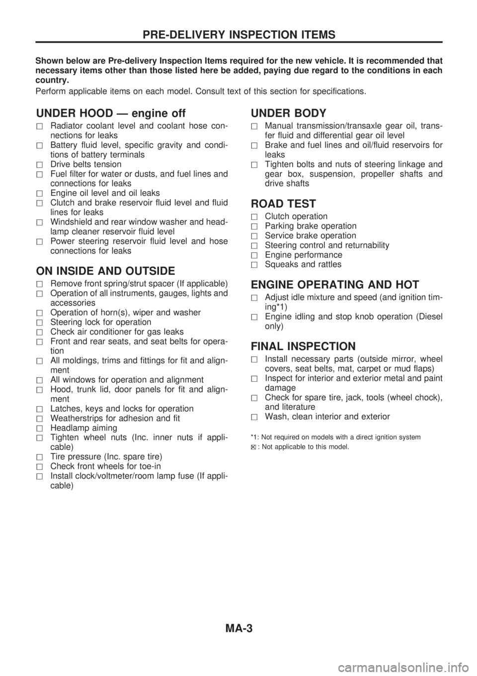
Shown below are Pre-delivery Inspection Items required for the new vehicle. It is recommended that
necessary items other than those listed here be added, paying due regard to the conditions in each
country.
Perform applicable items on each model. Consult text of this section for specifications.
UNDER HOOD Ð engine off
hRadiator coolant level and coolant hose con-
nections for leaks
hBattery fluid level, specific gravity and condi-
tions of battery terminals
hDrive belts tension
hFuel filter for water or dusts, and fuel lines and
connections for leaks
hEngine oil level and oil leaks
hClutch and brake reservoir fluid level and fluid
lines for leaks
hWindshield and rear window washer and head-
lamp cleaner reservoir fluid level
hPower steering reservoir fluid level and hose
connections for leaks
ON INSIDE AND OUTSIDE
hRemove front spring/strut spacer (If applicable)
hOperation of all instruments, gauges, lights and
accessories
hOperation of horn(s), wiper and washer
hSteering lock for operation
hCheck air conditioner for gas leaks
hFront and rear seats, and seat belts for opera-
tion
hAll moldings, trims and fittings for fit and align-
ment
hAll windows for operation and alignment
hHood, trunk lid, door panels for fit and align-
ment
hLatches, keys and locks for operation
hWeatherstrips for adhesion and fit
hHeadlamp aiming
hTighten wheel nuts (Inc. inner nuts if appli-
cable)
hTire pressure (Inc. spare tire)
hCheck front wheels for toe-in
hInstall clock/voltmeter/room lamp fuse (If appli-
cable)
UNDER BODY
hManual transmission/transaxle gear oil, trans-
fer fluid and differential gear oil level
hBrake and fuel lines and oil/fluid reservoirs for
leaks
hTighten bolts and nuts of steering linkage and
gear box, suspension, propeller shafts and
drive shafts
ROAD TEST
hClutch operation
hParking brake operation
hService brake operation
hSteering control and returnability
hEngine performance
hSqueaks and rattles
ENGINE OPERATING AND HOT
hAdjust idle mixture and speed (and ignition tim-
ing*1)
hEngine idling and stop knob operation (Diesel
only)
FINAL INSPECTION
hInstall necessary parts (outside mirror, wheel
covers, seat belts, mat, carpet or mud flaps)
hInspect for interior and exterior metal and paint
damage
hCheck for spare tire, jack, tools (wheel chock),
and literature
hWash, clean interior and exterior
*1: Not required on models with a direct ignition system
h
X: Not applicable to this model.
PRE-DELIVERY INSPECTION ITEMS
MA-3
Page 1346 of 1659
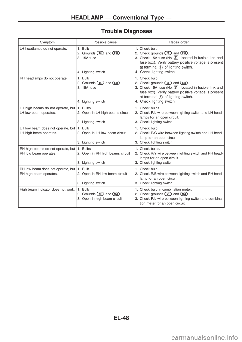
Trouble Diagnoses
Symptom Possible cause Repair order
LH headlamps do not operate. 1. Bulb
2. Grounds
E6andE39
3. 15A fuse
4. Lighting switch1. Check bulb.
2. Check grounds
E6andE39.
3. Check 15A fuse (No.
32, located in fusible link and
fuse box). Verify battery positive voltage is present
at terminal
V8of lighting switch.
4. Check lighting switch.
RH headlamps do not operate. 1. Bulb
2. Grounds
E6andE39
3. 15A fuse
4. Lighting switch1. Check bulb.
2. Check grounds
E6andE39.
3. Check 15A fuse (No.
31, located in fusible link and
fuse box). Verify battery positive voltage is present
at terminal
V5of lighting switch.
4. Check lighting switch.
LH high beams do not operate, but
LH low beam operates.1. Bulbs
2. Open in LH high beams circuit
3. Lighting switch1. Check bulbs.
2. Check R/L wire between lighting switch and LH head-
lamps for an open circuit.
3. Check lighting switch.
LH low beam does not operate, but
LH high beam operates.1. Bulb
2. Open in LH low beam circuit
3. Lighting switch1. Check bulb.
2. Check R/G wire between lighting switch and LH head-
lamp for an open circuit.
3. Check lighting switch.
RH high beams do not operate, but
RH low beam operates.1. Bulbs
2. Open in RH high beams circuit
3. Lighting switch1. Check bulbs.
2. Check R/Y wire between lighting switch and RH head-
lamps for an open circuit.
3. Check lighting switch.
RH low beam does not operate, but
RH high beam operates.1. Bulb
2. Open in RH low beam circuit
3. Lighting switch1. Check bulb.
2. Check R/B wire between lighting switch and RH head-
lamp for an open circuit.
3. Check lighting switch.
High beam indicator does not work. 1. Bulb
2. Grounds
M1andM54
3. Open in high beam circuit1. Check bulb in combination meter.
2. Check grounds
M1andM54.
3. Check R/L wire between lighting switch and combina-
tion meter for an open circuit.
HEADLAMP Ð Conventional Type Ð
EL-48
Page 1452 of 1659
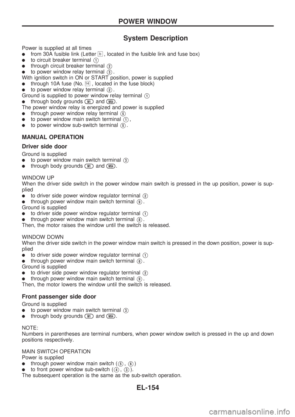
System Description
Power is supplied at all times
lfrom 30A fusible link (Letterb, located in the fusible link and fuse box)
lto circuit breaker terminalV1
lthrough circuit breaker terminalV2
lto power window relay terminalV3.
With ignition switch in ON or START position, power is supplied
lthrough 10A fuse (No.14, located in the fuse block)
lto power window relay terminalV2.
Ground is supplied to power window relay terminal
V1
lthrough body groundsM1andM54.
The power window relay is energized and power is supplied
lthrough power window relay terminalV5
lto power window main switch terminalV1,
lto power window sub-switch terminalV5.
MANUAL OPERATION
Driver side door
Ground is supplied
lto power window main switch terminalV3
lthrough body groundsM1andM54.
WINDOW UP
When the driver side switch in the power window main switch is pressed in the up position, power is sup-
plied
lto driver side power window regulator terminalV2
lthrough power window main switch terminalV9.
Ground is supplied
lto driver side power window regulator terminalV1
lthrough power window main switch terminalV8.
Then, the motor raises the window until the switch is released.
WINDOW DOWN
When the driver side switch in the power window main switch is pressed in the down position, power is sup-
plied
lto driver side power window regulator terminalV1
lthrough power window main switch terminalV8.
Ground is supplied
lto driver side power window regulator terminalV2
lthrough power window main switch terminalV9.
Then, the motor lowers the window until the switch is released.
Front passenger side door
Ground is supplied
lto power window main switch terminalV3
lthrough body groundsM1andM54.
NOTE:
Numbers in parentheses are terminal numbers, when power window switch is pressed in the up and down
positions respectively.
MAIN SWITCH OPERATION
Power is supplied
lthrough power window main switch (V5,V6)
lto front power window sub-switch (V4,V3).
The subsequent operation is the same as the sub-switch operation.
POWER WINDOW
EL-154
Page 1463 of 1659
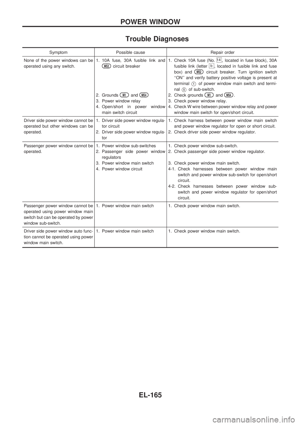
Trouble Diagnoses
Symptom Possible cause Repair order
None of the power windows can be
operated using any switch.1. 10A fuse, 30A fusible link and
M52circuit breaker
2. Grounds
M1andM54
3. Power window relay
4. Open/short in power window
main switch circuit1. Check 10A fuse (No.
14, located in fuse block), 30A
fusible link (letter
b, located in fusible link and fuse
box) and
M52circuit breaker. Turn ignition switch
``ON'' and verify battery positive voltage is present at
terminal
V1of power window main switch and termi-
nal
V5of sub-switch.
2. Check grounds
M1andM54.
3. Check power window relay.
4. Check W wire between power window relay and power
window main switch for open/short circuit.
Driver side power window cannot be
operated but other windows can be
operated.1. Driver side power window regula-
tor circuit
2. Driver side power window regula-
tor1. Check harness between power window main switch
and power window regulator for open or short circuit.
2. Check driver side power window regulator.
Passenger power window cannot be
operated.1. Power window sub-switches
2. Passenger side power window
regulators
3. Power window main switch
4. Power window circuit1. Check power window sub-switch.
2. Check passenger side power window regulator.
3. Check power window main switch.
4-1. Check harnesses between power window main
switch and power window sub-switch for open/short
circuit.
4-2. Check harnesses between power window sub-
switch and power window regulator for open/short
circuit.
Passenger power window cannot be
operated using power window main
switch but can be operated by power
window sub-switch.1. Power window main switch 1. Check power window main switch.
Driver side power window auto func-
tion cannot be operated using power
window main switch.1. Power window main switch 1. Check power window main switch.
POWER WINDOW
EL-165
Page 1464 of 1659
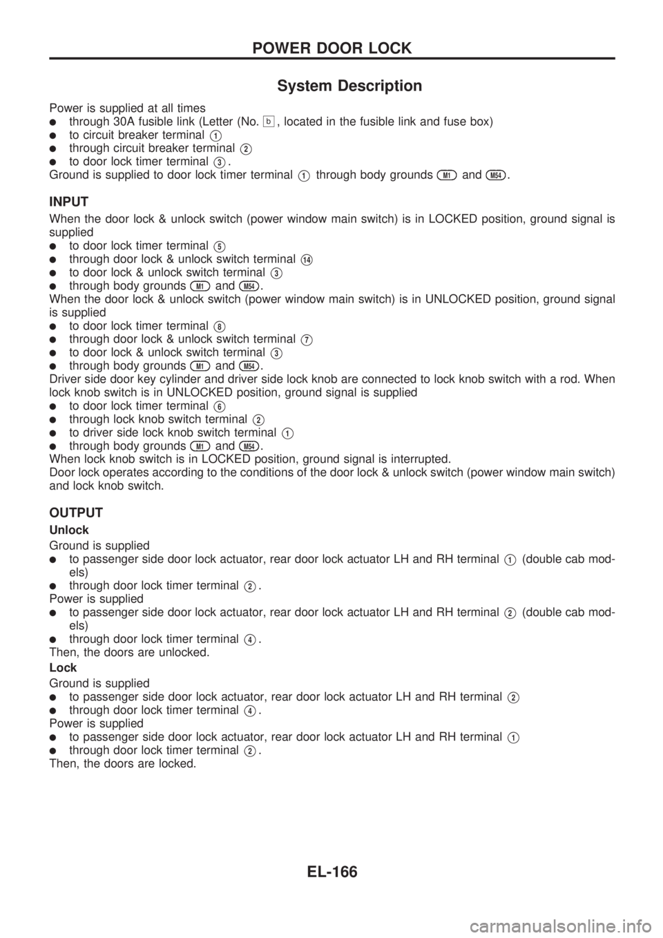
System Description
Power is supplied at all times
lthrough 30A fusible link (Letter (No.b, located in the fusible link and fuse box)
lto circuit breaker terminalV1
lthrough circuit breaker terminalV2
lto door lock timer terminalV3.
Ground is supplied to door lock timer terminal
V1through body groundsM1andM54.
INPUT
When the door lock & unlock switch (power window main switch) is in LOCKED position, ground signal is
supplied
lto door lock timer terminalV5
lthrough door lock & unlock switch terminalV14
lto door lock & unlock switch terminalV3
lthrough body groundsM1andM54.
When the door lock & unlock switch (power window main switch) is in UNLOCKED position, ground signal
is supplied
lto door lock timer terminalV8
lthrough door lock & unlock switch terminalV7
lto door lock & unlock switch terminalV3
lthrough body groundsM1andM54.
Driver side door key cylinder and driver side lock knob are connected to lock knob switch with a rod. When
lock knob switch is in UNLOCKED position, ground signal is supplied
lto door lock timer terminalV6
lthrough lock knob switch terminalV2
lto driver side lock knob switch terminalV1
lthrough body groundsM1andM54.
When lock knob switch is in LOCKED position, ground signal is interrupted.
Door lock operates according to the conditions of the door lock & unlock switch (power window main switch)
and lock knob switch.
OUTPUT
Unlock
Ground is supplied
lto passenger side door lock actuator, rear door lock actuator LH and RH terminalV1(double cab mod-
els)
lthrough door lock timer terminalV2.
Power is supplied
lto passenger side door lock actuator, rear door lock actuator LH and RH terminalV2(double cab mod-
els)
lthrough door lock timer terminalV4.
Then, the doors are unlocked.
Lock
Ground is supplied
lto passenger side door lock actuator, rear door lock actuator LH and RH terminalV2
lthrough door lock timer terminalV4.
Power is supplied
lto passenger side door lock actuator, rear door lock actuator LH and RH terminalV1
lthrough door lock timer terminalV2.
Then, the doors are locked.
POWER DOOR LOCK
EL-166
Page 1479 of 1659
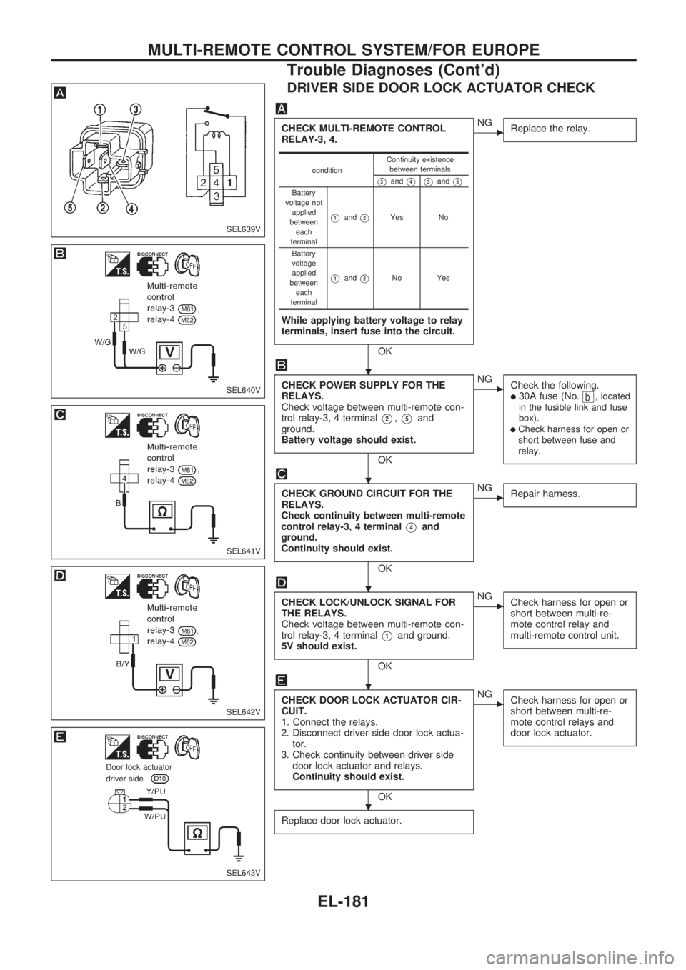
DRIVER SIDE DOOR LOCK ACTUATOR CHECK
CHECK MULTI-REMOTE CONTROL
RELAY-3, 4.
While applying battery voltage to relay
terminals, insert fuse into the circuit.
OK
cNG
Replace the relay.
CHECK POWER SUPPLY FOR THE
RELAYS.
Check voltage between multi-remote con-
trol relay-3, 4 terminal
V2,V5and
ground.
Battery voltage should exist.
OK
cNG
Check the following.
l30A fuse (No.b, located
in the fusible link and fuse
box).
lCheck harness for open or
short between fuse and
relay.
CHECK GROUND CIRCUIT FOR THE
RELAYS.
Check continuity between multi-remote
control relay-3, 4 terminal
V4and
ground.
Continuity should exist.
OK
cNG
Repair harness.
CHECK LOCK/UNLOCK SIGNAL FOR
THE RELAYS.
Check voltage between multi-remote con-
trol relay-3, 4 terminal
V1and ground.
5V should exist.
OK
cNG
Check harness for open or
short between multi-re-
mote control relay and
multi-remote control unit.
CHECK DOOR LOCK ACTUATOR CIR-
CUIT.
1. Connect the relays.
2. Disconnect driver side door lock actua-
tor.
3. Check continuity between driver side
door lock actuator and relays.
Continuity should exist.
OK
cNG
Check harness for open or
short between multi-re-
mote control relays and
door lock actuator.
Replace door lock actuator.
conditionContinuity existence
between terminals
V3andV4V3andV5
Battery
voltage not
applied
between
each
terminal
V1andV2Yes No
Battery
voltage
applied
between
each
terminal
V1andV2No Yes
SEL639V
SEL640V
SEL641V
SEL642V
SEL643V
.Door lock actuator.driver side
.
.
.
.
.
MULTI-REMOTE CONTROL SYSTEM/FOR EUROPE
Trouble Diagnoses (Cont'd)
EL-181