1998 NISSAN PICK-UP width
[x] Cancel search: widthPage 82 of 1659
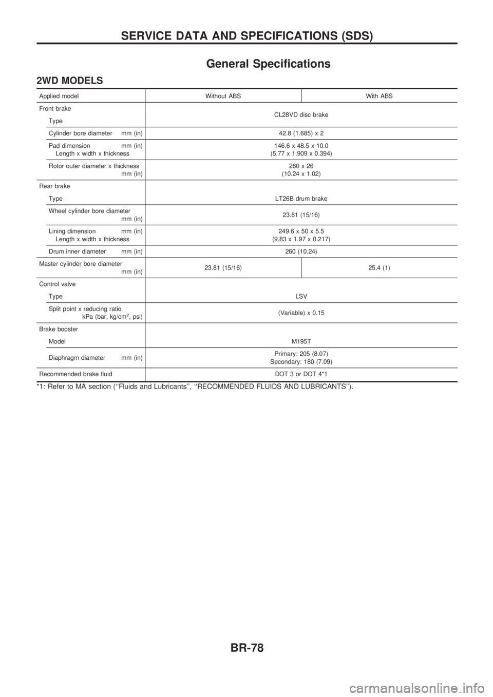
General Specifications
2WD MODELS
Applied model Without ABS With ABS
Front brake
CL28VD disc brake
Type
Cylinder bore diameter mm (in) 42.8 (1.685) x 2
Pad dimension mm (in)
Length x width x thickness146.6 x 48.5 x 10.0
(5.77 x 1.909 x 0.394)
Rotor outer diameter x thickness
mm (in)260x26
(10.24 x 1.02)
Rear brake
TypeLT26B drum brake
Wheel cylinder bore diameter
mm (in)23.81 (15/16)
Lining dimension mm (in)
Length x width x thickness249.6 x 50 x 5.5
(9.83 x 1.97 x 0.217)
Drum inner diameter mm (in) 260 (10.24)
Master cylinder bore diameter
mm (in)23.81 (15/16) 25.4 (1)
Control valve
TypeLSV
Split point x reducing ratio
kPa (bar, kg/cm
2, psi)(Variable) x 0.15
Brake booster
ModelM195T
Diaphragm diameter mm (in)Primary: 205 (8.07)
Secondary: 180 (7.09)
Recommended brake fluid DOT 3 or DOT 4*1
*1: Refer to MA section (``Fluids and Lubricants'', ``RECOMMENDED FLUIDS AND LUBRICANTS'').
SERVICE DATA AND SPECIFICATIONS (SDS)
BR-78
Page 83 of 1659
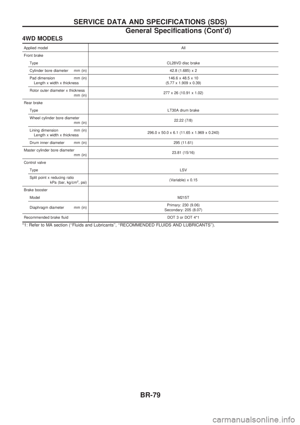
4WD MODELS
Applied modelAll
Front brake
TypeCL28VD disc brake
Cylinder bore diameter mm (in) 42.8 (1.685) x 2
Pad dimension mm (in)
Length x width x thickness146.6 x 48.5 x 10
(5.77 x 1.909 x 0.39)
Rotor outer diameter x thickness
mm (in)277 x 26 (10.91 x 1.02)
Rear brake
TypeLT30A drum brake
Wheel cylinder bore diameter
mm (in)22.22 (7/8)
Lining dimension mm (in)
Length x width x thickness296.0 x 50.0 x 6.1 (11.65 x 1.969 x 0.240)
Drum inner diameter mm (in) 295 (11.61)
Master cylinder bore diameter
mm (in)23.81 (15/16)
Control valve
TypeLSV
Split point x reducing ratio
kPa (bar, kg/cm
2, psi)(Variable) x 0.15
Brake booster
ModelM215T
Diaphragm diameter mm (in)Primary: 230 (9.06)
Secondary: 205 (8.07)
Recommended brake fluid DOT 3 or DOT 4*1
*1: Refer to MA section (``Fluids and Lubricants'', ``RECOMMENDED FLUIDS AND LUBRICANTS'').
SERVICE DATA AND SPECIFICATIONS (SDS)
General Specifications (Cont'd)
BR-79
Page 167 of 1659

MIXTURE RATIO FEEDBACK CONTROL
The mixture ratio feedback system provides the best air-fuel
mixture ratio for driveability and emission control. The three way
catalyst can then better reduce CO, HC and NOx emissions. This
system uses a heated oxygen sensor in the exhaust manifold to
monitor if the engine is rich or lean. The ECM adjusts the injec-
tion pulse width according to the sensor voltage signal. For more
information about heated oxygen sensor, refer to page EC-123.
This maintains the mixture ratio within the range of stoichiomet-
ric (ideal air-fuel mixture).
This stage is referred to as the closed loop control condition.
OPEN LOOP CONTROL
The open loop system condition refers to when the ECM detects
any of the following conditions. Feedback control stops in order
to maintain stabilized fuel combustion.
lDeceleration and acceleration
lHigh-load, high-speed operation
lEngine idling
lMalfunction of heated oxygen sensor or its circuit
lInsufficient activation of heated oxygen sensor at low engine
coolant temperature
lHigh-engine coolant temperature
lDuring warm-up
lWhen starting the engine
MIXTURE RATIO SELF-LEARNING CONTROL
The mixture ratio feedback control system monitors the mixture
ratio signal transmitted from the heated oxygen sensor. This
feedback signal is then sent to the ECM. The ECM controls the
basic mixture ratio as close to the theoretical mixture ratio as
possible. However, the basic mixture ratio is not necessarily con-
trolled as originally designed. Both Manufacturing differences
(i.e. mass air flow sensor hot wire) and characteristic changes
during operation (i.e. injector clogging) directly affect mixture
ratio.
Accordingly, the difference between the basic and theoretical
mixture ratios is monitored in this system. This is then computed
in terms of ``injection pulse duration'' to automatically compen-
sate for the difference between the two ratios.
FUEL INJECTION SYSTEM
Two types of systems are used.
Sequential multiport fuel injection system
Fuel is injected into each cylinder during each engine cycle
according to the firing order. This system is used when the
engine is running.
MEF025DD
MEF522D
ENGINE AND EMISSION BASIC CONTROL SYSTEM DESCRIPTIONKA
Multiport Fuel Injection (MFI) System
(Cont'd)
EC-15
Page 168 of 1659
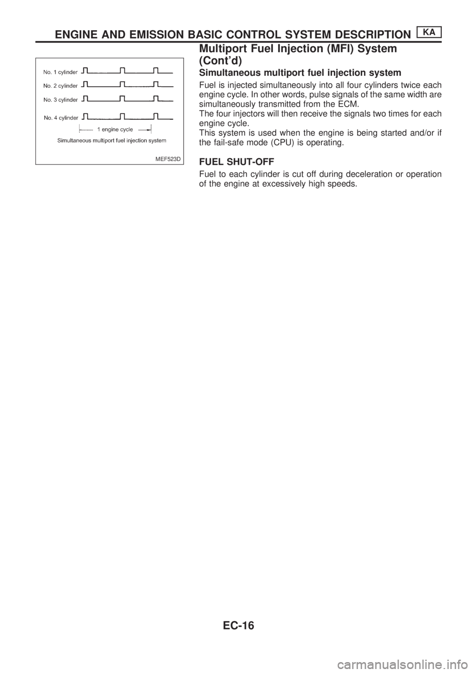
Simultaneous multiport fuel injection system
Fuel is injected simultaneously into all four cylinders twice each
engine cycle. In other words, pulse signals of the same width are
simultaneously transmitted from the ECM.
The four injectors will then receive the signals two times for each
engine cycle.
This system is used when the engine is being started and/or if
the fail-safe mode (CPU) is operating.
FUEL SHUT-OFF
Fuel to each cylinder is cut off during deceleration or operation
of the engine at excessively high speeds.
MEF523D
ENGINE AND EMISSION BASIC CONTROL SYSTEM DESCRIPTIONKA
Multiport Fuel Injection (MFI) System
(Cont'd)
EC-16
Page 169 of 1659

Distributor Ignition (DI) System
INPUT/OUTPUT SIGNAL LINE
Camshaft position sensorcEngine speed and piston position
ECM
(ECCS
control
module)
cPower
transistor
Mass air flow sensorcAmount of intake air
Engine coolant temperature sensor
cEngine coolant temperature
Throttle position sensor
c
Throttle position
Throttle valve idle position
Vehicle speed sensor
cVehicle speed
Ignition switch
cStart signal
Intake air temperature sensor
cIntake air temperature
Neutral position switch
cGear position
Battery
cBattery voltage
SYSTEM DESCRIPTION
The ignition timing is controlled by the ECM to maintain the best
air-fuel ratio for every running condition of the engine.
The ignition timing data is stored in the ECM. This data forms the
map shown left.
The ECM detects information such as the injection pulse width
and camshaft position sensor signal. Responding to this
information, ignition signals are transmitted to the power transis-
tor.
e.g. N: 1,800 rpm, Tp: 1.50 msec
A ÉBTDC
During the following conditions, the ignition timing is revised by
the ECM according to the other data stored in the ECM.
1 At starting
2 During warm-up
3 At idle
4 When swirl control valve operates
5 Hot-engine operation
6 At acceleration
SEF742M
ENGINE AND EMISSION BASIC CONTROL SYSTEM DESCRIPTIONKA
EC-17
Page 201 of 1659
![NISSAN PICK-UP 1998 Repair Manual Monitored item
[Unit]ECM
input
signalsMain
signalsDescription Remarks
INJ PULSE [msec]
j
lIndicates the actual fuel injection pulse
width compensated by ECM according to
the input signals.lWhen the en NISSAN PICK-UP 1998 Repair Manual Monitored item
[Unit]ECM
input
signalsMain
signalsDescription Remarks
INJ PULSE [msec]
j
lIndicates the actual fuel injection pulse
width compensated by ECM according to
the input signals.lWhen the en](/manual-img/5/57374/w960_57374-200.png)
Monitored item
[Unit]ECM
input
signalsMain
signalsDescription Remarks
INJ PULSE [msec]
j
lIndicates the actual fuel injection pulse
width compensated by ECM according to
the input signals.lWhen the engine is stopped, a certain
computed value is indicated.
IGN TIMING [BTDC]
j
lIndicates the ignition timing computed by
ECM according to the input signals.lWhen the engine is stopped, a certain
value is indicated.
IACV-AAC/V [%]
j
lIndicates the idle air control valve (AAC
valve) control value computed by ECM
according to the input signals.
A/F ALPHA [%]
j
lThe mean value of the air-fuel ratio feed-
back correction factor per cycle is indi-
cated.lWhen the engine is stopped, a certain
value is indicated.
lThis data also includes the data for the
air-fuel ratio learning control.
AIR COND RLY
[ON/OFF]
j
lThe air conditioner relay control condition
(determined by ECM according to the
input signal) is indicated.
FUEL PUMP RLY
[ON/OFF]
j
lIndicates the fuel pump relay control con-
dition determined by ECM according to
the input signals.
SWRL CONT S/V
[ON/OFF]
j
lThe control condition of the swirl control
valve control solenoid valve (determined
by the ECM according to the input signal)
is indicated.
ON ... Swirl control valve is closed
OFF ... Swirl control valve is open
EGRC SOL/V
(EVAP canister purge
control solenoid
valve) [ON/OFF]
j
lThe control condition of the EVAP canis-
ter purge control solenoid valve (deter-
mined by ECM according to the input
signal) is indicated.
ON ... EVAP canister purge control is not
operating
OFF ... EVAP canister purge control is
operational.
VOLTAGE
[V]
lVoltage measured by the voltage probe.
PULSE
[msec] or [Hz] or [%]
lPulse width, frequency or duty cycle
measured by the pulse probe.lOnly ``#'' is displayed if item is unable to
be measured.
lFigures with ``#''s are temporary ones.
They are the same figures as an actual
piece of data which was just previously
measured.
ON BOARD DIAGNOSTIC SYSTEM DESCRIPTIONKA
CONSULT (Cont'd)
EC-49
Page 676 of 1659
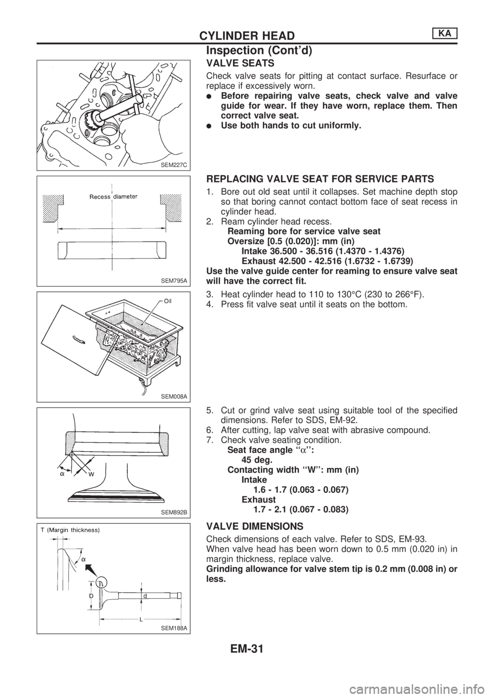
VALVE SEATS
Check valve seats for pitting at contact surface. Resurface or
replace if excessively worn.
lBefore repairing valve seats, check valve and valve
guide for wear. If they have worn, replace them. Then
correct valve seat.
lUse both hands to cut uniformly.
REPLACING VALVE SEAT FOR SERVICE PARTS
1. Bore out old seat until it collapses. Set machine depth stop
so that boring cannot contact bottom face of seat recess in
cylinder head.
2. Ream cylinder head recess.
Reaming bore for service valve seat
Oversize [0.5 (0.020)]: mm (in)
Intake 36.500 - 36.516 (1.4370 - 1.4376)
Exhaust 42.500 - 42.516 (1.6732 - 1.6739)
Use the valve guide center for reaming to ensure valve seat
will have the correct fit.
3. Heat cylinder head to 110 to 130ÉC (230 to 266ÉF).
4. Press fit valve seat until it seats on the bottom.
5. Cut or grind valve seat using suitable tool of the specified
dimensions. Refer to SDS, EM-92.
6. After cutting, lap valve seat with abrasive compound.
7. Check valve seating condition.
Seat face angle ``a'':
45 deg.
Contacting width ``W'': mm (in)
Intake
1.6 - 1.7 (0.063 - 0.067)
Exhaust
1.7 - 2.1 (0.067 - 0.083)
VALVE DIMENSIONS
Check dimensions of each valve. Refer to SDS, EM-93.
When valve head has been worn down to 0.5 mm (0.020 in) in
margin thickness, replace valve.
Grinding allowance for valve stem tip is 0.2 mm (0.008 in) or
less.
SEM227C
SEM795A
SEM008A
SEM892B
SEM188A
CYLINDER HEADKA
Inspection (Cont'd)
EM-31
Page 724 of 1659
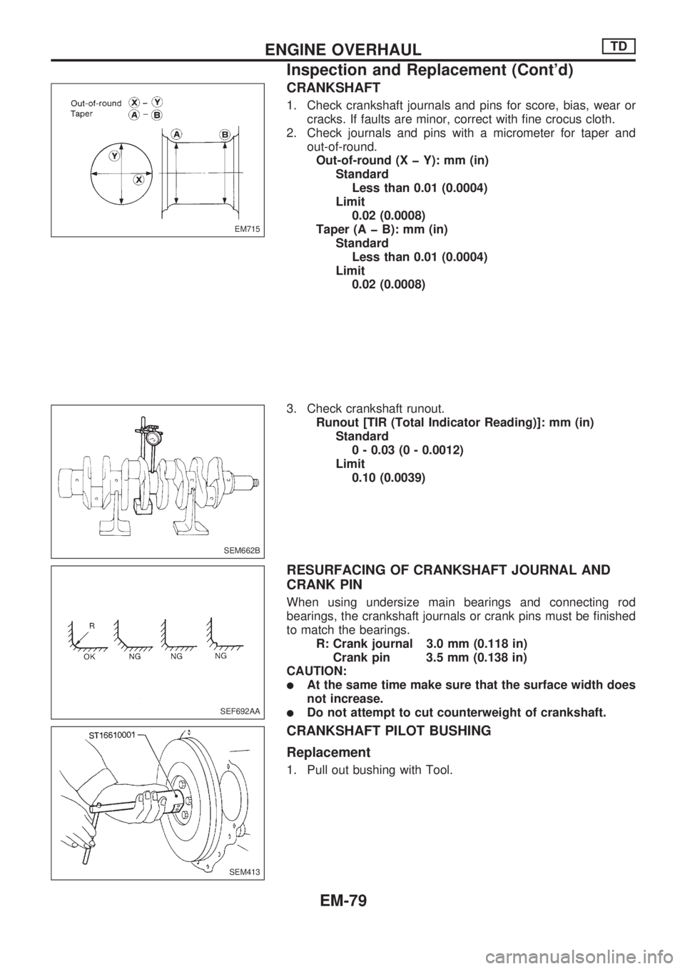
CRANKSHAFT
1. Check crankshaft journals and pins for score, bias, wear or
cracks. If faults are minor, correct with fine crocus cloth.
2. Check journals and pins with a micrometer for taper and
out-of-round.
Out-of-round (X þ Y): mm (in)
Standard
Less than 0.01 (0.0004)
Limit
0.02 (0.0008)
Taper (A þ B): mm (in)
Standard
Less than 0.01 (0.0004)
Limit
0.02 (0.0008)
3. Check crankshaft runout.
Runout [TIR (Total Indicator Reading)]: mm (in)
Standard
0 - 0.03 (0 - 0.0012)
Limit
0.10 (0.0039)
RESURFACING OF CRANKSHAFT JOURNAL AND
CRANK PIN
When using undersize main bearings and connecting rod
bearings, the crankshaft journals or crank pins must be finished
to match the bearings.
R: Crank journal 3.0 mm (0.118 in)
Crank pin 3.5 mm (0.138 in)
CAUTION:
lAt the same time make sure that the surface width does
not increase.
lDo not attempt to cut counterweight of crankshaft.
CRANKSHAFT PILOT BUSHING
Replacement
1. Pull out bushing with Tool.
EM715
SEM662B
SEF692AA
SEM413
ENGINE OVERHAULTD
Inspection and Replacement (Cont'd)
EM-79