1998 NISSAN PICK-UP tow
[x] Cancel search: towPage 856 of 1659
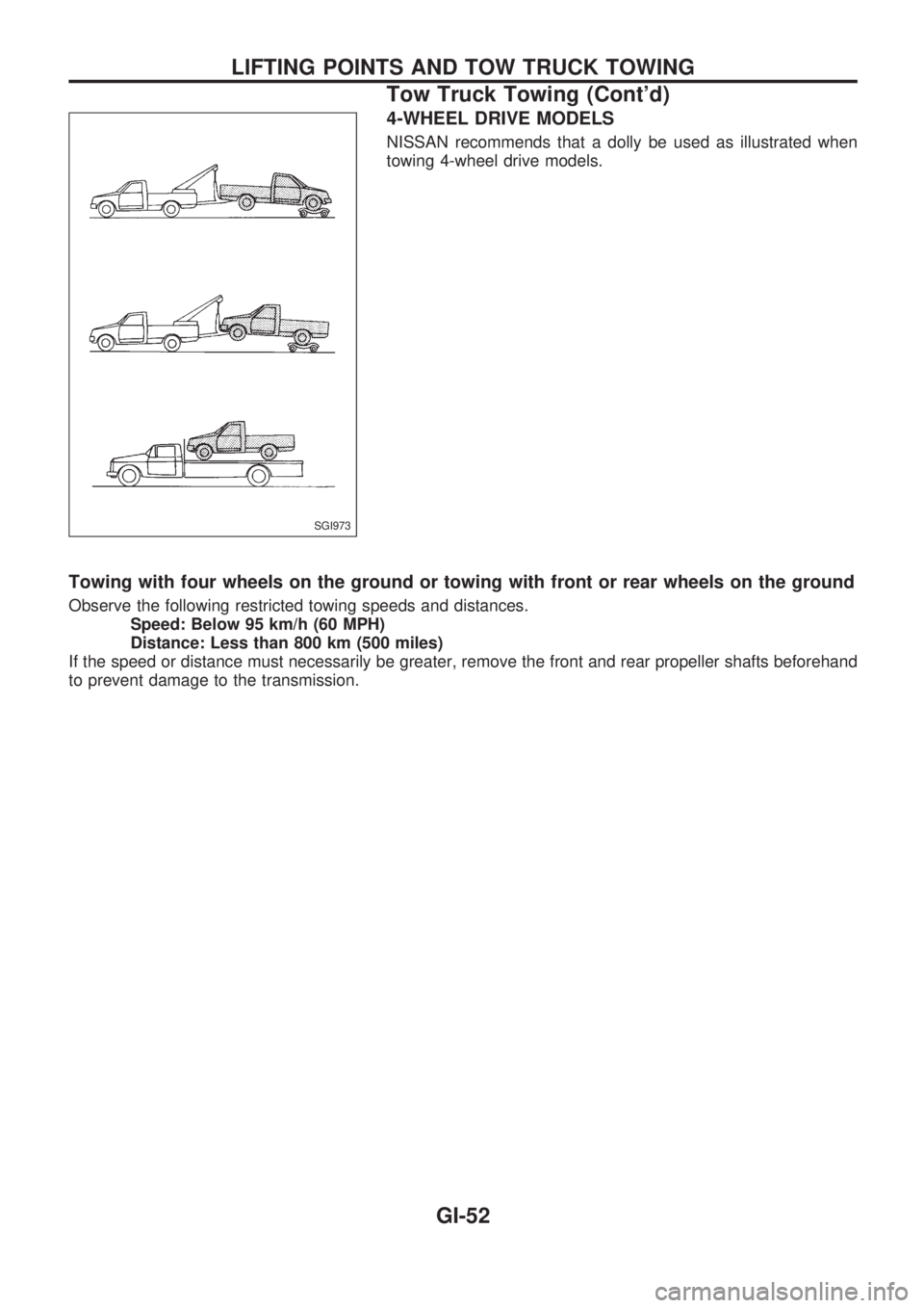
4-WHEEL DRIVE MODELS
NISSAN recommends that a dolly be used as illustrated when
towing 4-wheel drive models.
Towing with four wheels on the ground or towing with front or rear wheels on the ground
Observe the following restricted towing speeds and distances.
Speed: Below 95 km/h (60 MPH)
Distance: Less than 800 km (500 miles)
If the speed or distance must necessarily be greater, remove the front and rear propeller shafts beforehand
to prevent damage to the transmission.
SGI973
LIFTING POINTS AND TOW TRUCK TOWING
Tow Truck Towing (Cont'd)
GI-52
Page 857 of 1659
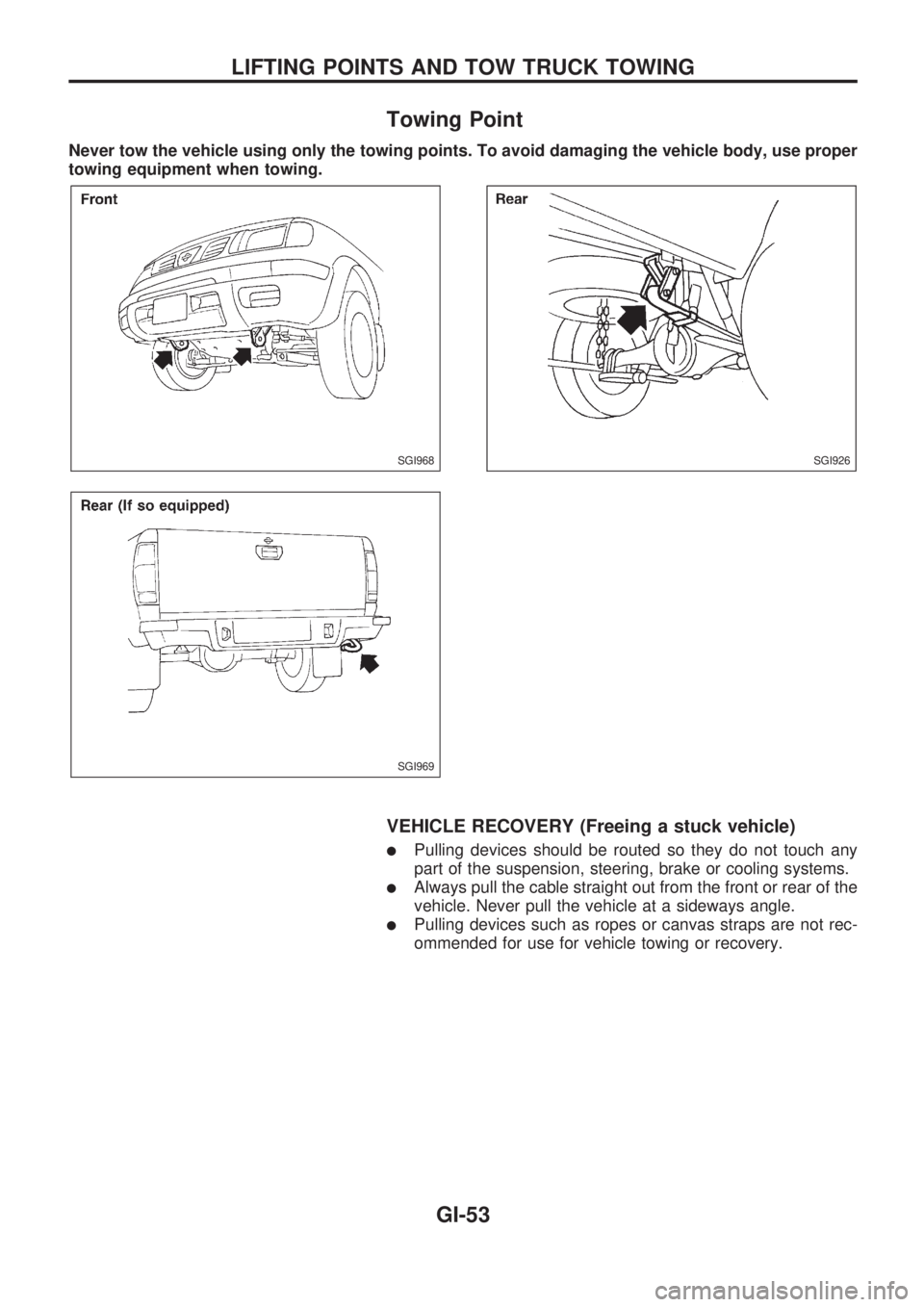
Towing Point
Never tow the vehicle using only the towing points. To avoid damaging the vehicle body, use proper
towing equipment when towing.
VEHICLE RECOVERY (Freeing a stuck vehicle)
lPulling devices should be routed so they do not touch any
part of the suspension, steering, brake or cooling systems.
lAlways pull the cable straight out from the front or rear of the
vehicle. Never pull the vehicle at a sideways angle.
lPulling devices such as ropes or canvas straps are not rec-
ommended for use for vehicle towing or recovery.
SGI968
SGI969
SGI926
LIFTING POINTS AND TOW TRUCK TOWING
GI-53
Page 870 of 1659
Throttle body ................................................. EM-9
Throttle position sensor (TPS)................... EC-113
Throwout bearing - See Clutch release
bearing........................................................ CL-9
Tie-rod .......................................................... ST-37
Tie-rod ball joints.......................................... ST-37
Tightening torque of standard bolts .............. GI-54
Timing chain ................................................ EM-13
Timing gear ................................................. EM-89
Tire rotation ................................................. MA-35
Tire size ........................................................ GI-46
Tooth contact (R180A) ................................ PD-26
Tooth contact (C200) ................................... PD-49
Tooth contact (H233B) ................................ PD-70
Torsion bar spring ........................................ FA-28
Tow truck towing ........................................... GI-51
Towing point.................................................. GI-53
Transfer case ................................................. TF-8
Transfer oil replacement ............................. MA-33
Transfer serial number.................................. GI-43
Transmission case (M/T) (FS5R30A).......... MT-35
Transmission case (M/T) (FS5W71C)......... MT-14
Transmission serial number.......................... GI-43
Tread - FR&RR (Dimensions) ...................... GI-44
Trim .............................................................. BT-15
Triple pressure switch ........................... HA-12, 44
Turn signal lamp........................................... EL-74
Two-pole lift................................................... GI-50
U
Under body ....................................................BT-46
Upper link (front susp.) ................................ FA-31
V
VSS - Wiring diagram .................................EC-119
Vacuum hose (brake system) .......................BR-17
Vacuum hose drawing (ECCS).....................EC-12
Vacuum pump ...............................................BR-19
Valve clearance adjustment .........................MA-23
Valve clearance ............................................EM-31
Valve guide (KA24 engine) ......................... EM-29Valve guide (TD25 engine) ..........................EM-56
Valve lifter .....................................................EM-60
Valve seat (KA24 engine) ............................EM-31
Valve seat (TD25 engine) ............................EM-57
Valve spring (KA24 engine) .........................EM-32
Valve spring (TD25 engine) .........................EM-60
Vehicle identification number .........................GI-40
Vehicle recovery (freeing a stuck
vehicle) .......................................................GI-53
Vehicle speed sensor (VSS).......................EC-118
Ventilator door control rod adjustment .........HA-45
Viscosity number (SAE) ...............................MA-13
W
WARN - Wiring diagram ..............................EL-106
WINDOW - Wiring diagram ........................ EL-157
WIPER - Wiring diagram ............................ EL-122
Warning lamps ........................................... EL-105
Washer, front .............................................. EL-120
Water cock control rod adjustment.............. HA-46
Water pump (KA24 engine) ........................... LC-7
Water pump (TD25 engine) ......................... LC-21
Weatherstrip - See Exterior ......................... BT-24
Wheel alignment (front).................................. FA-7
Wheel balance............................................. MA-34
Wheel bearing (front axle) ............................. FA-5
Wheel bearing (rear)...................................... RA-4
Wheel hub (front) ......................................... FA-16
Wheel sensors (ABS) .................................. BR-35
Wheel size .................................................... GI-46
Wheelbase (Dimensions) .............................. GI-44
Width (Dimensions)....................................... GI-44
Window, back ............................................... BT-24
Window, door ............................................... BT-10
Window, side ................................................ BT-38
Windshield .................................................... BT-36
Wiper, front ................................................. EL-120
Wiring diagram (cell code) list.................... EL-253
Wiring diagrams .............................................. GI-9
Withdrawal lever (clutch)................................ CL-9
Wrist pin - See Piston pin inspection .......... EM-39
ALPHABETICAL INDEX
IDX-8
Page 983 of 1659
Maintenance Under Severe Driving
Conditions
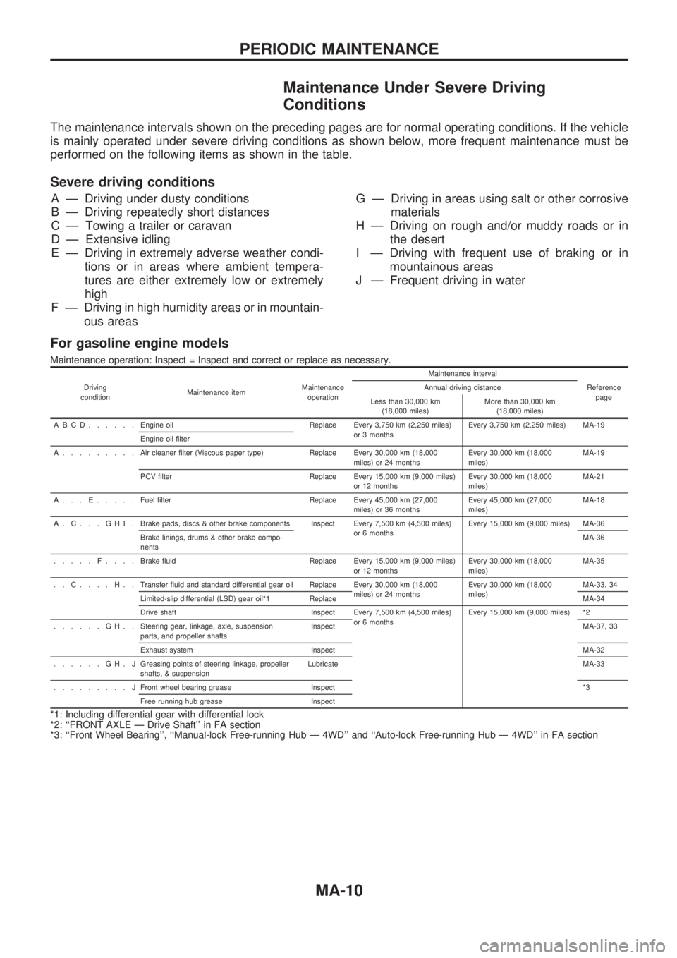
The maintenance intervals shown on the preceding pages are for normal operating conditions. If the vehicle
is mainly operated under severe driving conditions as shown below, more frequent maintenance must be
performed on the following items as shown in the table.
Severe driving conditions
A Ð Driving under dusty conditions
B Ð Driving repeatedly short distances
C Ð Towing a trailer or caravan
D Ð Extensive idling
E Ð Driving in extremely adverse weather condi-
tions or in areas where ambient tempera-
tures are either extremely low or extremely
high
F Ð Driving in high humidity areas or in mountain-
ous areasG Ð Driving in areas using salt or other corrosive
materials
H Ð Driving on rough and/or muddy roads or in
the desert
I Ð Driving with frequent use of braking or in
mountainous areas
J Ð Frequent driving in water
For gasoline engine models
Maintenance operation: Inspect = Inspect and correct or replace as necessary.
Driving
conditionMaintenance itemMaintenance
operationMaintenance interval
Reference
page Annual driving distance
Less than 30,000 km
(18,000 miles)More than 30,000 km
(18,000 miles)
ABCD......Engine oil Replace Every 3,750 km (2,250 miles)
or 3 monthsEvery 3,750 km (2,250 miles) MA-19
Engine oil filter
A.........Aircleaner filter (Viscous paper type) Replace Every 30,000 km (18,000
miles) or 24 monthsEvery 30,000 km (18,000
miles)MA-19
PCV filter Replace Every 15,000 km (9,000 miles)
or 12 monthsEvery 30,000 km (18,000
miles)MA-21
A...E.....Fuel filter Replace Every 45,000 km (27,000
miles) or 36 monthsEvery 45,000 km (27,000
miles)MA-18
A.C...GHI.Brake pads, discs & other brake components Inspect Every 7,500 km (4,500 miles)
or 6 monthsEvery 15,000 km (9,000 miles) MA-36
Brake linings, drums & other brake compo-
nentsMA-36
.....F....Brake fluid Replace Every 15,000 km (9,000 miles)
or 12 monthsEvery 30,000 km (18,000
miles)MA-35
..C....H..Transfer fluid and standard differential gear oil Replace Every 30,000 km (18,000
miles) or 24 monthsEvery 30,000 km (18,000
miles)MA-33, 34
Limited-slip differential (LSD) gear oil*1 ReplaceMA-34
Drive shaft Inspect Every 7,500 km (4,500 miles)
or 6 monthsEvery 15,000 km (9,000 miles) *2
......GH..Steering gear, linkage, axle, suspension
parts, and propeller shaftsInspectMA-37, 33
Exhaust system InspectMA-32
......GH.JGreasing points of steering linkage, propeller
shafts, & suspensionLubricateMA-33
.........JFront wheel bearing grease Inspect*3
Free running hub grease Inspect
*1: Including differential gear with differential lock
*2: ``FRONT AXLE Ð Drive Shaft'' in FA section
*3: ``Front Wheel Bearing'', ``Manual-lock Free-running Hub Ð 4WD'' and ``Auto-lock Free-running Hub Ð 4WD'' in FA section
PERIODIC MAINTENANCE
MA-10
Page 991 of 1659
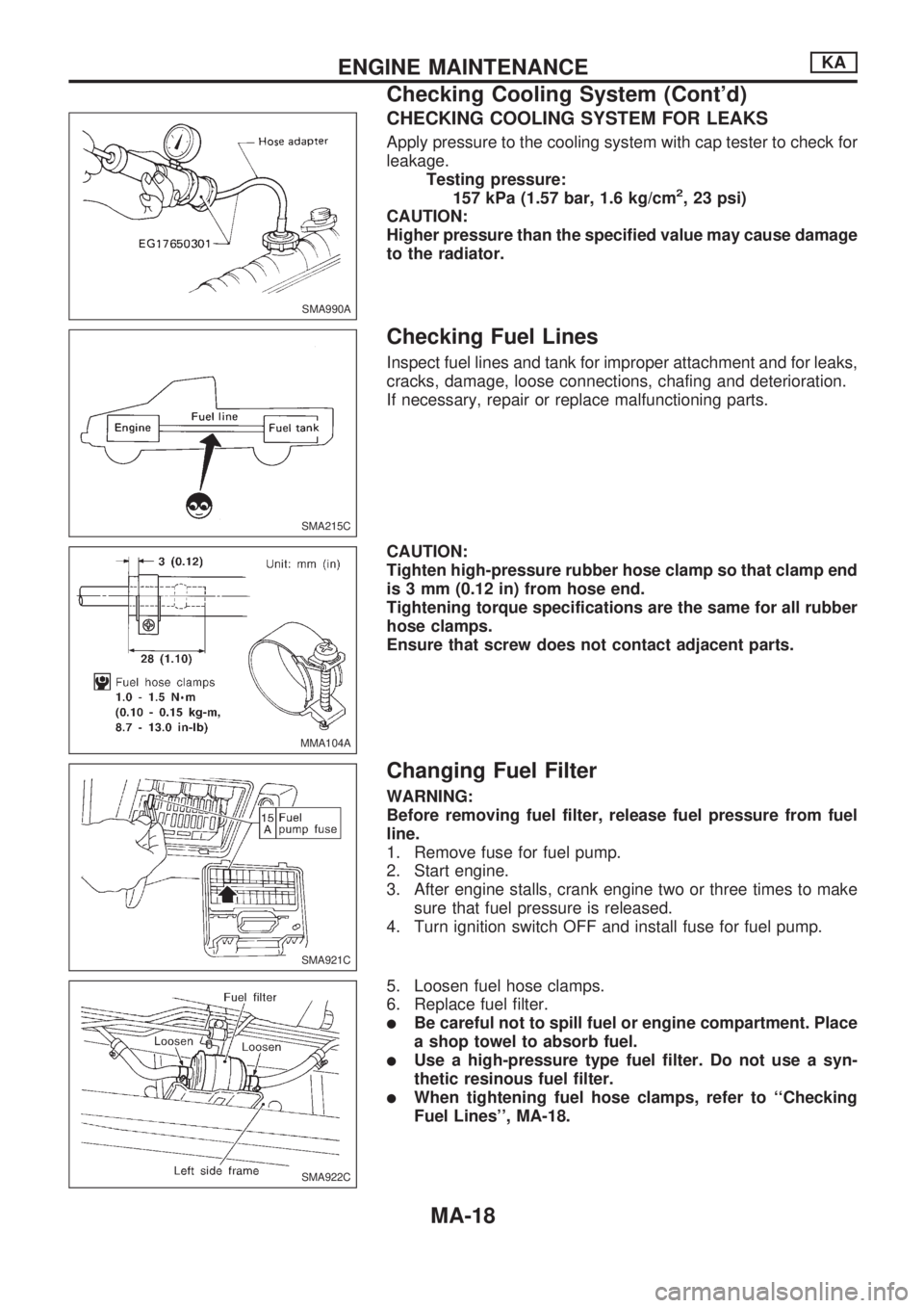
CHECKING COOLING SYSTEM FOR LEAKS
Apply pressure to the cooling system with cap tester to check for
leakage.
Testing pressure:
157 kPa (1.57 bar, 1.6 kg/cm
2, 23 psi)
CAUTION:
Higher pressure than the specified value may cause damage
to the radiator.
Checking Fuel Lines
Inspect fuel lines and tank for improper attachment and for leaks,
cracks, damage, loose connections, chafing and deterioration.
If necessary, repair or replace malfunctioning parts.
CAUTION:
Tighten high-pressure rubber hose clamp so that clamp end
is 3 mm (0.12 in) from hose end.
Tightening torque specifications are the same for all rubber
hose clamps.
Ensure that screw does not contact adjacent parts.
Changing Fuel Filter
WARNING:
Before removing fuel filter, release fuel pressure from fuel
line.
1. Remove fuse for fuel pump.
2. Start engine.
3. After engine stalls, crank engine two or three times to make
sure that fuel pressure is released.
4. Turn ignition switch OFF and install fuse for fuel pump.
5. Loosen fuel hose clamps.
6. Replace fuel filter.
lBe careful not to spill fuel or engine compartment. Place
a shop towel to absorb fuel.
lUse a high-pressure type fuel filter. Do not use a syn-
thetic resinous fuel filter.
lWhen tightening fuel hose clamps, refer to ``Checking
Fuel Lines'', MA-18.
SMA990A
SMA215C
MMA104A
SMA921C
SMA922C
ENGINE MAINTENANCEKA
Checking Cooling System (Cont'd)
MA-18
Page 1014 of 1659
Checking Body Corrosion
Visually check the body sheet metal panel for corrosion, paint damage (scratches, chipping, rubbing, etc.)
or damage to the anti-corrosion materials. In particular, check the following locations.
Hemmed portion
Hood front end, door lower end, trunk lid rear end, etc.
Panel joint
Side sill of rear fender and center pillar, rear wheel housing of rear fender, around strut tower in engine
compartment, etc.
Panel edge
Trunk lid opening, sunroof opening, fender wheelarch flange, fuel filler lid flange, around holes in panel, etc.
Parts contact
Waist molding, windshield molding, bumper, etc.
Protectors
Damage or condition of mudguard, fender protector, chipping protector, etc.
Anti-corrosion materials
Damage or separation of anti-corrosion materials under the body.
Drain holes
Condition of drain holes at door and side sill.
When repairing corroded areas, refer to the Corrosion Repair Manual.
CHASSIS AND BODY MAINTENANCE
MA-41
Page 1091 of 1659
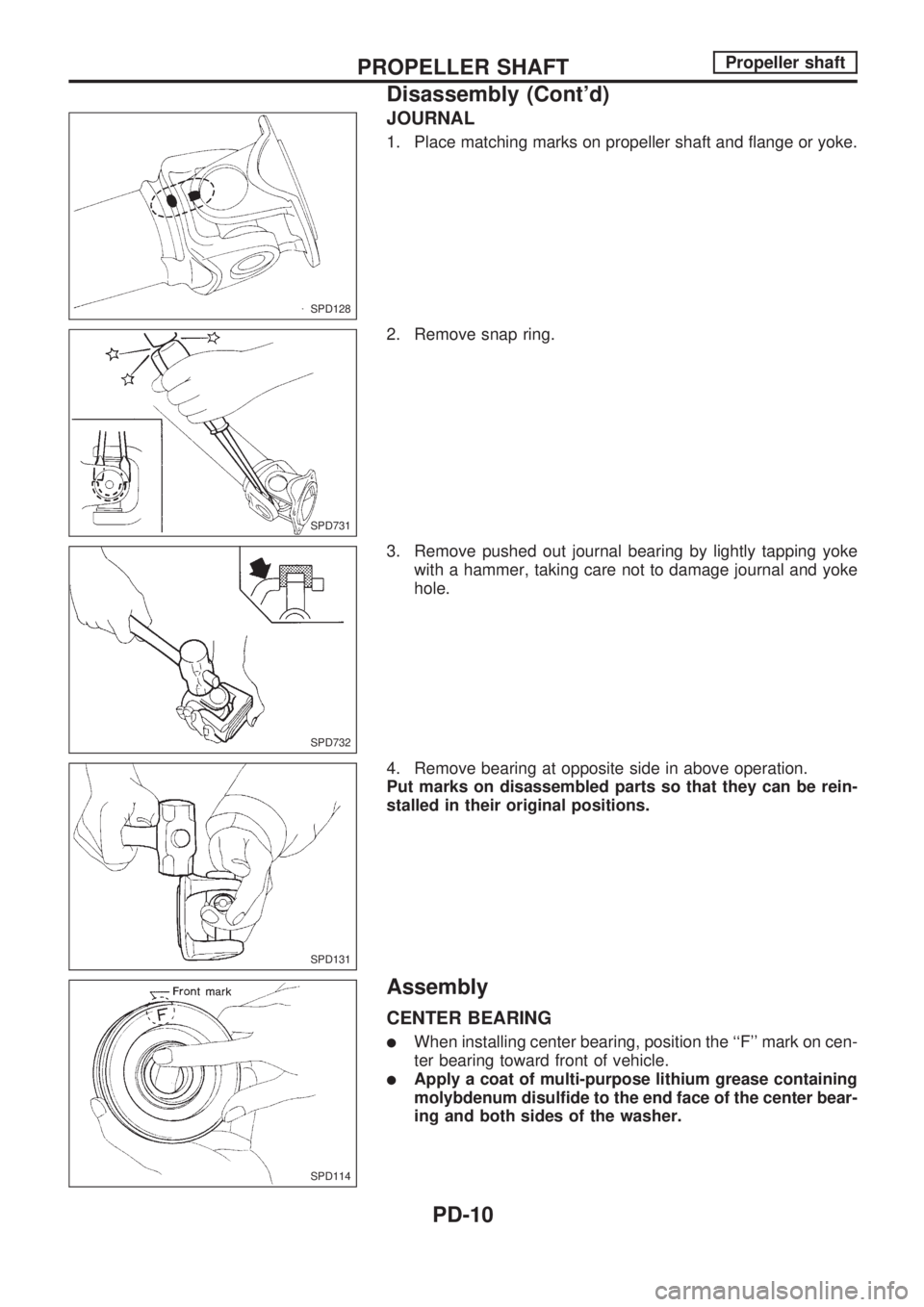
JOURNAL
1. Place matching marks on propeller shaft and flange or yoke.
2. Remove snap ring.
3. Remove pushed out journal bearing by lightly tapping yoke
with a hammer, taking care not to damage journal and yoke
hole.
4. Remove bearing at opposite side in above operation.
Put marks on disassembled parts so that they can be rein-
stalled in their original positions.
Assembly
CENTER BEARING
lWhen installing center bearing, position the ``F'' mark on cen-
ter bearing toward front of vehicle.
lApply a coat of multi-purpose lithium grease containing
molybdenum disulfide to the end face of the center bear-
ing and both sides of the washer.
SPD128
SPD731
SPD732
SPD131
SPD114
PROPELLER SHAFTPropeller shaft
Disassembly (Cont'd)
PD-10
Page 1169 of 1659
Precautions for SRS ``AIR BAG'' Service
lDo not use a circuit tester to check SRS circuits unless instructed to in this Service Manual.
lBefore servicing the SRS, turn ignition switch ``OFF'', disconnect both battery cables and wait for at least
3 minutes.
For approximately 3 minutes after the cables are removed, it is still possible for the air bag to deploy.
Therefore, do not work on any SRS connectors or wires until at least 3 minutes have passed.
lFor 2WD models, do not separate diagnosis sensor unit from steering wheel.
lFor 4WD models, diagnosis sensor unit must always be installed with their arrow marks ``S'' pointing
towards the front of the vehicle for proper operation. Also check diagnosis sensor unit for cracks,
deformities or rust before installation and replace as required.
lThe spiral cable must be aligned with the neutral position since its rotations are limited. Do not attempt
to turn steering wheel or column after removal of steering gear.
lHandle air bag module carefully. Always place it with the pad side facing upward.
lConduct self-diagnosis to check entire SRS for proper function after replacing any components.
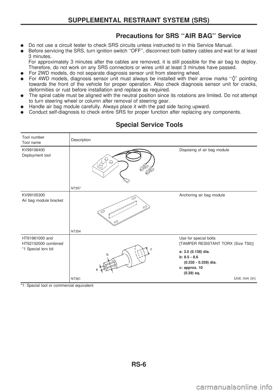
Special Service Tools
Tool number
Tool nameDescription
KV99106400
Deployment tool
NT357
Disposing of air bag module
KV99105300
Air bag module bracket
NT354
Anchoring air bag module
HT61961000 and
HT62152000 combined
*1 Special torx bit
NT361
Use for special bolts
[TAMPER RESISTANT TORX (Size T50)]
a: 3.5 (0.138) dia.
b: 8.5 - 8.6
(0.335 - 0.339) dia.
c: approx. 10
(0.39) sq.
Unit: mm (in)
*1: Special tool or commercial equivalent
SUPPLEMENTAL RESTRAINT SYSTEM (SRS)
RS-6