Page 727 of 1659
REPLACING CAMSHAFT BUSHING
1. Using Tool, remove camshaft bushings from the engine.
Some bushings must be broken in order to remove.
2. Using Tool, install camshaft bushings as follows:
(1) Install camshaft bushings in the order of ``rear'', ``4th'', ``3rd'',
``2nd'' and ``front''. All bushings must be installed from the
front.
(2) Face the cutout upward and toward the front of the engine
during installation.
(3) Rear camshaft bushing
lAlign the cutout of rear bushing with knock pin of replacer bar
before installation.
lInsert rear bushing with replacer bar into the engine.
Install guide plate with bolt holes (on the ``TD'' mark side)
facing upper side of cylinder block. Tighten bolts.
SEM106C
SEM993B
SEM686B
SEM995B
SEM110C
ENGINE OVERHAULTD
Inspection and Replacement (Cont'd)
EM-82
Page 787 of 1659
DISASSEMBLY
Final drive side (TS82F)
1. Remove plug seal from slide joint housing by lightly tapping
around slide joint housing.
2. Remove boot bands.
3. Move boot and slide joint housing toward wheel side, and put
matching marks.
4. Remove snap ring.
5. Detach spider assembly with press.
6. Draw out boot.
Cover drive shaft serration with tape to prevent damaging
the boot.
SFA880
SFA963
SFA964
SFA392
SFA799
FRONT AXLE
Drive Shaft Ð 4WD Ð (Cont'd)
FA-22
Page 804 of 1659

GENERAL INFORMATION
SECTION
GI
CONTENTS
PRECAUTIONS......................................................... 1
Precautions for Supplemental Restraint
System (SRS) ``AIR BAG'' (4WD models)............. 1
Precautions for Supplemental Restraint
System (SRS) ``AIR BAG'' (2WD models)............. 1
Precautions for NATS ............................................ 2
General Precautions .............................................. 2
Precautions for Multiport Fuel Injection System
or ECCS Engine .................................................... 4
Precautions for Three Way Catalyst
(If so equipped) ...................................................... 4
Precautions for Engine Oils ................................... 4
Precautions for Fuel............................................... 5
Precautions for Air Conditioning ............................ 6
HOW TO USE THIS MANUAL.................................. 7
HOW TO READ WIRING DIAGRAMS...................... 9
Sample/Wiring Diagram - EXAMPL - .................... 9
Description ........................................................... 11
HOW TO CHECK TERMINAL................................. 18
How to Probe Connectors ................................... 18
How to Check Enlarged Contact Spring of
Terminal ............................................................... 19
Waterproof Connector Inspection ........................ 20
Terminal Lock Inspection ..................................... 20
HOW TO PERFORM EFFICIENT DIAGNOSIS
FOR AN ELECTRICAL INCIDENT......................... 21
Work Flow ............................................................ 21HOW TO PERFORM EFFICIENT DIAGNOSIS...... 22
Incident Simulation Tests..................................... 22
Circuit Inspection ................................................. 25
HOW TO FOLLOW FLOW CHART IN
TROUBLE DIAGNOSES......................................... 31
How to Follow This Flow Chart ........................... 32
CONSULT CHECKING SYSTEM............................ 34
Function and System Application ........................ 34
Lithium Battery Replacement............................... 34
Checking Equipment ............................................ 35
Loading Procedure............................................... 36
CONSULT Data Link Connector (DLC) Circuit ... 36
IDENTIFICATION INFORMATION.......................... 37
Model Variation .................................................... 37
Identification Number ........................................... 40
Dimensions .......................................................... 44
Wheels and Tires ................................................. 46
LIFTING POINTS AND TOW TRUCK TOWING..... 47
Pantograph Jack .................................................. 47
Screw Jack........................................................... 48
Garage Jack and Safety Stand ........................... 49
2-pole Lift ............................................................. 50
Tow Truck Towing ............................................... 51
Towing Point ........................................................ 53
TIGHTENING TORQUE OF STANDARD BOLTS.. 54
SAE J1930 TERMINOLOGY LIST.......................... 55
SAE J1930 Terminology List ............................... 55
GI
Page 851 of 1659
WARNING:
lNever get under the vehicle while it is supported only by the jack. Always use safety stands to
support the frame when you have to get under the vehicle.
lPlace wheel chocks at both front and back of the wheels on the ground.
Pantograph Jack
SGI054A
LIFTING POINTS AND TOW TRUCK TOWING
GI-47
Page 852 of 1659
Screw Jack
SGI055A
LIFTING POINTS AND TOW TRUCK TOWING
GI-48
Page 853 of 1659
Garage Jack and Safety Stand
CAUTION:
Place a wooden or rubber block between safety stand and vehicle body when the supporting body
is flat.
SGI971
LIFTING POINTS AND TOW TRUCK TOWING
GI-49
Page 854 of 1659
2-pole Lift
WARNING:
When lifting the vehicle, open the lift arms as wide as possible and ensure that the front and rear of
the vehicle are well balanced.
When setting the lift arm, do not allow the arm to contact the brake tubes, brake cable or fuel lines.
SGI972
LIFTING POINTS AND TOW TRUCK TOWING
GI-50
Page 855 of 1659

Tow Truck Towing
CAUTION:
lAll applicable local laws regarding the towing operation must be obeyed.
lIt is necessary to use proper towing equipment to avoid possible damage to the vehicle during
towing operation.
lAttach safety chains for all towing.
lWhen towing, make sure that the transmission, steering system and powertrain are in good order.
If any unit is damaged, a dolly must be used.
lWhen towing with the front wheels on the ground:
Turn the ignition key to the ``OFF'' position and secure the steering wheel in a straight ahead
position with a rope or similar device. Never place the ignition key in the ``LOCK'' position. This
will result in damage to the steering lock mechanism.
lWhen towing with the rear wheels on the ground, release the parking brake and move the gear-
shift lever to neutral position (``N'' position).
lNever tow vehicle from the rear (i.e., backward) with four wheels on the ground as this may cause
serious and expensive damage to the transmission.
lFor 4-wheel drive model:
Set the free-running hubs to the free position. Move the transfer case shift lever into the ``2H''
position and the transmission shift lever into the neutral (``N'') position.
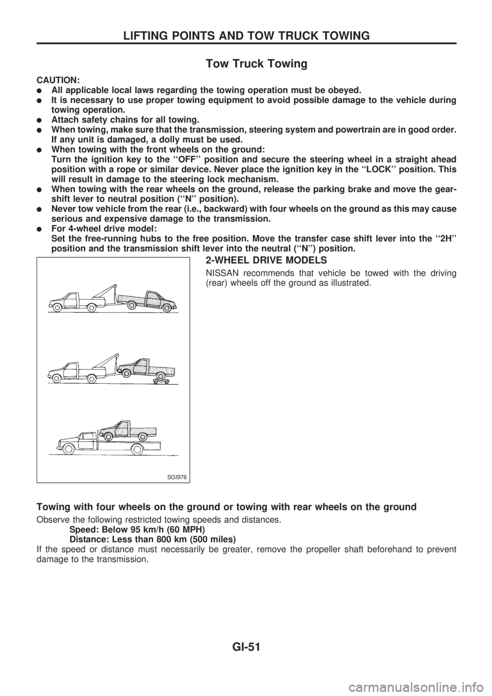
2-WHEEL DRIVE MODELS
NISSAN recommends that vehicle be towed with the driving
(rear) wheels off the ground as illustrated.
Towing with four wheels on the ground or towing with rear wheels on the ground
Observe the following restricted towing speeds and distances.
Speed: Below 95 km/h (60 MPH)
Distance: Less than 800 km (500 miles)
If the speed or distance must necessarily be greater, remove the propeller shaft beforehand to prevent
damage to the transmission.
SGI976
LIFTING POINTS AND TOW TRUCK TOWING
GI-51