Page 1586 of 1659
Assembly
1. Install valve component parts.
lAlways use new valve oil seal. Refer to OIL SEAL
REPLACEMENT.
lBefore installing valve oil seal, install inner valve spring
seat.
lInstall outer valve spring (uneven pitch type) with its
narrow pitch side toward cylinder head side.
lAfter installing valve component parts, use plastic ham-
mer to lightly tap valve stem tip to assure a proper fit.
2. Install camshaft, placing knock pin towards front of engine
and in the top position.
lApply engine oil to camshaft when mounting onto cylin-
der head.
3. Install camshaft brackets.
lFront mark is punched on the camshaft bracket.
Location (from front side)Identification
Mark Punched
No. 1 51 Ð
No. 2 52 2
No. 3 53 Ð
No. 4 52 4
No. 5 55 Ð
4. Install rocker shaft with rocker arms.
lInstall retainer with cutout facing direction shown in figure at
left.
SEM638B
SEM236C
SEM606F
SEM399E
SEM274C
CYLINDER HEADKA
EM-33
Page 1600 of 1659

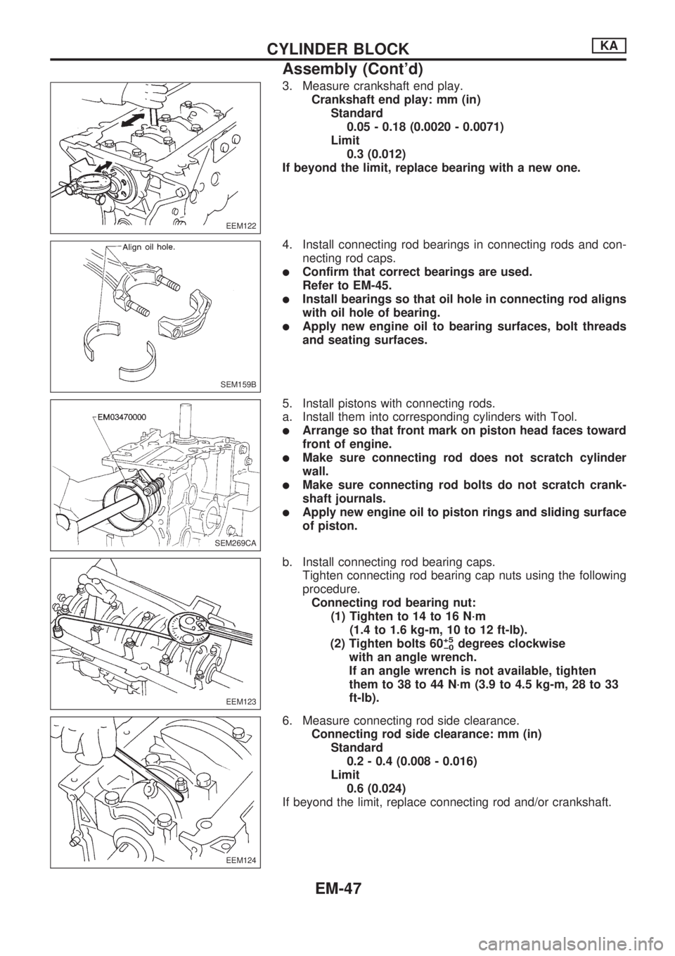
3. Measure crankshaft end play.
Crankshaft end play: mm (in)
Standard
0.05 - 0.18 (0.0020 - 0.0071)
Limit
0.3 (0.012)
If beyond the limit, replace bearing with a new one.
4. Install connecting rod bearings in connecting rods and con-
necting rod caps.
lConfirm that correct bearings are used.
Refer to EM-45.
lInstall bearings so that oil hole in connecting rod aligns
with oil hole of bearing.
lApply new engine oil to bearing surfaces, bolt threads
and seating surfaces.
5. Install pistons with connecting rods.
a. Install them into corresponding cylinders with Tool.
lArrange so that front mark on piston head faces toward
front of engine.
lMake sure connecting rod does not scratch cylinder
wall.
lMake sure connecting rod bolts do not scratch crank-
shaft journals.
lApply new engine oil to piston rings and sliding surface
of piston.
b. Install connecting rod bearing caps.
Tighten connecting rod bearing cap nuts using the following
procedure.
Connecting rod bearing nut:
(1) Tighten to 14 to 16 N´m
(1.4 to 1.6 kg-m, 10 to 12 ft-lb).
(2) Tighten bolts 60
+5
þ0degrees clockwise
with an angle wrench.
If an angle wrench is not available, tighten
them to 38 to 44 N´m (3.9 to 4.5 kg-m, 28 to 33
ft-lb).
6. Measure connecting rod side clearance.
Connecting rod side clearance: mm (in)
Standard
0.2 - 0.4 (0.008 - 0.016)
Limit
0.6 (0.024)
If beyond the limit, replace connecting rod and/or crankshaft.
EEM122
SEM159B
SEM269CA
EEM123
EEM124
CYLINDER BLOCKKA
Assembly (Cont'd)
EM-47
Page 1615 of 1659
Assembly
1. Assemble rocker shaft component parts.
lFace punch mark toward the front of the engine.
Identification of rocker arms
Identification mark
(At area
Vaon rocker arm)For use with
Two ridges Intake
No ridge Exhaust
2. Install valve component parts.
Identification of valves
Identification mark
(on intake and exhaust valve)
Engine
Intake valve Exhaust valve
2 B TD25
lAlways use new valve oil seal. (Refer to EM-68.)
lInstall valve spring (uneven pitch type) with its narrow
pitch side toward cylinder head side.
DEM034
SEM066C
MEM180A
SEM615F
SEM638B
CYLINDER HEADTD
EM-62
Page 1635 of 1659
REPLACING CAMSHAFT BUSHING
1. Using Tool, remove camshaft bushings from the engine.
Some bushings must be broken in order to remove.
2. Using Tool, install camshaft bushings as follows:
(1) Install camshaft bushings in the order of ``rear'', ``4th'', ``3rd'',
``2nd'' and ``front''. All bushings must be installed from the
front.
(2) Face the cutout upward and toward the front of the engine
during installation.
(3) Rear camshaft bushing
lAlign the cutout of rear bushing with knock pin of replacer bar
before installation.
lInsert rear bushing with replacer bar into the engine.
Install guide plate with bolt holes (on the ``TD'' mark side)
facing upper side of cylinder block. Tighten bolts.
SEM106C
SEM993B
SEM686B
SEM995B
SEM110C
ENGINE OVERHAULTD
Inspection and Replacement (Cont'd)
EM-82